6
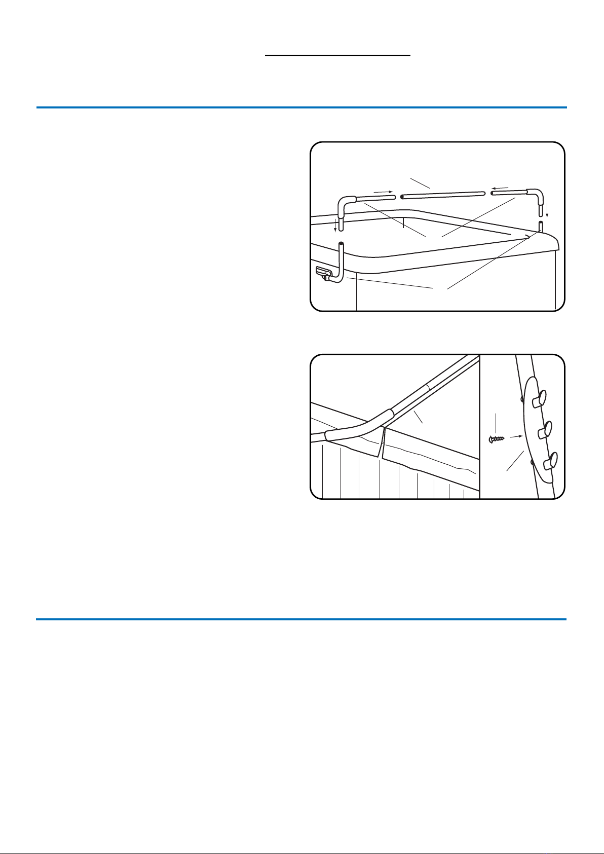
Step #10 - Finishing Up
Snap the Small Black Dome Caps (Q) on the heads of all exposed #10
Mounting Screws. Push the 7/16” plug (R) into the unused hole on
the mounting bracket. Place the Large Black Dome Caps (P) onto the
exposed Hex Cap Bolt head.
If using the TowelMate (I), install onto the side of the Pivot Arm by
replacing the self-tapping screws where required (see ‘Figure 8’).
Removing Cabinetry with a Cover Lifter Installed
Start by making sure the cover is on the spa pool and the cover lifter is in the closed position. Remove the Small Black Dome Caps (Q) on the heads of the
#10 Mounting Screws holding the Mounting Bracket onto the cabinetry. Remove the 12x #10 Mounting Screws from each Mounting Bracket. It might
pay to get a second person to hold one side while it’s being removed to prevent the Mounting Bracket dropping, which could scratch the cabinetry.
When all #10 Mounting Screws have been removed from the Mounting Brackets, gently lift the cover lifter o the spa pool.
If you only require access to the cabinetry on one side, remove the 12x #10 Mounting Screws from the Mounting Bracket, then remove the 3x #10 self
tapping screws holding the Support Arm (A) to the Pivoting Arm (D).
You can now continue to remove the slats and cabinetry to gain access into the Spa. Once you have ready to reinstall the cover lifter, reinstall the cabi-
netry using its pre-existing screw holes. Then secure the Mounting Bracket back in place using the pre-existing screw holes. Snap the Small Black Dome
Caps (Q) on the heads of all exposed #10 Mounting Screws.
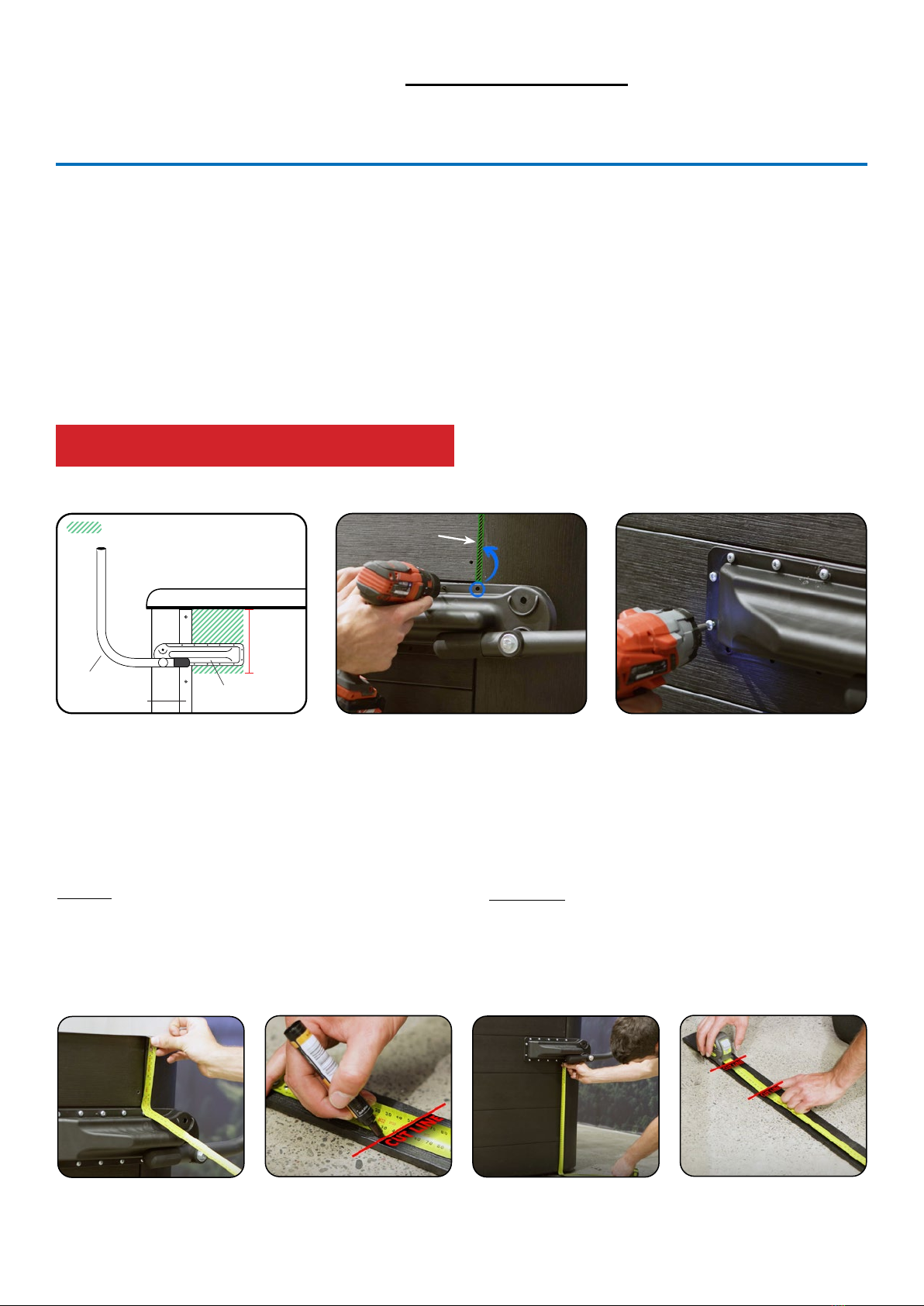
Step #9 - Set the Positioning of Centre
Coupler & Support Arms
Lay the lifter bar down on the spa cover. Adjust the Center Coupler
(C) piece and Support Arms (A) so that the Center Coupler is laying
parallel to the spa cover’s hinge about 1cm away (see ‘Figure 7’).
Using the #10 self tapping screws (N), fasten the support arms to the
pivot arms and the center coupler piece.
Note: Before screwing in screws, be sure to rotate the center coupler
so that the screws are screwed in at a horizontal angle (parallel with
the spa cover). This way when the cover folds over the lifter bar,
the screw heads will not rub on the cover. Consider placing a piece
of cardboard underneath where you are screwing into the center
coupler to catch the metal shavings.
Step #8 - Setup the Support Arms &
Center Coupler
Insert the long end of the Support Arms (A) into the Center Coupler (C)
then slide the short ends of the Support Arms into the Pivot Arms (D)
(see ‘Figure 6’). We will refer to connected Support Arms and Center
Coupler bar as the ‘lifter bar’ for the next step.
Step #7 - Replacing the Slat Pieces
Replace the freshly cut top and bottom slat pieces into their correct
positions either side of the mounting bracket. Simply screw back in
to their pre-existing holes in the cabinet.
Covermate I Plastic
Installation Instructions - Updated as of 08/30/12
Step #1
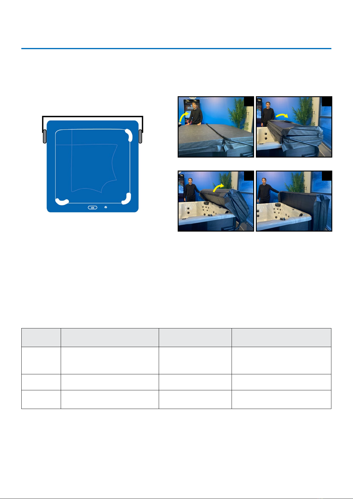
Position the spa cover (in closed position) on the spa, making sure that all four corners
are properly positioned and square on the spa.
CMI-PLAST 120830
Step #2
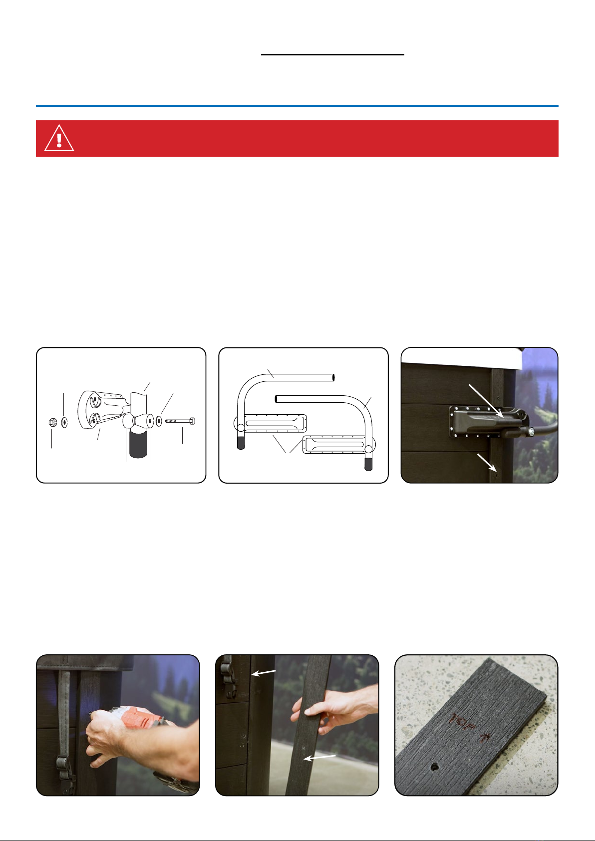
Using the #10 x 1” mounting screws, attach the left and right Mounting Brackets to the
appropriate sides of the spa. Caution: to prevent splitting of wood cabinet, pre-drill
holes with a 1/16” drill bit. Mounting height is optional (see Fig. 1). By positioning the
Brackets 8” down from the top of the spa shell, approx. 9” of clearance behind the spa
will be needed. Mounted at this position approximately 75% of the spa cover will be
standing above the spa surface in the o position. By positioning the Brackets 12”
down from the top of the spa shell, approx. 15” clearance behind the spa will be
needed. Mounted at this position, approximately 50% of the spa cover will be standing
above the spa surface in the o position.
Step #3
Connect the Pivot Arms to the Mounting Brackets (see Fig. 2). After the Pivot Arms are
connected, tilt them back into the upright position.
Step #4
Insert the long end of the Support Arms into the Center Coupler piece. Then slide the
Support Arms into the Pivot Arms (see Fig. 3).
Step #5
Lay the Covermate on the spa cover. Adjust the Center Coupler piece and Support
Arms so that the Center Coupler is laying parallel to the spa cover’s hinge about 1/2”
away (see Fig. 4). Using the #10 self tapping screws, fasten the Support Arms to the
Pivot Arms and the Center Coupler piece. Note: Be sure to rotate the Center Coupler
so that the inserted screws are at a horizontal angle with the heads facing the back
of the spa.
Step #6
Slip the black hand grips to the edge of the spa cover and snap the Small Black Dome
Caps on the heads of all exposed #10 screw heads. Push the 7/16” plug into the
unused bracket (H) hole.
CAUTION!
Do not use the Covermate in high wind condition. Injury from the spa cover being
blown over and impacting the spa user can occur.
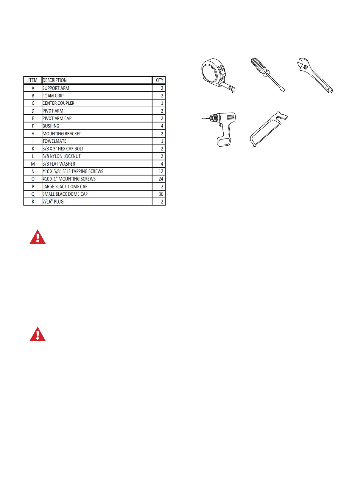
ITEM PART# DESCRIPTION QTY
C 100003 CENTER COUPLER 1
H 100021 MOUNTING BRACKET 2
K 100010 3/8 X 3" HEX CAP BOLT 2
L 100011 3/8 NYLON LOCKNUT 2
M 100012 3/8 FLAT WASHER 4
N 100013 #10 X 5/8" SELF TAPPING SCREWS 12
O 100014 #10 X 1" MOUNTING SCREWS 24
P 100015 LARGE BLACK DOME CAP 2
Q 100016 SMALL BLACK DOME CAP 36
Step #7
Attach the provided 3 hook TowelMate on the preferred side of your Covermate by
simply snapping it into place and inserting the middle self tapping screw (see Fig. 5).
Pivot Arm
Support Arm
Center Coupler
Cover Hinge
Figure 4 Figure 5
Figure 3
A
C
D
I
TowelMate
Figure 1
Figure 2
D
K
H
Figure 1
Mounting Bracket
H
M
M
L
N
Self-
Tapping
Screw
Mounting Bracket
Pivot Arm
Washer Washer
Hex Cap Bolt
Locknut
INSTRUCTIONS FOR ALPINE SPAS MODELS - 3/3
Covermate I Plastic
Installation Instructions - Updated as of 08/30/12
Step #1
Position the spa cover (in closed position) on the spa, making sure that all four corners
are properly positioned and square on the spa.
CMI-PLAST 120830
Step #2
Using the #10 x 1” mounting screws, attach the left and right Mounting Brackets to the
appropriate sides of the spa. Caution: to prevent splitting of wood cabinet, pre-drill
holes with a 1/16” drill bit. Mounting height is optional (see Fig. 1). By positioning the
Brackets 8” down from the top of the spa shell, approx. 9” of clearance behind the spa
will be needed. Mounted at this position approximately 75% of the spa cover will be
standing above the spa surface in the o position. By positioning the Brackets 12”
down from the top of the spa shell, approx. 15” clearance behind the spa will be
needed. Mounted at this position, approximately 50% of the spa cover will be standing
above the spa surface in the o position.
Step #3
Connect the Pivot Arms to the Mounting Brackets (see Fig. 2). After the Pivot Arms are
connected, tilt them back into the upright position.
Step #4
Insert the long end of the Support Arms into the Center Coupler piece. Then slide the
Support Arms into the Pivot Arms (see Fig. 3).
Step #5
Lay the Covermate on the spa cover. Adjust the Center Coupler piece and Support
Arms so that the Center Coupler is laying parallel to the spa cover’s hinge about 1/2”
away (see Fig. 4). Using the #10 self tapping screws, fasten the Support Arms to the
Pivot Arms and the Center Coupler piece. Note: Be sure to rotate the Center Coupler
so that the inserted screws are at a horizontal angle with the heads facing the back
of the spa.
Step #6
Slip the black hand grips to the edge of the spa cover and snap the Small Black Dome
Caps on the heads of all exposed #10 screw heads. Push the 7/16” plug into the
unused bracket (H) hole.
CAUTION!
Do not use the Covermate in high wind condition. Injury from the spa cover being
blown over and impacting the spa user can occur.
ITEM PART# DESCRIPTION QTY
C 100003 CENTER COUPLER 1
H 100021 MOUNTING BRACKET 2
K 100010 3/8 X 3" HEX CAP BOLT 2
L 100011 3/8 NYLON LOCKNUT 2
M 100012 3/8 FLAT WASHER 4
N 100013 #10 X 5/8" SELF TAPPING SCREWS 12
O 100014 #10 X 1" MOUNTING SCREWS 24
P 100015 LARGE BLACK DOME CAP 2
Q 100016 SMALL BLACK DOME CAP 36
Step #7
Attach the provided 3 hook TowelMate on the preferred side of your Covermate by
simply snapping it into place and inserting the middle self tapping screw (see Fig. 5).
Pivot Arm
Support Arm
Center Coupler
Cover Hinge
Figure 4 Figure 5
Figure 3
A
C
D
I
TowelMate
Figure 1
Figure 2
D
K
H
Figure 1
Mounting Bracket
H
M
M
L
N
Self-
Tapping
Screw
Mounting Bracket
Pivot Arm
Washer Washer
Hex Cap Bolt
Locknut
Figure 6
Figure 7 Figure 8
Fuji, Nordic, Belmont, Oregon, Nepal, Tibet, Vermont, Aspen, Nevada, Blackburn, Sierra, Matterhorn, Vancouver, Munro, Nevada, Entertainer