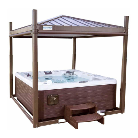
page-8EVOLUTION COVER
IMPORTANT INFORMATION
DANGER, WARNING, CAUTION and NOTE are
used throughout this manual to emphasize
important points when necessary:
DANGER
Directs the user's attention to unsafe practices
which could result in serious personal injury or
death.
WARNING
Directs the user’s attention to unsafe practices
which could result in serious personal injury or
severe damage to the cover.
CAUTION
Directs the user’s attention to unsafe practices
where personal injury is not likely but damage to
cover components could occur.
NOTE
Indicates supplementary information essential to
the proper operation of the cover, proper
installation or proper maintenance.
The lifespan of your new cover depends on the kind
of attention it receives. Pay close attention to the
DANGER, WARNING, CAUTION, and NOTE.
Read the various notices and instructions attached
to the equipment.
Keep this manual in a safe location.
NOTE
Illustrations in this manual are used for reference
only and may differ from the actual cover;
however, key components addressed in the
manual are represented as accurately as
possible.
Before reproducing or copying this manual, in
whole or in part, written consent must be obtained
from Covana. Covana reserves the right to make
changes without notice and without incurring any
obligation.
SAFETY
The cover was designed, tested and certified to be
installed over a residential spa under important
installation instructions issued by Covana. Any
other type of usage will void the warranty and
product certification.
The cover was not designed to support any
additional load or people walking or standing on its
lid. Failure to observe this instruction will void the
cover warranty and nullify its certification.
The power safety cover meets ASTM F1346- 91
requirements.
DRUGS AND ALCOHOL
DANGER
The use of drugs or alcohol while operating the
cover is strictly prohibited. The impairment of
judgment, vision or hearing might affect the safety
of other people or result in death.
IMPORTANT
SAFETY
INSTRUCTIONS
WARNING
KEEP THESE INSTRUCTIONS IN A SAFE
LOCATION.
REVIEW THESE INSTRUCTIONS REGULARLY.
NOTE
READ AND FOLLOW ALL INSTRUCTIONS.
WARNING
CALIFORNIA PROPOSITION 65
This product contains chemicals known to the
State of California to cause cancer and birth
defects or other reproductive harm.
252808 OWNER'S MANUAL REVISION 0


