Takara Belmont YUME ESPOIR User manual

YUME ESPOIR Installation Instructions
YUME ESPOIR
Basin body
[For Back wash] Type
Seat body
[Fixed Legrest] Type
[Movable Legrest] Type
Seat
[Fixed Legrest] Type
[Movable Legrest] Type
Base plate
(Image is of “Movable legrest” type)
(Image is of “Fixed legrest” type)
Contents
Before installation 2
Usage conditions 5
YUME ESPOIR packing 6
Carrying the main body 8
Installation of main body 9
1 Install the basin 9
2 Attach piping 11
3 Checks after installation of pipes 12
4 Install the seat 13
5 Remove transportation bolt 14
6 Wiring 15
7 Attach base cover 16
8 Check operation (1)
(after assembling the seat) 17
9 Attach backrest and seat 17
10 Check operation (2)
(after attaching the backrest and seat)
18
After installation 19
Attach neck cushion 19
Attachment of the hair trap and the drain cap
19
Main body attachment diagram 20
To the installer
• The instructions should be thoroughly read
and understood before installation to ensure
that YUME ESPOIR is installed correctly.
• After installation, give these instructions to
the customer.
To the customers
• Customers must ask professional to install
YUME ESPOIR.
• Customers must not install YUME ESPOIR
by themselves.
• Customers must store these instructions in
a safe place so as not to lose them.
* The actual shape of YUME ESPOIR and the
images and dimensions listed in these
instructions may be modified and are
subject to change without notice.
Precaution
The precautions listed here are to ensure that YUME ESPOIR can be installed safely, and to prevent any danger or risk to the person installing
YUME ESPOIR or those around them. All of these precautions are important for safety. Takara Belmont is not responsible for any damage or risk
to the person installing YUME ESPOIR or those around them due to accidents if YUME ESPOIR is installed without adhering to the precautions.
If YUME ESPOIR is installed after ignoring this symbol,
"there is the risk of light or moderate injury or physical damage".
Note : Plumbing should be performed by a qualified technician and should meet all national and local plumbing codes and ordinances.
It is the responsibility of purchaser and/or plumber to conform to national and local codes and ordinances.
Takara Belmont does not take any responsibility or liability for plumbing and installation.
1Version 6 February 2020

2
Before installation
650
560
650
210
520
300
373
80
90
Water supply
position
Drain
position
Hot water
supply position
Overall layout diagram
Basin body: Back wash type
Seat body: Fixed legrest type
Top view
*1 The dimensions listed above may vary slightly from model to model.
*2 Ensure that there is ample space surrounding the seat for extremely tall customers or if the surrounding area is used as a
passageway.
Lowest position
Highest position
Wall Wall
295
220 90
70°
5°
15°
15
8°
Drain position
Water supply,
hot water supply position
65 73
1585
690 (Height of seat)
930
850
480 (Height of seat)
800 (Height of neck cushion) (*1)
435 (*2) or more
2950 (*2) or more
1885 630 or more
2020(*2)or more 930
WallWall
Side view
435 or more

3
930
70°
5°
300
373
80
90
Drain
position
Water supply
position
210
520
650
650
560
Hot water
supply position
450 or more
Overall layout diagram
Basin body: Back wash type
Seat body: Movable legrest type
Top view
*1 The dimensions listed above may vary slightly from model to model.
*2 Ensure that there is ample space surrounding the seat for extremely tall customers or if the surrounding area is used as a
passageway.
930
850
800 (Height of neck cushion) (*1)
1970 (*2) or more
1520
WallWall
690 (Height of seat)
480 (Height of seat)
Wall
73
Lowest position
Highest position
2900 (*2) or more
1820
450 (*2) or more 630 or more
15
45°
8°
295
Drain position
Water supply,
hot water supply position
220 90
Wall 30
10°
Side view

4
Wooden floor
Mortar floor Mortar thickness of 50 mm or more
Special floor (stone finish)
A foundation with levels of strength listed above around the installation areas is required.
Plywood thickness of 30 mm or more (two 15 mm sheets joined together)
Power
To turn the power on, install the C-4 plug.
When the plug is changed due to a reason related to the customer, install a power plug that is suitable for the product.
Connecting to ground
To prevent accidents from occurring in the unlikely event of electrocution, and to improve noise resistance within control circuits,
always install the ground designed for this product.
Do not connect the ground cable to any of the following:
Water pipes: any PVC pipes within the plumbing system will prevent a proper ground connection.
Gas pipes: there is a risk of an explosion or fire.
Telephone cables, lightning rods: there is a risk of a large current if there is a lightning strike.
Floor surface
Ensure that the material or finishing of the floor surface is waterproof or has a waterproof coating applied.
Always ensure that the floor surface is horizontally level.
Ensure that the floor surface is smooth and free from bumps around the attachment areas.
If the floor surface is tiled, cracks may occur when fastening the bolts during installation of the YUME ESPOIR main body. If this
looks likely to happen, use the main body attachment diagram and template as a reference and change the material of the
attachment area that is in contact with the floor to another such as plywood or mortar.
Take care during installation as the entire base surface of the seat body is not in contact with the floor.
The following levels of strength are required for the floor surface.
Preventing water leakage
If this product is to be installed upstairs, ensure that the installation area has been coated with waterproof materials (waterproof
finish, installation of a stainless steel pan or a water leakage sensor).
Fill the space between the installation area and pipe with caulking materials.
Precaution
Handling power plugs
Check the power plugs are free from dust, and insert the plug all the way to the base so that there is no rattle.
Dusty power plugs or improper connections can cause electrocution or fires.
Handling power cables
Do not subject power cables to excessive forces, modify, twist or bend them.
Power cables can become severed if they are placed under heavy objects or become trapped within tight areas, and can cause
electrocution or fires.
Handling power outlets
Use power outlets for one appliance only, and always connect the ground terminal.
The use of multi-outlet extension cords can generate heat where the power outlet is divided, and can cause fires.
Handling circuit breakers and fuses
Always install a circuit breaker and fuse with the power outlet. Check that the white cable is neutral, and that the circuit breaker and fuse
are connected properly to the neutral side of the power outlet. Installing circuit breakers off users incorrectly can cause electrocution.
Remove the power plug during inspections
Remove the power plug before conducting inspections or adjusting settings within the main body of YUME ESPOIR.
Coming into contact with electrical part while the power is connected may cause electrocution.
[Rated current]
230V Specifications
[Rated frequency]
50/60Hz
[Rated electricity consumption]
1.9/1.6A

5
Usage conditions
Installation of pipes
The following are important points to adhere to during the installation of pipes.
Read through the details carefully and ensure that the pipes are installed correctly.
When installing this product, ensure that installation of pipes adheres to the instructions outlined in "Precautions during
installation of pipes". Installing pipes without reading through the precautions will mean water may not mix properly, and a set
temperature will not be achieved.
This product is designed for indoor installation. Always install this product indoors.
Precautions during installation of pipes
Do not use pipes made of materials that may introduce rust for the water supply pipe.
In general, the same diameter and same pressure is recommended for hot water pipes and water supply pipes.
Always use a reamer to deburr the ends of cut pipes.
Avoid using inverted U-shaped pipes (siphon) as these can cause air to become trapped.
Always connect hot water pipes and water supply pipes after removing all contaminants such as dirt, sand and oil as these can
cause problems.
After connecting the pipes and testing water flow, clean the filter and shower head.
Do not connect the hot water pipes and water supply pipes in reverse.
Connecting pipes in reverse will mean the temperature of water cannot be controlled properly by the water taps, which can
cause problems including burns.
Ensure that the hot water pipes from water boilers are only run over a short distance so as to minimize resistance.
Longer pipes can cause fluctuations in temperature and poor hot water delivery.
Always wrap pipes with lagging material after installation is complete.
Water boiler pipes
In general, the same diameter and same pressure is recommended for main hot water pipes and main water supply pipes.
Equipment comes with hair catchers installed.
Hot water supply and water supply conditions
Water used
Hot water supply,
water supply pressure
Hot water temperature
into the product
Water boiler
Public water supply (do not use non-drinkable well water or water that contains rust or sand.)
If the water hardness is 80 ppm or higher, install a water softener to prevent the buildup of scale
within the basin body. Aeration may be minimal when using shampoo even if drinkable well
water is used, so a water softener should be installed.
Use a pressure set between 0.1 to 0.4 MPa (1 to 4 kgf/cm2). If multiple YUME ESPOIR are used,
ensure that the pressure does not drop below 0.1 MPa (1 kgf/cm2).
Set the water supply pressure ≧hot water supply pressure.
Set the difference between the hot water supply pressure and water supply pressure to within
0.2 MPa (2 kgf/cm2).
Set the hot water temperature to 60˚C or less.
Set the temperature 10˚C or higher than the shower temperature used.
Do not use steam with the hot water supply.

6
YUME ESPOIR packing
<Basin body>
Content of packaging
Accessories <Same for Back wash type and Side wash type>
* The Urea screws are held down the main body
with the maintenance cover.
(Yuria screw M5 × 15)
Precaution
An air mat is attached to the basin, and
protective tape applied to the main body
cover. In order to protect the basin and
main body cover, do not remove these
until immediately before installation of
the pipes.
Drain cap Hair catcher
Basin body floor fixing screw set
Instruction manual, installation manual (this document)
YUME SPATechnical Manual
Head pillow (1 set)
Pipe packing (sponge)
Cushion tape Drain hose clamp Drain hose packing
Skid
Basin
Air mat
Base
Main body cover
Air mat
Protective tape Maintenancecover
Neck cushion
Drain pipe joint

7
<Seat body>
Content of packaging
<Seat>
Content of packaging
<Base plate>
Content of packaging
Base plate UBase plate H
Base plate F
[Fixed legrest type]
[Movable legrest type]
Seat Seat fixing screw set
Backrest Backrest cover
Cover set
· Base cover fixing screw set
· Base cover R
· Base cover L
·
Seat body floor fixing screw set
BP fixing screw set
(*)Legrest
Areas that must not
be used to carry the
main body
Backrest
Supporting column
Skid
Base
Footing
Areas that can be
used to carry the
main body
Backrest
Seat Seat fixing screw set
Backrest Backrest cover
* There is no legrest
for the Fixed legrest type.

8
Carrying the main body
Foot
part
Seat back
Base
Edge
Basin
Air mat
Main body
cover
Protective tape
Protective tape
Precaution
• Never hold the main body cover.
Doing so may cause damage to the main body cover.
• Take care when handling the basin as it is heavy and fragile.
• Do not drag the unit.
The foot part of the basin is made of steel, so dragging it may
damage the floor surface or crack the basin itself.
• The basin may become damaged if scratched by metallic objects
such as watches or belts.
Remove all metallic objects such as watches when carrying the
basin.
• Take extra care to ensure not to damage the covers.
• Do not touch the basin body pipes.
Doing so may cause water leaks.
•The basin is unstable when it is not fixed to the floor.
Precaution
• Never hold the backrest.
Doing so may cause incorrect operation or malfunctions in the seat.
• Do not drag the seat.
The feet of the seat are made of steel, so dragging it may damage
the floor surface, damage the foot part, cause incorrect operation or
malfunctions in the seat or toppling.
Precaution
Always have at least two people to carry the main body and hold the
basin when remove the bold.
Carrying the basin
1 Unpack the wood frame.
2 Remove the maintenance cover from the main body.
Remove the protective tape and the Urea screws from the maintenance
cover.
* Remove the maintenance cover keeping the protective tape taped to
the main body cover.
3 Remove the main body from the wood frame.
Remove the screw attaching the base and skid while holding the basin.
(4 points)
4 When carrying the basin
Do not take off the air mat and the protective tape.
Carry the body by holding the edge of under the basin. Do not hold the
main body cover. Always have two at least people to carry the main
body. (see image on right)
Carrying the seat
1 Unpack the wood frame.
2 Remove the seat from the wood frame.
Remove the screw attaching the foot part and skid while holding the
seat. (4 points)
3 When carrying the seat
Hold the specified points only. (see page 7)
Always have at least two people to carry the seat. (see image on right)
Precaution
Do not lose the Urea screws holding down the maintenance cover.
The Urea screws are used for holding down the maintenance cover
later. (see page 12)

9
Installation of main body
Install the basin
1
*
The basin or seat may not be able to be installed correctly depending on installation procedures of the main body.
Always install the main body using the following procedures.
Main body installation procedure
Precaution
• Always use the template to mark the floor when fixing the basin and the seat.
Also, always final confirm the fixing position of the seat by using the base plate H as a guideline.
• If the seat is to be fixed using anchor bolts, check the distance between the seat and the basin with the actual unit.
3 Checks after installation of pipes
1 Install the basin
4 Install the seat
Install base plate H to the basin
Install base plate H to the seat
Install the seat
5 Remove bolts for transportation
After installation
Check inspection items
10 Check operation (2)
(after attaching the backrest and seat)
Attach neck cushion
2 Attach piping
7 Attach the base cover
After attaching the base cover,
install base plate F to base plate H.
8 Check operation (1)
(after assembling the seat)
9 Attach backrest and seat
6 Wiring
Install base plate U to base plate H
Hot water supply pipe
Water supply pipe Drain pipe
YUME ESPOIR template
Supplied template
Power cable (for installation)
* Only when installing from the water
supply pipe and drain pipe area
Installation
1 Marking the bolt (anchor) fixing position
Use supplied template to check and make preparations for the
dimensions and method for installation of the piping.
* If the power cable (for installation) is to be installed from the water supply
pipe and drain pipe area, mark their position in the same way as below.
(1) Place the supplied template on the floor and set it to the position
of the water supply pipe, hot water supply pipe and drain pipe.
(2) Mark the fixing position of the basin and seat bolts (anchor).
(3) Drill out the fixing position holes for the basin bolts (anchor).
(4) Remove the template from the floor.

10
→
2 Attach pipe packing
(1)
Cut a slit in the pipe packing to suit the position of the pipes to be installed.
(2) Peel away the sheet from the adhesive surface of the pipe
packing and stick to the floor surface.
(3) Cut out a circle around the slit cut in the pipe packing to suit the
pipe surface, and fill in any gaps with caulking materials.
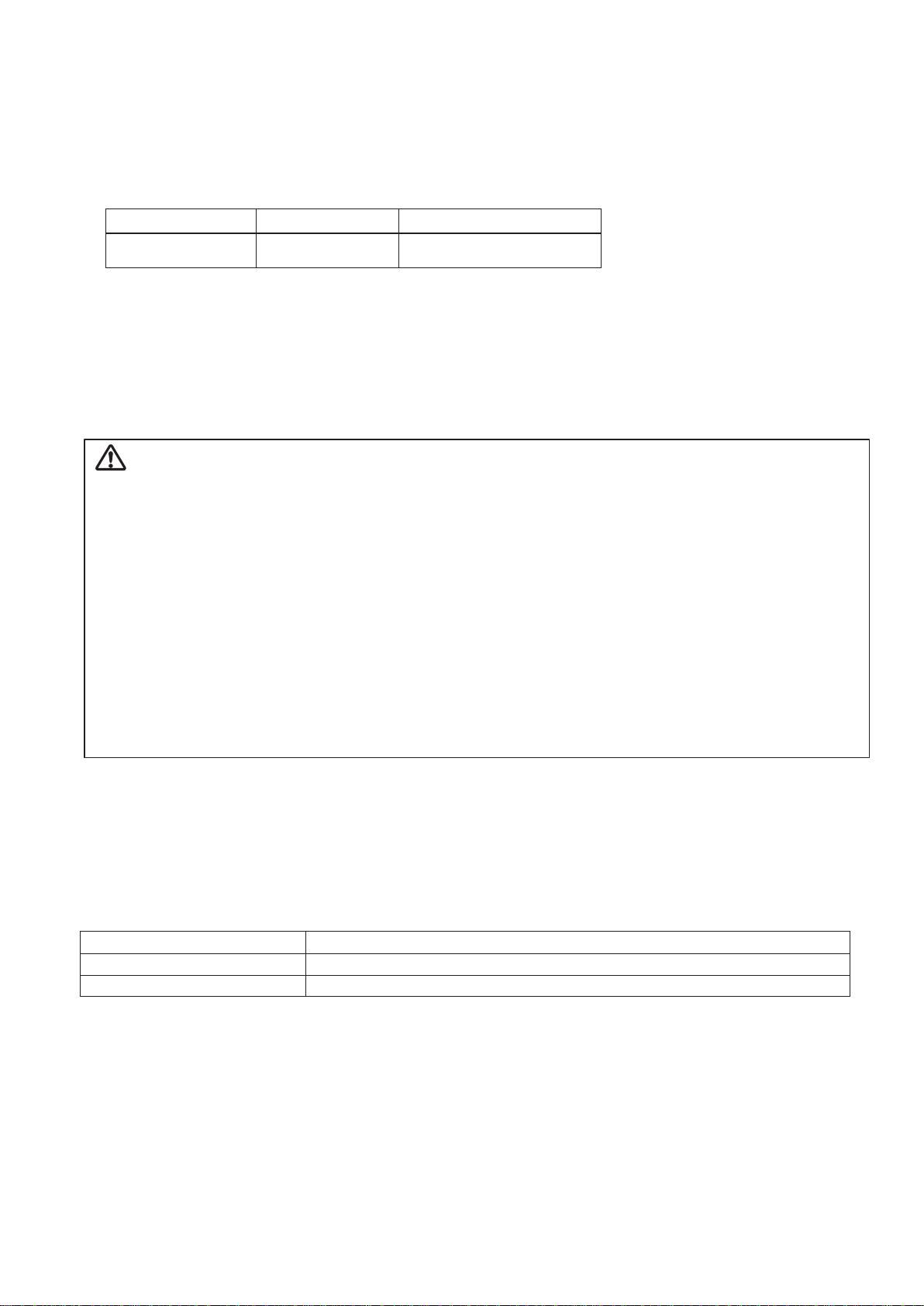
3 Install the basin
(1) Hold the stepped section at the bottom of the basin, align it with
the hole position that was opened previously, and install the basin.
* If the power cable (for installation) is being installed from the water
supply pipe and drain pipe area, pass the cable through the gap in the
center of the base and through to the seat side.
(2) If the pipe packing is trapped under the basin (base), move the
basin away temporarily and cut the pipe packing that is trapped.
(3) Attach the basin with bolts (anchor).
Adjust the basin so that it is not installed at an angle.
Precaution
•
Always attach pipe packing and apply caulking materials to the areas around
the pipes so that there are no gaps, in order to prevent condensation within
YUME ESPOIR or water seeping on the floor in the event of water leaks.
•
If pipe packing is not used, condensation may cause water to pool on the
floor, structural parts may start degrading and malfunctions may occur.
•
If the power cable (for installation) is to be installed from the water supply pipe and
drain pipe area, apply caulking materials to any gaps in the same way as above.
Precaution
Do not pull the basin when attempting to move it. Doing so may
damage the floor.
Precaution
Ensure that the power cable (for installation) is not trapped by the
base. Doing so may cause fires, electrocution or angled basin.
Precaution
The basin may be installed at an angle, or may even topple over if the
basin (base) is attached with the pipe packing trapped underneath.
Pipe packing
(sponge)
Cut a slit
* Attach pipe packing
* Apply caulking materials to any gaps
* If the power cable (for installation) is being installed
from the water supply pipe and drain pipe area,
pass the cable through to the seat side.
(able must be 1300 mm or longer from the installation
position)
Power cable (for installation)
* Only when installing from
the water supply pipe and
drain pipe area
Gap
Base
Pipe packing
Basin body
* Hold the stepped
section at the
bottom of the basin.
Installation process for anchor bolts
Precaution
•
The strength of the anchor bolts will be reduced if they are hammered into the hole while touching the bottom. Open up a gap.
• When installing anchor bolts, insert them so that there is 2 to 5 mm of the threaded section of the head protruding. If the
bolts are inserted with more than 5 mm protruding, the head may interfere with the cover.
(1) Drill open a hole of the
specified diameter and
depth.
(2) Remove the dust from each
anchor hole by cleaning
with a vacuum cleaner.
(3) Insert the anchor bolt and
tap it with a hammer until
the center pin makes
contact with the base plate.
(4) Adjust the fastening
strength of the nut
using a wrench.
Floor
Supplied
template
8.5 mm
Hole depth
50 mm or
more
Nut
Flat washer
Center pin
2 to
5 mm

11
Attach piping
2
Precaution
Follow a local rule when you attach piping.
Prepare parts that suited the local statute if you need.
1 Attach drain hose to installed drain pipe
* Drain trap
If water leaks due to damage to the drain trap, contact your closest dealer
or Takara Belmont directly.
2 Attach the water supply pipe and hot water supply pipe
Precaution
• Check that the drain hose is not bent or damaged.
This may affect water flow or damage the drain hose.
• Check that the drain hose clamp is firmly fastened. If it is
not fastened, water may leak or the drain hose may come
loose.
• Check that the hose is not in the shape of an S trap. An S
trap can adversely affect the flow of drainage water. If the
drain pipe layout causes an S trap to be formed, check the
installation position of the basin body and piping
dimensions, and make the necessary adjustments.
Drain hose packing
Drain hose clamp
Drain hose
Fasten
Insert to this line.
Match the center (width) of drain hose
clamp to the indent in the drain hose.
* Firmly insert the drain
hose packing until it hits
the inner stepped section
of the drain hose.
Stepped section
End of drain pipe
Drain hose packing
(1) Install the drain hose packing
to the drain pipe joint.
drain pipe joint
(2) Pass the drain hose through the
drain hose clamp and attach
the drain hose.
(3) Fasten the drain hose clamp.
Drain hose
Drain hose clamp
Drain hose packing
Floor
Precaution
• Always connect the pipe after removing all contaminants on the pipe
such as dirt, sand and oil.
• Check that the space around the pipe is completely filled with caulking
materials.
・Check that pipe installation suits product specifications
(position, pipe, height) and that it matches the pipe installation
diagram and template. (see page 23)
Precaution
• Do not connect the hot water supply pipe and water supply pipe in
reverse.
• Check that water is not leaking from the joint.
Installed drain pipe
hot water supply pipe
water supply pipe

12
Checks after installation of pipes
3
1 Test water flow
* Test the water flow and inspect the following items. The hot water may be slightly tainted at the start of the water flow test,
however this does not indicate any problem.
(1) Is there no water leaking from the pipe joints
The pipe joints may come loose during transportation, so check the joints within the basin thoroughly.
(2) Are the hot water supply and water supply pressures at the same, stable pressure
(3) Can temperature be controlled properly
2 Clean
After the hot water becomes clear during the water flow test,
always clean the shower head.
Precaution
Always test the water flow to prevent accidents during use.
Precaution
Failure to do so can result in insufficient flow rate and faulty
temperature regulation.
Take care not to damage or lose the O-rings and packing.
Remove and clean any dirt trapped
within the shower head
Packing
Aerator core
Aerator holder
Shower head
3 Attach the maintenance cover to the basin
(1) Insert the maintenance cover into the main body cover.
(2) Attach the cover with the screws.
(Urea screw M5 × 15, 1 pce)
* The Urea screws are held down the main body with the maintenance
cover. (see page 6 and 8)
* Attach the maintenance cover to the basin body in a position so that it
is in contact with the floor.
Precaution
Take care not to hit or trap other parts when installing the cover.
Doing so may damage the parts and cause malfunctions.
Precaution
Attach the Urea screw by hand without using any tools.
Using tools may cause damage to the plastic section.
Maintenance cover
Main body cover
Urea screw
Floor
Maintenance cover
Floor
* No gap

Installation
1 Install base plate H to the basin
Press the ribbed section of base plate H to the base of the basin and
fasten with the screws. (M6 × 20, 2 pcs, plastic washer (10 × 6), 2
pcs)
* The plastic washers are supplied with the screws when the product is
shipped. Check that the plastic washers have not come loose.
* If the power cable (for installation) is being installed from the water
supply pipe and drain pipe area, pass the cable through the bottom of
base plate H and through to the seat side.
Precaution
Ensure that power cannot be turned on to the seat during the
installation process.
Precaution
Ensure that the power cable (for installation) is not trapped by
base plate H. Doing so may cause electrocution or an angled
seat body.
Precaution
Always attach the plastic washers. If the washers are not attached,
water may leak through, making it difficult to remove the screws.
(1) Press firmly
(2) Fasten
M6 × 20
Plastic washer
Base
Base plate H
*
If the power cable (for installation) is
being installed from the water supply
pipe and drain pipe area, pass the
cable through the bottom of
base plate H and through to
the seat side.
* Ribbed section
2 Install base plate H to the seat
(1) Hold the specified section at the base of the seat (see page 7),
press against the ribbed section of base plate H and fasten with
the screws. (M6 × 15 ,2 pcs)
Precaution
• If the seat is attached using anchor bolts, check the distance
between the seat and the basin with the actual unit.
• When attaching the seat, always check that there are no large
spaces due to warpage of base plate H or gaps between the
floor. If the power cable (for installation) is to be installed from
the water supply pipe and drain pipe area, apply caulking
materials to any gaps in the same way as above.
• Ensure that the power cable (for installation) is not trapped by
the seat. Doing so may cause electrocution or an angled seat.
(2) Fasten
(1) Press firmly
Base plate H
Base plate H
* Ribbed
section
13
Install the seat
4

14
* If the power cable (for installation) is being installed
from the floor under the seat body, pass the cable
past the installation position by 300 mm or more.
Footing
Base
Precaution
• The strength of the anchor bolts will be reduced if they are
hammered into the hole while touching the bottom. Open up
a gap.
• When installing anchor bolts, insert them so that there is 2 to
5 mm of the threaded section of the head protruding. If the
bolts are inserted with more than 5 mm protruding, the head
may interfere with the cover.
3 Install the seat
<If the power cable (for installation) is being installed from the water
supply pipe and drain pipe area>
Pass the power cable (for installation) from base plate H through
the bottom of the seat base and position at the plugging point.
<If the power cable (for installation) is being installed from the floor
under the seat>
Pass the power cable (for installation) from the floor and position
at the plugging point.
○Attach the seat with bolts (anchor). (see page 12) Check that the
seat and basin are set in correct direction.
Remove transportation bolt
5
Remove the transportation bolt from the seat.
* When moving the seat body at a later date
Precaution
•
Always remove this bolt. Operating YUME ESPOIR with this bolt
attached may cause incorrect operation or malfunctions in the seat.
Precaution
• If the seat is to be moved at a later date, always attach the
bolt. If this bolt is not attached, the transportation handle (see
page 7) cannot be fastened, which can cause malfunctions to
the seat or injury.
Transportation bolt
Caution sticker
This bolt is the transportation bolt.
Always remove this bolt after installation.

15
Wiring
6
Power plug
(seat body)
Power outlet
Power cable
(for installation)
* Plugging
point
1 Connect power cable
<If connecting to a power cable (for installation) from the floor under the seat>
<If connecting to a power cable (for installation) from the water supply pipe and drain pipe area>
(1) Connect a power outlet to the power cable (for installation).
(2) Insert the power plug from the seat into the power outlet.
* When connecting the power plug into the power outlet, do it at the
plugging point and bring it to the top of the base. (see page 23)
<If connecting to an external power outlet>
(1) Fasten the power cable attachment tools to the base with screws.
(M5 × 10, 2 pcs)
(2) Disconnect the power plug of the seat at the connector and
connect the connector of the extension power cable (sold
separately) to the seat connector.
(3) Pass the extension power cable (sold separately) through the
hole in base plate U.
* The fastening methods for base plate U is outlined in number 2 below.
* Always use the extension power cables (sold separately) specified by
Takara Belmont.
2 Install base plate U to base plate H
Spread open base plate U and attach to base plate H with screws.
(M5 × 14, 2 pcs)
Precaution
Take care not to spread open base plate U too far.
Spreading the base plate out too far can result in the
deformation and damage.
Precaution
When installing base plate U,
ensure that the power cable (for installation) is not trapped.
Base plate U Power cable (seat body)
Connector (seat body)
Base plate U
Base plate H
* Screw attachment
position * Screw attachment
position
Extension power cable
(sold separately)
Power cable
attachment tool
Base
Extension power cable
(sold separately)
Extension power cable connector
Hole

16
Attach base cover
7
1 Remove the oil plug from the oil tank.
2
Attach base cover L and R to the seat
(1)
Attach base cover L and R using screws as
shown in the image on the right. (M5 × 30, 4 pcs)
(Plastic washer (10 × 5), 4 pcs)
(M4 × 12, 1 pce)
* The plastic washers are supplied with the screws
when the product is shipped. Check that the plastic
washers have not come loose.
(2)
Attach the clips to base cover L and R in four
locations. (clip, 4 pcs (2 each at the front and rear)
* Take note of the clip orientation when attaching
them.
2 Install base plate F to base plate H
Attach base plate F to base plate H with screws.
(Urea screws M6 × 12, 2 pcs, with rubber packing)
*The rubber packing is supplied with the screws when the product is
shipped. Check that the rubber packing has not come loose.
Precaution
Take care not to hit or trap other parts when installing the cover.
Doing so may damage the parts and cause malfunctions.
Precaution
• Always attach the plastic washers.
If the washers are not attached, water may leak
through, making it difficult to remove the screws.
• Take care that the main power switch is not
turned on when installing the cover.
If the foot switch is accidentally turned on, the
seat will start moving, and may cause accidents
or malfunctions to the main body.
Precaution
Always attach the rubber packing to the Urea screws.
Water may seek into the base plate from the screw attachment
holes, causing malfunctions to the main body.
Precaution
Attach the Urea screw by hand without using any tools. Using
tools may cause damage to the plastic section.
* Check that there is no damage or dirt on the cover before installing it.
If there are any problems found in preliminary checks, contact your closest dealer or Takara Belmont directly.
M5 × 30 Main power switch
Oil plug
Oil tank
Base cover L
Base cover R
M4 × 12
M5 × 30
Plastic washer
* Clip
attachment
position
* Clip attachment position
M5 × 30
Base cover L
Clip
Clip
Base cover R
Clip
Clip
Base cover R
Urea screw Base plate F
Base plate H
Rubber packing

17
Check operation (1) (after assembling the seat)
8
Attach backrest and seat
9
DN UP
If there are problems present, check
the screws used to attach the parts and
reattach when necessary.
Adjusting the distance between the end of the backrest and basin
Check the following with the reclined down.
(1) Does the end of the backrest hit the basin?
(2) Is there a large gap between the end of the backrest and basin?
Is there a variation in the gap with each main body?
(Install the end of the backrest and basin so that the distance between
them is approximately 10 to 20 mm.) Use the following procedure if the
distance between the end of the backrest and basin requires adjustment.
Precaution
• Check once again that the transportation bolt has been removed.
• Check beforehand that there are no people or objects surrounding the seat.
(1) Turn the main power switch on. Press the right side ( symbol) of the
main power switch.
(2)
Press the foot switch and check operation of the seat. For operating
procedures, see the separate "YUME ESPOIR Instruction Manual".
(3) Once operation has been confirmed, check the attachment condition of
the following items.
<Items to check>
Is there a large step or gap in the join between the covers?
Is there a large gap between the cover or base plate and floor?
Is the cover or base plate vibrating or resonating while operating?
(4) Hold down (pressing for one second or longer will make the unit
"beep") the foot switch DN (DOWN) to raise the seat back frame.
(5) Turn the main power switch off.
1 Attach backrest and seat
(1) Insert the backrest into the supporting column in
vertical state, align with the back frame and attach
with screws through the attachment holes (middle).
(M6 × 15, 4 pcs)
(2) Turn the main power switch on.
(3) Hold down (pressing for one second or longer will
make the unit "beep") the foot switch UP to recline
the backrest and bring the seat to its highest position.
(4) Check the distance between the end of the seat back
and basin. See "Adjusting the distance between the
end of the backrest and basin" below for more
information.
(5) Turn the main power switch off.
2 Attach the seat
<Fixed legrest type>
(1) Attach the seat and seat body with screws.
(M8 × 25, 4 pcs)
* For models with a fixed legrest, there will be four screws
remaining of the seat attachment screw set (M8 × 25).
• To bring the end of the backrest and basin and closer together: use the attachment hole (top)
• To separate the end of the backrest and basin: use the attachment hole (bottom)
Main power
switch
Foot switch
DN (DOWN)
Seat back frame
Seat back
Supporting column
Seat back
frame
Attachment
hole
(middle)
Sticker
Sticker
Attachment hole
(top)
Attachment hole
(bottom)
backrest frame
Sticker
Sticker
<Fixed legrest type>
Apron
Seat

Check operation (2) (after attaching the backrest and seat)
10
18
DN UP
Seat Apron
Legrest
<Movable legrest type>
Foot switch
Main power switch
UP
DN
(2) Hold down (pressing for one second or longer will make the unit
"beep") the foot switch DN (DOWN) to lower the seat back to its
lowest position.
3 Attach the apron
Attach the seat apron to the backrest using screws.
(M4 × 12, 2 pcs)
4 Attach the backrest cover
Attach the backrest cover so that it is aligned with the backrest.
(M4 × 30, 8 pcs)
Precaution
Take care not to hit or trap other parts when installing the apron or
cover. Doing so may damage the parts and cause malfunctions.
Precaution
Check beforehand that there are no people or objects surrounding the seat.
Precaution
When attaching the seat, take care that the apron does not become trapped.
Foot switch
DN (DOWN) UP
Apron
Backrest cover
Backrest
M4 × 12
M4 × 30
<Movable legrest type>
(1) Attach the seat and seat body with screws.
(M8×25 8)
(1) Turn the main power switch on. Press the right side ( symbol) of the
main power switch.
(2)
Press the foot switch and check operation of the seat. For operating
procedures, see the separate "YUME ESPOIR Instruction Manual".
(3) Once operation has been confirmed, check the attachment condition
of the following items.
<Items to check>
With the seat back down,
(1) Does the end of the seat back hit the basin?
(2) Is there a large gap between the end of the seat back and basin?
Is there a variation in the gap with each main body?
→ Use the "Adjusting the distance between the basin and seat back"
on P 17 if the distance between the end of the seat back and basin
requires adjustment.
Is the cover vibrating or resonating while operating?
→ If there are problems present, check the screws used to attach the
parts and reattach when necessary.
Does the seat back no toward the rear when it is in its most upright
position?
→ If the seat back moves toward the rear there may be a mechanical
fault and repairs may be required, so contact your closest dealer or
Takara Belmont directly.

Attach neck cushion
After installation
Remove the air mat attached to the basin and protective tape applied to the main body cover.
19
Attach neck cushion
(1) Set the neck cushion to the attachment tool in the direction as
shown in the image.
(2) Attach the seat side hooks of the neck cushion to the fastening
pins on the attachment tool.
* Take care not to lose the fastening pins.
(3) Adjust the shape of the neck cushion to suit the attachment tool,
and attach the basin side hooks of the neck cushion to the
fastening pins.
Attach head pillow
Insert the head pillow in the direction as shown in the image.
Neck cushion
Hook
Fastening pin
Basin side
Seat side
Head pillow
(underside)
The long edge
faces seat side Attachment tool
Hook
Hook
The short edge
faces basin side
Precaution
Always conduct the following inspections to prevent accidents during use.
(1) Are there any screws that have not been attached?
(2) Is there any rattling?
Check the attachment areas again if there is any
rattling.
(3) Are there any cracks or dirt on the basin?
(4) Is there any damage or blemishes on the exterior
parts?
(5) Is water leaking onto the floor surface?
(1) Are there any screws that have not been attached?
(2) Is the seat body operating correctly?
(3) With the seat back down, does the end of the seat
back hit the basin?
(4) Do the seat back and seat hit each other?
Are the seat back and seat bent?
(5) Are there any blemishes such as damage on the
exterior parts
Inspection items (basin body) Inspection items (seat body)

Main body attachment diagram
20
Product dimensions
• Distance from center of product to basin side end is
325 mm
• Maximum width
Distance from center of product to end of handrail 327 mm
Recommended installation dimensions
Distance from center of product to wall surface or
furniture is 827 mm or more
(including workspace of 500 mm)
• If multiple YUME ESPOIR are installed
Interval between center of products 1150 mm or more
* Ensure ample area to walk between seats.
(walk way width 500 mm or more)
Product dimensions
•
Distance from drain center to basin rear end is
300 mm
•
Distance from drain center to hose cover rear end
373 mm
Product dimensions (maximum)
• Distance from drain center to seat end is
For fixed legrest 1585 mm
(maximum distance with seat back in its
upright position)
For movable legrest 1520 mm
(maximum distance with seat back down)
: Location of the position to connect the main body power plug and power outlet.
: Floor installation surface.
: Area for power cable installation position.
40
40
180
150
10 10
90 130200 330
390
230
320
Drain
Power cable
Product center line
Water supply
Hot water supply
Drain center line
Basin base
[Basin side]
260
420
434
140
φ50
503702733
091031)001( 140 25
480 379
[Seat side]
Seat base
Grounded
power outlet
Power plug
Location of the position to connect
the main body power plug and
power outlet
* This is not the location of the position
to install the power cable.
Bolt (anchor) fixing position
Recommended installation dimensions
• Distance from drain center to wall
surface or furniture is
930 mm or more
(including workspace of 630 mm)
* Workspace: Distance from basin rear end
to wall surface or furniture
(assuming shampoo and treatments
performed from behind the basin while
sitting on a stool)
Reference installation dimensions
• Distance from drain center to wall surface is
For fixed legrest 2020 mm
(including legroom of 435 mm)
For movable legrest 1970 mm
(including legroom of 450 mm)
* Ensure that there is ample space around the footing
for extremely tall customers.
If the floor surface is tiled, cracks may occur when fastening the bolts during installation of the shampoo unit.
In this case, use materials such as plywood or mortar for the attachment area.
(1) Use the outline of the basin base and seat base, and remove the tiles or glass on the inside.
Take care when removing these parts. The area that tiles or glass were removed from may be visible.
(2) Apply concrete panel to the inside area that tiles or glass were removed from.
Ensure that the concrete panel sits higher than the surrounding tiles or glass (within 2 to 3 mm).
Bolt (anchor) fixing position
Other manuals for YUME ESPOIR
7
Table of contents
Other Takara Belmont Spa Accessories manuals

Takara Belmont
Takara Belmont YUME User manual

Takara Belmont
Takara Belmont ESTHE PLACE User manual

Takara Belmont
Takara Belmont YUME ESPOIR User manual

Takara Belmont
Takara Belmont YUME ESPOIR User manual

Takara Belmont
Takara Belmont YUME NAGOMI User manual

Takara Belmont
Takara Belmont SPA MIST II AK-160 User manual

Takara Belmont
Takara Belmont YUME-iXi User manual

Takara Belmont
Takara Belmont Yume DX User manual

Takara Belmont
Takara Belmont YUME NAGOMI User manual

Takara Belmont
Takara Belmont YUME SWING User manual