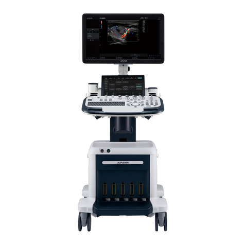
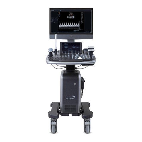
Alpinion Medical Systems E-CUBE 8 Diamond User manual

USER MANUAL
Rev. 6 (ENG)
70004854

Copyright and License
Reproducon, adaptaon, or translaon without prior wrien permission is prohibited, except as allowed under
the copyright laws.
The informaon contained herein is subject to change without noce.
The only warranes for ALPINION products and services are set forth in the express warranty statements
accompanying such products and services. Nothing herein should be construed as constung an addional
warranty. ALPINION shall not be liable for technical or editorial errors or omissions contained here in.
Prepared by:
ALPINION MEDICAL SYSTEMS Co., LTD.
4F, 15, Magokjungang 14-ro,
Gangseo-gu, Seoul, 07789, Republic of Korea
Telephone: +82 2 3777 8500 Fax: +82 2 3777 8691 www.alpinion.com
Copyright © ALPINION MEDICAL SYSTEMS Co., LTD, All rights reserved.
Revision Log
The following is a list of major changes and addions that have been made to this manual since it was rst
released.
Rev Date (YYYY/MM/DD) Descripon
Rev. 0 2019/01/22 User manual rst released
Rev. 1 2019/03/15 Updated for Rev. 1 release
Rev. 2 2019/08/27 Updated for Rev. 2 release
Rev. 3 2020/01/10 Updated for Rev. 3 release
Rev. 4 2021/12/15 Updated for Rev. 4 release
Rev. 5 2022/05/31 Updated for Rev. 5 release
Rev. 6 2022/10/14 Updated for Rev. 6 release

Table of Contents
1. System Basics............................................................................... 1-1
Introducon......................................................................................................... 1-2
System Components............................................................................................ 1-6
Peripherals and Accessories .............................................................................. 1-11
Image Display..................................................................................................... 1-17
Control Panel ..................................................................................................... 1-19
QWERTY Keyboard............................................................................................. 1-22
Touch Screen...................................................................................................... 1-23
Transducers........................................................................................................ 1-24
2. Geng Started ............................................................................ 2-1
Operang Requirements ..................................................................................... 2-2
Moving and transporng the system................................................................... 2-3
Powering On/O.................................................................................................. 2-6
Adjusng the Monitor and Touch Screen ............................................................ 2-8
Connecng/Disconnecng the Transducer ....................................................... 2-10
Acvang/Deacvang the Transducer ............................................................ 2-11
3. Starng a Study ........................................................................... 3-1
Paent Registraon ............................................................................................. 3-2
4. Imaging Modes............................................................................ 4-1
2D Mode.............................................................................................................. 4-2
M Mode ............................................................................................................. 4-18
Color Flow (CF) Mode ........................................................................................ 4-23
Power Doppler (PD) Mode................................................................................. 4-32
Pulsed Wave Doppler (PWD) Mode................................................................... 4-38
Connuous Wave Doppler (CWD) Mode........................................................... 4-47
Tissue Doppler Imaging (TDI) Mode .................................................................. 4-52
3D and 4D Modes .............................................................................................. 4-54

5. Imaging Funcons........................................................................ 5-1
Freezing Images ................................................................................................... 5-2
Zooming Images .................................................................................................. 5-3
Full Screen ........................................................................................................... 5-4
Screen Split .......................................................................................................... 5-5
CINE Images......................................................................................................... 5-6
Annotang Images............................................................................................... 5-7
Panoramic Imaging ............................................................................................ 5-13
Needle Vision™ Plus .......................................................................................... 5-17
Contrast Enhanced Imaging............................................................................... 5-19
Elastography ...................................................................................................... 5-22
Stress Echo......................................................................................................... 5-30
Cube Strain™...................................................................................................... 5-44
6. Managing Paent Informaon and Image .................................... 6-1
Clipboard ............................................................................................................. 6-2
Touch Clip ............................................................................................................ 6-4
E6-view ................................................................................................................ 6-5
DICOM Spooler .................................................................................................. 6-18
Printer................................................................................................................ 6-20
DVR .................................................................................................................... 6-21
7. Measurements and Reports......................................................... 7-1
Basics ................................................................................................................... 7-2
Abdomen ........................................................................................................... 7-34
Obstetrics........................................................................................................... 7-43
Gynecology ........................................................................................................ 7-82
Cardiology.......................................................................................................... 7-92
Vascular ........................................................................................................... 7-129
Urology ............................................................................................................ 7-142
Pediatrics ......................................................................................................... 7-149
Small Parts ....................................................................................................... 7-158
Breast............................................................................................................... 7-166
Musculoskeletal (MSK) .................................................................................... 7-173

Emergency Medicine (EM)............................................................................... 7-178
8. Transducer and Biopsy ................................................................. 8-1
Transducer ........................................................................................................... 8-2
Biopsy .................................................................................................................. 8-7
Transducer Accessories...................................................................................... 8-18
9. Preset ........................................................................................ 79-1
System Preset ...................................................................................................... 9-2
Image Preset...................................................................................................... 9-47
10. Care and Maintenance............................................................. 710-1
System Care and Maintenance .......................................................................... 10-2
Baery Care and Maintenance.......................................................................... 10-6
Transducer Care and Maintenance.................................................................... 10-7
11. Safety and Regulatory Informaon............................................. 11-1
Safety Summary................................................................................................. 11-2
Equipment Safety Informaon........................................................................... 11-3
Paent Safety Informaon................................................................................. 11-4
An11-Virus Program ........................................................................................ 11-5
Electrical Safety Informaon.............................................................................. 11-6
Transducer Safety Informaon .......................................................................... 11-7
Biopsy Safety Informaon.................................................................................. 11-9
System Symbols and Labels ............................................................................. 11-10
Regulatory Informaon.................................................................................... 11-14
Electromagnec Compability (EMC).............................................................. 11-17
Diagnosc Ultrasound Indicaons for Use Format.......................................... 11-22
Acousc Output............................................................................................... 11-43
12. Appendix ................................................................................... 12-1
Appendix A. Biopsy Guide.................................................................................. 12-2


1
Introducon........................................................................................................... 1-2
System Components.............................................................................................. 1-6
Peripherals and Accessories ................................................................................ 1-11
Image Display ...................................................................................................... 1-17
Control Panel....................................................................................................... 1-19
QWERTY Keyboard .............................................................................................. 1-22
Touch Screen ....................................................................................................... 1-23
Transducers ......................................................................................................... 1-24
This chapter describes the system overview and operator controls.
System Basics

1-2 System Basics
Introducon
System overview
The E-CUBE 8 ultrasound system provides excellent quality and reliability as well as these specic
features:
Table 1-1 System feature
Physical Dimensions
•Height: 1470/1560 mm
•Width: 532 mm
•Depth: 787 mm
•Weight: 55 kg (not including opons)
Clinical Applicaons
•Abdomen
•OB
•GYN
•Cardiology
•Small Parts
•MSK
•Vascular
•Urology
•EM
•TCD
•Breast
•Appendix
Available Imaging Modes
•2D mode
•Harmonic mode (HAR)
•M mode
•Color M mode
•Anatomical M mode (AMM)
•Color Flow Doppler (CF) mode
•Power Doppler (PD) mode
•Direconal PD mode
•Pulsed Wave Doppler (PWD) mode
•Connuous Wave Doppler (CWD) mode
•High PRF Doppler mode
•Tissue Doppler Imaging (TDI) mode
•3D/4D mode
Image Processing Technology
•Xpeed™
•Full SRI™
•Spaal Compounding Image (SCI)
•Panoramic
•Live HQ™
•Needle Vision™/Needle Vision™ Plus
•Contrast Enhanced Ultrasound (CEUS)
•ECG
•Elastography
•Filter Method Tissue Harmonic Image (FTHI)
•Pulse Inversion Tissue Harmonic Image (PTHI)
•Raw Data Processing
•Post Processing

Introducon 1-3
Operable Transducers
Pencil Doppler •CW2.0
•CW5.0
Linear Array •L3-12T
•L3-12H
•L3-12HWD
•L8-17H
•IO3-12
•IO8-17T
Sector Phased Array •SP3-8T
•P1-5CT
Convex Array •C1-6CT
•C5-8NT
•SC1-4H
•SC1-4HS
•SC1-6H
Endocavity •EV3-10T
•EC3-10T
•E3-10
Volume Convex •VC1-6T
Volume Endocavity •VE3-10H
Measurement Package
Including reports for:
•Abdomen
•OB
•GYN
•Cardiology
•Vascular
•Urology
•Pediatrics
•Small Parts
•Breast
•MSK
•EM
Basic Measurements
2D Mode •Distance, Ellipse, Trace
•Area, Circumference
•%Stenosis
•Volume
•Angle
•A/B Rao
•Volume Flow Area
Doppler Mode •Velocity
•Time
•PI
•Trace
•Acceleraon
•S/D Rao
•RI
•Auto Trace

1-4 System Basics
Basic Measurements (cont.)
M Mode •A/B Rao
•Distance
•Time
•Slope
•%Stenosis
•HR
Connecvity
•Vericaon
•DICOM storage
•DICOM print
•DICOM storage commitment
•DICOM media
•DICOM worklist
•DICOM MPPS
•DICOM Structured Report (OB-GYN)
•DICOM Structured Report (Echocardiography)
•DICOM Structured Report (Vascular)
•Cube View™
•Network Storage
•Wireless LAN (Opon)
User Interface
•English
•German
•French
•Spanish
•Italian
•Russian
•Portuguese
•Chinese

Introducon 1-5
Documentaon
CAUTION
Safety instrucons must be reviewed before operang the unit.
E-CUBE 8 documentaon consists of following manuals:
•The User Manual and Quick Guide (TRANSLATED) provides informaon needed by the user to operate
the system safely. It describes the basic funcons of the system, safety features, operang modes,
measurements/calculaons, transducers, and user care and maintenance.
•The Reference Manual (ENGLISH ONLY) contains data tables, such as Obstetric and Cardiology
references.
•The Service Manual (ENGLISH ONLY) supplies block diagrams, lists of spare parts, descripons,
adjustment instrucons or similar informaon which helps qualied technical personnel in repairing
those parts of the system which have been dened as repairable.
The E-CUBE 8 manuals are wrien for users who are familiar with basic ultrasound principles and
techniques. They do not include sonographic training or detailed clinical procedures.
NOTE
•The manuals are only provided in electronic format on the CD.
•The CD includes English and all translaons.
•The screen images in this manual are only for illustraonal purposes. Actual screen display may dier
slightly from that shown in this manual.
Contraindicaon
Using the system for certain purposes such as gender determinaon is severely restricted by law.
Do not operate the system for an ophthalmic purpose or any use aecng the paent’s eye by the
acousc beam.
Prescripon device
United States law restricts this device to sale or use by, or on the order of a physician.
Intended operator prole
The E-CUBE 8 is intended for use by a qualied and trained physician or sonographer with at least basic
ultrasound knowledge for ultrasound evaluaon.
The operator must have read and understood the user manual.

1-6 System Basics
System Components
Front view
There are the main components of your system:
2
4
8
9
10
1
3
5
6
7
Figure 1-1 Front view
No. Component No. Component
1Monitor (21.5-inch wide display) 6Control panel
2LED lamp 7Up/Down lever
3Gel warmer 8Handle
4Transducer holder 9Transducer cable holder
5Transducer holder 10 CW port

System Components 1-7
Rear view
1
43
5
2
Figure 1-2 Rear view
No. Component No. Component
1I/O panel 4ECG port
2AC outlet 5System on/o switch
3AC inlet
NOTE
When connecng an external monitor to your system, use the monitor with 1366 x 768 or higher resoluon.

1-8 System Basics
Side view
1
2
34
Figure 1-3 Side view
No. Component No. Component
1Monitor arm 3Caster lock
2Transducer port 4Caster
Peripheral area
In the middle of the system, you can place oponal peripherals such as black and white printer and color
printer.
CAUTION
The peripheral area is only for peripheral devices. Do not place transducers or the footswitch in the
peripheral area to prevent damaging them from accidentally falling o.

System Components 1-9
I/O panel
I/O panel located on the rear side of a system includes video input and output, audio input and output,
Ethernet, power and control connecons for a printer. See Figure 1-4 below for more details.
CAUTION
•Each outer (case) ground line of peripheral/accessory connectors are earth grounded. Signal ground lines
are not isolated.
•For compability reasons, use only ALPINION approved transducers, peripherals or accessories.
•Be sure to plug the power supply cable of the peripherals to the connector panel of the system to avoid
unexpected electrical shock.
•Do not connect any transducer or accessories without approval from ALPINION.
1211
9
8
10
1 2 3
4 5 6
7
Figure 1-4 I/O panel
No. Component No. Component
1B/W printer port 7VGA port
2Color printer port 8Audio in port (Reserved)
3S-Video input port (Rerserved) 9HDMI port
4Remote control port for a B/W printer 10 Audio out port
5
Remote control port for a color printer
11 USB ports (4 ports)
6S-Video output port 12 Ethernet port
NOTE
The external storage media such as USB HDD or DVD-RW should be connected with the system referring to
the following instrucons.
•If power consumpon of the external storage media corresponds to more than 0.5 A and less than 1 A, you
should use 3 or 4 port to get it acvated properly.
•If power consumpon of the external storage media exceeds 1A, you should use a Y-cable that makes the
external storage media receive power from two USB ports at the same me.

1-10 System Basics
CAUTION
•The connecon of equipment or transmission network other than as specied in these instrucons can
result in electric shock hazard.
•Connected peripherals must meet IEC standard (An equipment that processes data: IEC 60950/EN 60950,
a medical equipment: IEC 60601-1/EN 60601-1). For product conguraon, it must meet the safety
requirements of product standard IEC/EN 60601-1 or system standard IEC 60601-1-1/EN 60601-1-1.
•The operator shall not contact the parts (SIP/SOP) and the paent simultaneously.
•When connecng a cable to the ethernet (LAN) port, always use the oponal LAN isolator (EN-20G by
EMO system or any similar isolator complying with IEC/EN 60601-1) to protect your system from electrical
damage.

Peripherals and Accessories 1-11
Peripherals and Accessories
Before using the peripherals or accessories, you should consider the following requirements.
WARNING
Observe all warnings and cauons given in the operaon manual of peripheral device.
CAUTION
For compability reasons, use only ALPINION approved peripherals or accessories. DO NOT connect any
peripherals or accessories without approval by ALPINION.
Peripheral update for EU countries
The following is intended to provide the users in EU countries with updated informaon concerning the
connecon of the E-CUBE 8 to image recording and other devices or communicaon networks.
The E-CUBE 8 has been veried for overall safety, compability and compliance with the following on-
board image recording devices:
•Color Printer
Manufacturer: Sony Corporaon
Model: UP-D25MD, UP-25MD
•B/W Printer
Manufacturer: Sony Corporaon, Mitsubishi Electric Corporaon
Model: UP-D898MD, UP-X898MD, P95DE(P95DW)
•DVD-RW
Manufacturer: Hitachi-LG Data Storage, Inc
Model: GP50NW40
The E-CUBE 8 has also been veried for compability, and compliance for connecon to a local area
network (LAN) via the rear panel Ethernet connecon, provided the LAN components are IEC/EN 60950
compliant.
The E-CUBE 8 may also be used safely while connected to devices other than those recommended above
if the devices and their specicaons, installaon, and interconnecon with the system conform to the
requirements of IEC/EN 60601-1-1.

1-12 System Basics
Basic accessories
The E-CUBE 8 has the following basic accessories:
•E-CUBE 8 console •User Manual, Reference Manual (So copy)
•Sonic gel •Quick Guide (So copy)
Oponal supplies and accessories
The following tables show oponal supplies and accessories that have been veried to be compable
with the system.
Biopsy kit
•L3-12 Biopsy Starter Kit (for L3-12T, L3-12H)
•SC1-6 Biopsy Starter Kit (for C1-6CT, SC1-4H, SC1-6H)
•SC1-4HS Biopsy Starter Kit (for SC1-4HS)
•VE3-10H Disposable Needle Guide (for VE3-10H)
•VE3-10H Reusable Needle Guide (for VE3-10H)
•E3-10 Disposable Needle Guide (for E3-10)
•E3-10 Reusable Needle Guide (for E3-10)
•EN3-10 Disposable Needle Guide (for EV3-10T, EC3-10T)
•EN3-10 Reusable Needle Guide (for EV3-10T, EC3-10T)
Oponal funcon
•Full SRI •SRI •Elastography
•FTHI (Filtered Tissue Harmonic) •Auto IMT •Cube ViewTM
•Xpeed •CW •Needle Vision™
•Spaal compounding •Anatomical-M •Needle Vision™ Plus
•Value 3D/4D •Frequency Compounding •Auto NT
•CV M&R •Panoramic •Volume Advance
•DICOM 3.0 Connecvity •Tissue Doppler Image •Cube Note
•DICOM SR (OB) •Stress Echo •AutoEF
•DICOM SR (Adult Echo) •Cube StrainTM
•DICOM SR (Vascular) •Live HQTM
Console accessory
•Tri-pedal footswitch

Peripherals and Accessories 1-13
Footswitch (Opon)
The oponal tri-pedal footswitch that is connected with the rear panel of your system performs specic
funcons easily instead of pressing funcon keys on the control panel.
The each pedal of the footswitch may have dierent funcons depending on the assigned sengs such
as Freeze, P1, P2, P3, and Rec/Pause.
To assign the footswitch funcons, press the [System Preset] key and go to User Seng > Print/Foot
Switch.
Figure 1-5 Footswitch
CAUTION
Do not place or store the footswitch in the peripheral area on the system to prevent damaging the footswitch
from accidently falling o.
Wireless LAN (Opon)
A Wireless Network is available on the E-CUBE 8. For adjusng a wireless LAN connecon, see "Network"
on page 9-34.
Using unrecommended wireless LAN adapter may cause system malfuncon. To prevent system
malfuncon, only use wireless LAN adapters approved or recommended by ALPINION.
NOTE
Please contact your local agent to get the latest informaon on compable wireless LAN adapters.

1-14 System Basics
Baery (Opon)
This system uses lithium ion baeries. The lithium ion baery provides power if AC power is not
available.
NOTE
The baery is designed to work with E-CUBE 8 systems only. Use only the baeries authorized by Alpinion
Medical Systems.
The length of the me the system can run on the baery will vary, depending on the diagnosc mode
and the peripherals connected.
If the baery level runs low while using the system, connect it to an AC power source to recharge the
baery.
WARNING
•The baery has a safety device. Do not disassemble or alter the baery.
•Do not heat the baery or discard it in a re.
•Do not leave the baery in direct sunlight.
•Do not short-circuit the baery by directly connecng the negave terminals with metal objects.
•Do not subject baeries to mechanical shock.
•Do not use a damaged baery. If the baery emits an unusual odor or heat during use or recharging,
immediately stop using it and contact an authorized agent or an ALPINION MEDICAL service engineer.
CAUTION
•This system has an embedded baery. The baery used in the system must be replaced by an authorized
agent or an ALPINION MEDICAL service engineer.
•Ensure that water or liquids do not drip into the baery connecon area.
Table of contents
Other Alpinion Medical Systems Medical Equipment manuals