alpro Weekend-System II User manual

Information on processing regarding the workow and standard operation procedure (SOP) may be obtained at our website:
www.alpro-medical.de, or can be requested by e-mail: [email protected], or by phone: +49 7725 9392-0.
Installation Manual (for technicians)
Weekend-System II


3
Contents
I. Installation Manual
1. Basis cleaning of the water lines .................................................................... 4
2. Installation and connection of the Weekend-System II ................................. 5
2.1. Form of delivery ........................................................................................ 5
2.2. Positioning on the treatment unit ............................................................ 5
2.3. Connection to the treatment unit ........................................................... 5–6
2.4. Connection diagram ................................................................................ 7
2.5. Installation instructions ........................................................................... 8
3. Technical data .................................................................................................. 9
3.1. Technical data ......................................................................................... 9
3.2. Unit plan .................................................................................................... 10
3.3. Media plan ................................................................................................. 11
3.4. Spare parts ............................................................................................... 12
II. Operating Manual
1. User instructions ............................................................................................... 13
2. Symbols used on the product information, labels and instructions for use .. 13
3. Target group ...................................................................................................... 14
4. Intended purpose - intended use ..................................................................... 14
4.1. Weekend-System II .................................................................................. 14
4.2. Bilpron StarterSet ..................................................................................... 14
5. Application ........................................................................................................ 14
6. Basic cleaning with BRS®before installation ................................................. 15
7. Operating states of the Weekend System II ................................................... 16
8. Operation .......................................................................................................... 17–20
8.1. Switching the Weekend System II on and off ........................................ 17
8.2. Filling the tank ........................................................................................ 17
8.3. Timing of use ............................................................................................ 18–20
9. Maintenance ..................................................................................................... 21
10. Troubleshooting ................................................................................................ 22
11. Disposal notes .................................................................................................. 23
12. Report incidents .............................................................................................. 23

4
I. Installation Manual
(Exclusively for trained technical personnel)
The activities described below may only be carried out by dental equipment technicians
who have been specially trained and in compliance with the applicable regulations on
electrical safety and the drinking water regulations.
Regulation (EU) 2017/745 Annex I; para 14.1 Where a device is intended to be used in combination with
other devices or equipment, the combination, including the connections, shall be safe and shall not impair the
intended performance of the devices.
1. Basic Cleaning of the Water Lines
(exclusively for trained service technician)
The basic cleaning of the water lines with the Biofilm- Removing-Set
(BRS®) must not be carried out through the Weekend-System II!
BIOFILM-REMOVING-SET Application of the Biolm-Removing-Set (BRS®)
TheBiolm-Removing-Set(BRS®) is used to
removethebiolminthewaterlinesofthetreat-
ment unit. An application is required for treatment
units that have been in operation for more than one
year at the time of installation of the ALPRO-BCS
(BottleCareSystem) and must be carried out by a
service technician.
TheBiolm-Removing-Setcomeswithdetailed
instructions explaining the application step by step.
Completely remove all handpieces and contra--
angles, ultrasonic handpieces, multifunctional
syringes, etc., so that the water lines in these instru-
ments are not clogged by the cleaning process.
5-litre pressure tank system For basic cleaning of the water lines always use an
with connection for hose external pressure tank system from which the BRS®
6 mm/4 mm REF 8593 solutions are pumped into the waterways of
the treatment unit at a pressure of at least 2 bar.
For optimum results when using the BRS®, we
recommend the use of the ALPRO-BRS®recipro-
cating plunger type pump (REF 8593) and the ready-
made canister.

5
2. Installation and Connection of the Weekend-Systems II
2.1. Form of delivery
• Weekend-System II
• Connection cables
• Installation manual (for technical personnel)
• Operating manual
• Device passport and handover protocol
2.2. Positioning on the treatment unit
The positioning of Weekend-System II at the treat-
ment unit should be stated in particular cases. The
risk of stumbling or obstacle must be excluded.
After installation the Weekend-System II must be
accessible easily. In particular, it must be paid atten-
tionthatthetankcanbelledeasily.
2.3. Connection to the treatment unit
The Weekend-System II must only be connected by
an expert authorized by ALPRO in accordance with
the valid instructions for the drinking water decree.
In case of interference to the treatment unit, the
warranty conditions of the manufacturer have to be
followed.
For the connection of the air and water pipes please
use the pipes, T-pieces and couplings included in the
delivery contents.
a) Water supply
Asarule,thesupplyisconnectedwithaexiblemetal
tube (armoured tube included in delivery) directly
at the angle valve in the connection box of the treat-
ment unit. It can also be connected behind the lock
valve so that the Weekend-System II becomes
depressurised when switching off the treatment
unit!
If the water pressure in the incoming pipe is
higher than 6 bar, an appropriate water pressure
regulator must be assembled in front of the
Weekend-System II!

6
b) Water exit
The exit of Weekend-System II has to be connected
with the pipe of the treatment unit to the instru-
ments,tothetumblerllerandtothebowlrinsing.
Ifpossible,thisshouldbedonewithaexiblemetal
tube (included in delivery) which has to be connec-
ted directly with the central water supply of the
treatment unit.
If necessary, the pipes of the treatment unit to the
instruments,tothetumblerllerandtothebowl
rinsing are to be changed in the way that they are
connected together to a common string.
c) Compressed air entrance
The compressed air pipe (blue) of the Weekend-
Systems II should be connected into the treatment
unit. To do so, the compressed air pipe in the
treatment unit must be separated behind the
pressure control and a T-piece must be installed.
The pressure in this pipe must be at least 2 bar.

7
=
2.4. Connection Diagram
ALPRO Weekend-System II
Bowl rinsing Hand piecesTumblerller
If the water pressure in
the supply line is higher
than 6 bar, an additional
pressure regulator must
be installed in front oft he
Weekend-System II!
Water entrance
Water exit
(blue) compressed air
controlled max. 2 bar
Connection box
Connection with T-piece or coupling

8
2.5. Instructions for installation
Before installation, a basic cleaning should be carried out (see chapter 1. page 4)
a) Switch off power supply of the treatment unit
using the main switch!
b) Close angle valve in the connection box and
relieve the water pipe system of the treatment unit
of pressure, e.g. by operating the multifunctional
syringe.
c) Fix a position for the Weekend-System II.
(see chapter 2.2)
d) Seek a suitable entrace into connection box of
the treatment unit or prepare it yourself (diameter
approx. 30 mm).
e) Connect the connecting lines of the Weekend-
System II to the treatment unit as described in
chapter 2.3 and 2.4.
f) Unscrew the screw in the turning knob of the
water stopn and remove the turning knob.
Remember the position of the turning knob.
Remove the cover!
g) Fit the pipes for water and compressed air at the
Weekend-System II:
1. First screw the outgoing pipe on the middle
supply.
2.Afterwardsttheincomingpipetothewater
stop.
3. Last insert the plastic tube into the quick
coupling.
When installing the device in the practice, secure
withaatwrench(SW21)whenscrewingthewater
tubes to the device in order to prevent the
connections in the casing from being damaged.
h) Fit the cover and the turning knob again. Put the
turning knob into the same position as it was before
the dismantling (f)!
i) Open the angle in the connection box again and
switch on the main switch of the treatment unit.

9
3. Technical Data
3.1. Technical Values
Operating data
Filling amount: Min: 200 ml, Max: 900 ml
Microlter: 80µm(FilterF2)
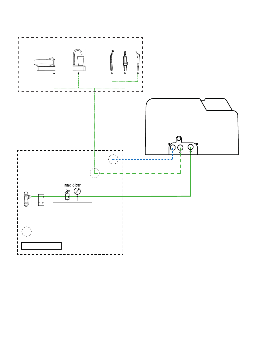
Connection data
Media: Compressedair:withoutoil,drainedandltered
Water: ltered(80µm)
Maximum admissible pressures: Air pressure in incoming pipes: max. 8 bar
Air pressure in the tank: 2 bar
Pressure of incoming water: max. 6 bar
Connection lines: Incoming air pipe: blue PE-/PA-tube
Measures and weight
Measurements
(without tubes): width x length x height: 20 cm x 29 cm x 18.5 cm
Weight (empty): approx. 2.5 kg
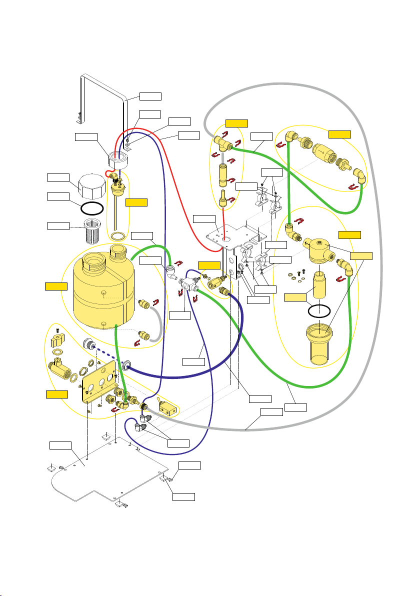
Material
Chassis: sheet steel, galvanized
Casing: acrylonitrile butadiene styrene copolymer (ABS)
Tank: high-density polyethylene (HDPE)
Screwes connections: Polyoxymethylene (POM), brass
Tubes: polyamide, polyethylene, high-grade steel
ALPRO-BCS*
Weekend-System II*
SN XXXXXX
Gerätepass und Übergabeprotokoll
Entwurf_Gerätepass_210930_DE Seite / page 2/2
REF 80300357_01_20211012_DE
Bitte beachten:
Installation (ISO13485:2016 – Pkt. 7.5.3) und Wartung (ISO13485:2016 – Pkt. 7.5.4) des Geräts hat
ausschließlich durch von ALPRO autorisierte S ervice-Technikerzu er folgen, ansonsten erlischt die
Gewährleistung.
Hinweis betrifft nur Weekend-System II:
Zwischen Wasseranschluss/ Behandlungseinheit und dem Weekend-System II muss unbedingt ein
Wasser-Feinfilter z.B. Praxis-Eingangsfilter (Maschenweite max. 80 µm) installiert sein! Andernfalls
können wir keine Gewährleistung übernehmen, wenn das Gerät aufgrund Verschmutzung in den
Leitungen ausfällt (nähere Informationen, siehe Handbuch)
ALPRO MEDICAL GMBH
Mooswiesenstr. 9
D-78112 St. Georgen/ Schwarzwald
Tel.: 0 77 25/93 92-0, Fax: 0 77 25/93 92 91
E-mail: alpro@alpro-medical.de
Internet: www.alpro-medical.de
Endkontrolle
ALPRO MEDICAL GmbH
______________ _________________
Datum Unterschrift
*zutreffendes Gerät bitte ankreuzen
ALPRO-BCS*
Weekend-System II*
SN XXXXXX
Gerätepass und Übergabeprotokoll
Entwurf_Gerätepass_210930_DE Seite / page 1/2
REF 80300357_01_20211012_DE
Prüfprotokoll : _______________
Funktionsprüfungen:
i. O.
Dichtigkeitsprüfungen:
i. O.
Montage-/Prüftermin :
Hiermit wird bestätigt, dass das
ALPRO-BCS*
Weekend-System II*
in der Praxis installiert wurde.
(Anschrift Zahnarztpraxis)
Am______________ an der Behandlungseinheit ______________________________________
(Datum)
(Marke / Standort / Zimmer)
Hersteller-konform angeschlossen und übergeben wurde. Das Personal, namentlich Frau /Herr
___________________ wurde in die Funktionen des Gerätes, siehe Bedienungsanleitung,
von der Fa.__________________________________________________________ eingewiesen.
(Fachhandel / Techn. Service)
Gekauft am:
_______________________________________ ________________________________
(Unterschrift / Stempel Fachhandel / Techn. Service) (Unterschrift / Stempel Zahnarztpraxis)
Aus Gründen der Gewährleistung und des Qualitätswesens gem. ISO
13485:2016 – Pkt. 7.5.3, bitten wir Sie, den Pass mit Protokoll
auszufüllen und eine Kopie an uns zurückzusenden. Vielen Dank!
*zutreffendes Gerät bitte ankreuzen
For warranty and quality reasons
according to ISO 13485:2016 - 7.5.3,
we kindly ask you to ll in the device
passport including the protocol and
return a copy to us as the manufacturer.
Thank you very much!

10
80700045
80770320
80710317
80770020
80770023
80710021
80770027
8250
80710023
80770314
82770043
80770130
80770840
80700057
80700013
80770170
80770840
80710047
80710048
80700017
80710046
80770092
80710047
8551
80700057
80710047
80770107
80700062
80700062
80770121
Explosionszeichnung Weekend-System II (für den externen Gebrauch)
29.06.2021
8559
8253
8254
8252
8255
8251
3.2. Device Diagram
(without housing)

11
Water stop Throttle valve Filter Check valve
Water supply
Air supply
Pressure control
Pressure valve
Check valve
Filler
neck
Strainer
Level indicator
Pressure tank
Water exit
Hand piece
(Tumbler + bowl rinsing)
3.3. Circuit Diagram

12
3.4. Spare parts
REF 8220 Installation kit
REF 8250 Pressure tank assembly
REF 8251 Water/air supply assembly
REF 8252 Pressure regulator assembly
REF 8253 Socket check valve assembly
REF 8254 Assembly group check valve
REF 8255 Assembly riser tube/tank
REF 8551 Sparepartwaterlter
Note:Whenchangingthelterelement,alsochangethesealingring
REF 8559 Conversionsetwaterlter

13
II. Operating Manual
1. User Instructions
Please attend to the following instructions in order to guarantee a trouble-free,
economic and safe work.
These instructions for use must always be available in the area of the unit. It must be
read and applied by every person who is assigned to work (installation, operation or
maintenance) on the unit.
2. Symbols used on the Product Information, Labels and Instructions
for Use
Please follow the instruction for use
Safety related information
Special features, the observance of which is necessary for the
perfect function of the device!
Use before (date of expiry) YYYY-MM
Batch number XXXXXX (six-digit)
Symbol for order number
Serial number XXXXXX (six-digit)
Health Industry Bar Code
CE symbol for Medical Devices of class I
CEsymbolwithNotiedBody(0123)forMedicalDevicesofclass
IIa, IIb or III (see declaration of conformity)
Fill level control symbol
Ifthemax.llinglevelisexceeded,thedevicemaybedamaged!
Donotoverlltank
Date of manufacture
Manufacturer, Company ALPRO MEDICAL GMBH, St. Georgen
Company logo of ALPRO MEDICAL GMBH, St. Georgen

14
3. Target Group
Trained technical staff.
4. Intended purpose - intended use
4.1. Weekend-System II
Add-on device for the supply of BILPRON into the service water lines of medical
and dental treatment units.
4.2. Bilpron StarterSet
Set for basic cleaning and disinfection of procedural waterlines of medical and
dental treatment units.
The Weekend System II may only be used as chair-side device for the supply of
BILPRON into the waterlines of dental treatment units.
The device may only be installed by technicians and operated by instructed and
trained specialist personnel. It must not be operated by the patient.
The Weekend System II may only be operated within the pressure areas
indicated. (Air pressure in inlet line: 3 – 8 bar; air pressure in the
tank: 2 bar; water inlet pressure: 2 – 6 bar).
BILPRON may only be used in devices that are compatible with it and must be
removedfromthelinesafterthespeciedcontacttime!
5. Application
TheBiolm-Removing-Set(BRS®)isusedtoremovethebiolminthewaterlinesofthe
treatment unit.
Application is required for treatment units that have been in operation for more than
one year at the time of installation of the Weekend System II and must be carried
outbyaservicetechnician.Thebiolmremovalsetcomeswithdetailedinstructions
explaining the application step by step.

15
Regulation (EU) 2017/745 Annex I; para. 14.1.
If the device is intended for use in combination with other devices or equipment the whole combination,
includingtheconnectionsystemshallbesafeandshallnotimpairthespeciedperformanceofthedevices.
The basic cleaning of the waterways with the Biolm Removing Set
(BRS®) must not be carried out with the Weekend System II
6. Basic cleaning with BRS®before installation
(Exclusively for trained technical personnel)
This activity may only be carried out by appropriately trained dental equipment
technicians in compliance with the applicable regulations on electrical safety and the
Drinking Water Regulations.

16
(see picture 1)
Water stop valve
Air supply
Pressure valve
Pressure tank
Water stop valve
Air supply
Pressure valve
Pressure tank
Water stop valve
Air supply
Pressure valve
Pressure tank
Water supply
Water supply
Water supply
Water exit
Hand piece
Tumbler
Bowl rinsing
Water exit
Hand piece
Tumbler
Bowl rinsing
Water exit
Hand piece
Tumbler
Bowl rinsing
7. Operating states of the Weekend-System II
7.1. Standby mode
(during the week)
Weekend-System II is switched off:
• Tap water flows freely
• Tank is without pressure, the tank
pressure valve blocks the air path
7.2. Injection of BILPRON
(Last working day before the weekend)
Weekend-System II is switched on:
• Tap water is stopped
• Tank is put under pressure
• BILPRON is injected
7.3. Time of effect
(during the weekend)
Weekend-System II is
switched off again:
• Tap water remains in a stopped position.
• BILPRON still remains in the lines without
pressure and has to be rinsed out after
the time of effect.
7.4. Rinsing/resting state
(First working day after the weekend)

17
8. Operation
8.1. Switching the Weekend System II on and off
The operating agents are on the side of the device, above the cover for the supplies.
You can switch the compressed air for the tank on
and off using the toggle switch of the pressure valve.
The com-pressed air must only be switched on when
BILPRON shall be injected into the treatment unit.
Prior to the injection of BILPRON, the procedural
water has to be stopped with the rotary switch of the
water stop (ball valve).
These operating instructions show the supplies in
the top view so that the positions of both switches
are visible in a better way.
The required positions for switching on and off are
identiedbythemarks„I“ und „0“ on the cover.
In the non-operation of the Weekend-System II all
switches have to be at „0“ as shown on the right.
The toggle for compressed air has always to be set on „0“ (pressure
release) after having nished the injection of BILPRON!
The rotary switch for water stop should always be closed in the evening!
8.2. Filling the tank
When the liquid level in the tank has dropped to „Min.“, the
tankhastoberelledagain!Thelevelindicatorisattheside
of the housing.
Only ll the tank up to the marking „Max.“!
The toggle switch of the tank pressure valve has to be set on
„0“afterrellingthetank.Whileopeningthetank,youheara
sibilance. This is normal as the compressed air escapes from
the tank.
Remove spilt BILPRON immediately with a damp cloth!
Only ll the tank so that the liquid does not cover more than up to the
bottom of the casingin lter!
Ifthelllevelistoohigh, liquid might enter the Weekend-System II via the air-relief valve and
might contaminate the inside of Weekend-System II!
Luft
Wasser
rotary switch
pressure valve
for air
Max.
n.N
Min.
N
air
water

18
Procedure
a) Check if enough BILPRON is in the tank:
The level indicator at
the side has to show
a liquid level at
„Max.“
b) Switch on Weekend-System II:
1. First turn off the water:
Set the water stop
(ball valve) on „I“.
2. Then pressurize the tank:
Set the toggle switch of
the pressure valve on „I“.
c) Adjust all instruments
tomaximumow
and remove them:
8.3. Timing of use
Before work breaks lasting several days: Initiate BILPRON.
Max.
n.N
Min.
N
2.
1.
Decontami-
nation:
Set all levers
on „I“
Remarks
Filling of the tank:
see chapter 7.2
The operating agents are on
the side cover.

19
Procedure
d) Each single procedural water line has to be
operated as long until the decontamination
agent “BILPRON” visibly comes out as blue
solution:
e) Switch off the treatment unit (if necessary at
the main switch!)
5x
Remarks
1. You should start with the
tumblerllerinordertoood
the main lines as soon as pos-
sible.Operatethetumblerller
several times.
2. Then continue with the
multifunctional syringes and
nallyrinsethelineswiththe
smallestow.
3. All instruments which are
additionally connected to the
dental unit (dental scaler,
powder jet devices etc.) have
also to be rinsed.
4. If the tank is empty, BILPRON
hastoberelledasdescribed
in chapter 7.2
The operating agents are on the
side cover.
l
l
l
l
l
l
l
l
l
l
l
l
min. 24 h
off

20
Remarks
The operating agents are on the
side cover.
The operating agents are on the
side cover.
Start again with the tumbler
llerandthemultifunctional
syringes in order to rinse the
main lines as soon as possible.
Rinse all instruments one after
another for approx. 3 minutes.
Record the decontamination
with BILPRON in the device
record book.
Procedure
f) Depressurize the tank: Set the
toggle switch of the pressure valve
on „O“.
Keep the water stop valve closed!
g) Switch on the treatment unit:
h) Turn the water on again:
Set the waterstop (ball valve)
on „O“.
i) Rinse each line until clear water comes out:
j)
Normal
operation:
Set all levers
on „O“
Ein
After work breaks of several days: rinse out BILPRON
1. 2.
10 x
on
Other manuals for Weekend-System II
1
Table of contents
Other alpro Medical Equipment manuals