Alps Electric SPEEDGLIDER User manual

Air Logic Power Systems, LLC
1745 S. 38th Street, Suite 100 Milwaukee, WI. 53215-1732
Phone: 414-671-3332 Fax: 414-671-6645
24 Hour Service Hotline: 800-325-8717
www.alpsleak.com and info@alpsleak.com
ALPS SPEEDGLIDER LINEAR
LEAK TESTER
ADVANCED OPERATOR
MANUAL

AIR LOGIC POWER SYSTEMS (ALPS) NOTICES
Notices:
Documentation
Air Logic Power Systems, LLC; (ALPS), reserves the right to make changes or improvements to the SpeedGlider ™
Linear Leak Tester at any time. These changes may not be immediately reflected in the manual accompanying your
system. If you notice any inaccuracies or oversights in this manual, please contact the ALPS Service Department.
This manual is protected by U.S. federal copyright laws © 2012 Air Logic Power Systems LLC. However, limited
permission is hereby granted to photocopy portions of this manual for training of company personnel only. No part
of this manual may be duplicated or transcribed in any form, for any other purpose, except as stated above, without
expressed written permission from Air Logic Power Systems LLC.
Software
Installation of any new or modification of existing software into the SpeedGlider ™ machine not approved by Air
Logic Power Systems LLC may adversely affect the operation or performance of the machine and possibly void the
warranty and or service agreements. Please consult Air Logic Power Systems Service Department prior to installing
or modifying existing software on this machine.
System Modifications
Mechanical or electrical modifications not approved by Air Logic Power Systems LLC to the SpeedGlider ™ system
may also void the warranty and/or service agreements. Please contact the Air Logic Power Systems Sales or
Service Department for approval or assistance with any machine modifications.
Trademark and Patent Acknowledgments
All products or product names mentioned in the manual are trademarks of their respective companies. The product
name: SpeedGlider ™ is protected under United States patent laws.
Contact Information
Service Department 24 Hour Hotline (US): 1-800-325-8717 (International): 011+800-325-8717
Service Manager, Ext. 199
Sales & Customer Service Support, Ext. 188
Sales Manager, Ext. 184
Air Logic Power Systems; LLC, Headquarters
1745 S.38th Street, Suite 100, Milwaukee, WI. 53215-1732
Phone: 414-671-3332 Fax: 414-671-6645
Email: www.alpsleak.com and: info@alpsleak.com
Copyright © 2012 by Air Logic Power Systems, LLC

AIR LOGIC POWER SYSTEMS (ALPS) TABLE of CONTENTS
Table of Contents
General Information 4
Machine Designation and Serial Number location ................................................................................................5
Hoisting and Transport of this Machine.................................................................................................................6
Safety 7
Safety: Warning Labels and Descriptions .............................................................................................................7
Safety: Warning Messages..................................................................................................................................10
Jokab Door Sensors: Positions ...........................................................................................................................11
Safety-Operational Status/Conditional Status.....................................................................................................12
Operational Status: Conditional status of the machine. ..................................................................................... 12
Glossary of Terms 13
SpeedGlider Advanced Operator 14
Advanced Operator Introduction .........................................................................................................................14
SpeedGlider Main Features.................................................................................................................................15
Viewing and editing HMI Displays.......................................................................................................................16
Password Protected Options and Settings..........................................................................................................16
Creating and changing On-Screen Variables, Values, and Settings ................................................................. 16
Changing settings and values using the TENKEY screen ................................................................................. 16
This Advanced Operator Manual Overview.........................................................................................................17
Theory of Operations 18
Leak Test Operations..........................................................................................................................................18
Pressure Decay Values and Percentages...........................................................................................................18
Container Handling..............................................................................................................................................19
Photo Eyes Introduction and Positions................................................................................................................19
Photo eye Function Table....................................................................................................................................19
Probe Carriage/Slide...........................................................................................................................................19

AIR LOGIC POWER SYSTEMS (ALPS) NOTICES
The Settings Menu 20
Settings Introduction............................................................................................................................................20
Test Pressures & Reject Limits Introduction .......................................................................................................20
Test Timers, Reject Limits & Test Pressures Navigation and Use......................................................................22
Probe Take Off Introduction ................................................................................................................................23
Probe Take Off Navigation and Use....................................................................................................................24
3 and 4 Head Probe Alignment .......................................................................................................................... 24
Container at test Photo Eye Alignment .............................................................................................................. 24
Recipes Introduction............................................................................................................................................27
Saving and Deleting Existing Recipes.................................................................................................................27
Creating a New Recipe........................................................................................................................................28
Load Recipe to Memory Card..............................................................................................................................29
Load Recipe from Memory Card to HMI..............................................................................................................30
Reject Timing Introduction...................................................................................................................................32
Reject Timing Navigation.....................................................................................................................................32
Machine Speeds Introduction..............................................................................................................................33
Speed Mode Description Table...........................................................................................................................33
Machine Speed Navigation and Information help Screens.................................................................................34
Photo Eye Settings Introduction..........................................................................................................................36
Photo Eye Settings Navigation............................................................................................................................36
Test Results Menu 37
Test Results Introduction.....................................................................................................................................37
Test Result Descritption Table ............................................................................................................................37
Last Test Detail Navigation..................................................................................................................................39
Last Detail Timers Navigation .............................................................................................................................39
Counters Navigation............................................................................................................................................39
Recent Rejects Navigation..................................................................................................................................40
Alarms Counters Navigation................................................................................................................................40
Alarm Log Navigation..........................................................................................................................................40
Maintenance Menu 41
Manual Test.........................................................................................................................................................41
Manual Test Display Description.........................................................................................................................42
Manual Test Navigation.......................................................................................................................................44
Input and Output Diagnostics..............................................................................................................................45
Input Diagnostics Navigation...............................................................................................................................45
About ...................................................................................................................................................................45
Supervisor Menu Introduction46
Supervisor Screen Flow and Navigation .............................................................................................................47
Supervisor Information Help Screens..................................................................................................................47
Container Change Over and Setup 48
Change Over Steps Overview.............................................................................................................................48
Change Over Steps Guide ..................................................................................................................................48
New Container Setup Guide for Test Settings ....................................................................................................52

AIR LOGIC POWER SYSTEMS (ALPS) GENERAL INFORMATION
SPEEDGLIDER ADVANCED OPERATOR MANUAL 4 TM 2012-005 REV00 © 10/25/2012
General Information
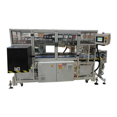
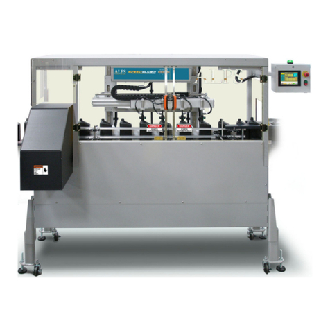
The SpeedGlider linear machine is designed for medium to high speed production lines requiring leak inspection. The
SpeedGlider is built to accommodate the customers’ conveyor equipment. Molded containers are captured and fed
into the test area by a timing screw located adjacent to the line conveyor. The timing screw, conveyer and test probes
are synchronized so that a smooth transition occurs from test cycle to test cycle. After the test is complete good
containers pass on, and defective containers are ejected off of the conveyor line.
A single electrical cabinet is installed on the backside of the machine containing the AC power circuits (variable
frequency drive, DC power supplies, power contactors, and main disconnect.

AIR LOGIC POWER SYSTEMS (ALPS) GENERAL INFORMATION
Machine Designation and Serial Number location
This individual machine is identified with an ID and Serial Number plaque affixed to the inside door surface of
the High Voltage control enclosure as shown below. Along with it are the 24 Hour service hotline phone number
and the UL Panel Rating plate.
LABEL
1 ALPS 24 hour service hotline phone number
2 UL Panel Rating Label
3 Identification and serial number plaque
4 UL Certification Sticker
5 UL Panel and Rating Label
4
5
3
1
2
4
5

AIR LOGIC POWER SYSTEMS (ALPS) GENERAL INFORMATION
Hoisting and Transport of this Machine
The SpeedGlider machine must be hoisted in the manner shown by a fork-lift. Forks must be of sufficient length to
support the entire machine. Warning! This machine has a high center of gravity. Do not transport with forks
tilted forward! Forks must remain parallel with the floor. A potential injury hazard exists as this machine can
overturn easily if caution is not observed. Refer to section 2 of the service and maintenance manual for procedures
relating to the transit of this machine to a new location.
The SpeedGlider Linear Leak Tester should be mounted on firm and level floor space. This machine comes with
various height settings. Verify that contact is solid and the machine is level at all four corners. Adjust all four feet as
shown to level the machine. Use a carpenter’s level to accomplish this.
Machine Weight:
1000 LBS.: Lift
from this side.
Optional
Height
settings
Adjustment
nut. Use a 1-
1/8” open-
end
or box
wrench to
adjust. Adjust
lower hex nut
beneath to
tighten foot.

AIR LOGIC POWER SYSTEMS (ALPS) SAFETY
SPEEDGLIDER ADVANCED OPERATOR MANUAL 7 TM 2012-005 REV00 © 10/25/2012
Safety
Safety: Warning Labels and Descriptions
Safety is critical at all times. The ALPS NGR Rotary machine is equipped with a full complement of warning
decals and labels. A standard series of warning and caution labels are in place to inform the operator of certain
hazards relative to the function of this machine. Please observe all of these warnings.
DANGER! ARC, SHOCK, AND FLASH HAZARD:
The potential for serious or fatal injury exists. Located on the outer door surface of the High-Voltage Control enclosure.
Do not open to explore or attempt to affect repairs in this area. In case of breakdown, initiate Lock-Out Tag-Out
procedures to secure the machine. Notify authorized personnel.
WARNING! LOW VOLTAGE CONTROL ENCLOSURE
This label is displayed on the outside of the Low Voltage Control enclosure. This area controls power to all electronic
modules on the machine. A potential for serious bodily injury or death exists. In case of breakdown, initiate Lock-Out
Tag-Out procedures to secure the machine. Notify authorized personnel.
RISK OF HOT SURFACES HAZARD
This symbol can be found in areas where a potential burn hazard exists. SpeedGlider servo motors have hot surfaces.
Do not touch motor surfaces while in operation or after being recently shut down.

AIR LOGIC POWER SYSTEMS (ALPS) SAFETY
Safety-continued
LOCK OUT / TAG OUT
This decal appears prominently next to the main power switch on the side of the High Voltage Control cabinet at the
rear of the machine. Lock-out and tag-out procedures are covered in the service and maintenance manual.
WARNING! WATCH YOUR HANDS AND FINGERS
This warning is seen on the front of the discharge chute. Do not thrust your hand up this chute while the machine is
operating. Contact with moving container material poses a slight to moderate threat of injury

AIR LOGIC POWER SYSTEMS (ALPS) SAFETY
Safety-continued
DANGER! DO NOT OPERATE WITHOUT GUARDS IN PLACE
This warning is located on the lower front portion and rear plexiglass guard of the machine. It cautions the operator not
to attempt to operate this machine without a plexiglass guard panel in place. The potential for severe injury exists while
the machine is operating. Please keep hands, long hair, low hanging jewelry, and loose clothing away from the moving
parts.
DANGER: STARTS AUTOMATICALLY
This warning is displayed on all plexiglass doors as a warning that the machine starts and stops automatically as a
function of its normal operating scheme.

AIR LOGIC POWER SYSTEMS (ALPS) SAFETY
Safety: Warning Messages
Note these Warnings and Cautions:
Cautions: Caution messages can appear before procedures. Messages of this type indicate possible damage to the
machine or loss of data if a step or procedure is not properly observed.
Warnings: Warning messages imply that a potential health hazard exists in the performance of any random
procedure.
THE SPEEDGLIDER LINEAR MACHINE USES 110/220 VOLTS AC POWER WHICH CAN CAUSE
SERIOUS INJURY OR DEATH ON CONTACT. DO NOT DEFEAT THE SAFETY FEATURES OF
THIS EQUIPMENT TO GAIN ACCESS TO INTERNAL VOLTAGES.
VOLTAGE HAZARD!
WARNING!
WARNING! DO NOT WEAR LOOSE CLOTHING, LOW-HANGNING JEWELRY, OR ANYTHING
THAT CAN BECOME ENTANGLED IN THE MOVING CONVEYOR. WOMEN ARE CAUTIONED TO
PIN UP LONG HAIR. THE POTENTIAL FOR SLIGHT TO MODERATE PERSONAL INJURY
EXISTS.
DANGER!
NEVER ATTEMPT TO SERVICE THIS MACHINE WITHOUT FIRST DISCONNECTING
ELECTRICAL AND PNEUMATIC POWER AND PERFORMING LOCK-OUT / TAG-OUT
PROCEDURES. THE POTENTIAL OF SERIOUS PERSONAL OR FATAL BODILY INJURY
EXISTS!
THE DETECTOR CONNECTED TO THE MOLDER ASSEMBLY MAY REACH A TEMPERATURE
SUFFICIENT TO CAUSE SECOND DEGREE BURNS. AVOID CONTACT WITH THESE
COMPONENTS DURING OPERATION OF THE SYSTEM.

AIR LOGIC POWER SYSTEMS (ALPS) SAFETY
Jokab Door Sensors: Positions
TABLE 1: Door Mounted Safety Switch Locations (from previous page).
ITEM COMPONENT FUNCTION
1 Jokab Door Switches Category 4 rated-pulsed signal non-contact switch. These work the
same as the one in the emergency stop on HMI touch screen panel.
2 Guard Assembly Protects personnel during operation from moving components that are
located inside the enclosure. Plexiglass doors and panels are
designed to limit access to the machine during operation. The doors
have safety interlocks which will stop the machine if a door is opened
while the machine is running. Both doors must be closed before the
machine can be restarted. The colored LED atop the HMI control box
will return to steady green.

AIR LOGIC POWER SYSTEMS (ALPS) SAFETY
Safety-Operational Status/Conditional Status
Operational Status: Conditional status of the machine.
TABLE 2: HMI Status LED: Color Code Indicates Running Status.
COLOR STATUS/CONDITION
Green Normal operating status.
Yellow Machine in bypass Mode or in Pause Condition
Red Machine stopped, door ajar or waiting for operator to press START. The circuit
is open, interrupted, e-stop has been pressed or a fault has occurred.

AIR LOGIC POWER SYSTEMS (ALPS) GLOSSARY of TERMS
SPEEDGLIDER ADVANCED OPERATOR MANUAL 13 TM 2012-005 REV02 © 03/19/2013
Glossary of Terms
TERM
DESCRIPTION
Encoder Generates digital electronic pulses that represent the position, speed of the
SpeedGlider
Air Preparation Unit
Cleans and regulates the incoming air supply, indicates a lockout valve, primary
particulate filter, coalescing filter, reject supply regulator, and an SpeedGlider supply
regulator.
Available Test Time
The calculated maximum amount of time to perform the leak test. This calculation is
based on the following factors: Max Fill Time, Test 1, Test 2, Probe-Retract and CPM
(containers per minute).
CPH/CPM
Containers Per Hour / Containers Per Minute
Downstream Photo-Eye
Photo-eye that senses a backlog of containers at the exit.
End of T1 Pressure Test result displays the pressure in the container at the end of Test 1.
End of T2 Pressure Test result displays the pressure in the container at the end of Test 2.
Fill Pressure
The pressure used to fill the container. This pressure is set in PSI.
Fast Speed Photo-Eye
When blocked by a backlog of containers, the SpeedGlider will accelerate to Fast
speed or decelerate to Normal speed when unblocked or when the backlog is cleared.
Fill Valve
The Solenoid valve that controls the air used to pressurize the container.
HMI An acronym meaning: Human Machine Interface. This is also referenced as the
Operator Touch Screen.
InWC (iWC)
Inches at water column. (One inch of water = 27.7 iWC = 1 PSI).
Manual Speed
Speed Mode where the SpeedGlider runs at a pre-set speed, regardless of the
backlog or the presence of containers.
PE
Acronym for Photo-eye. An electronic sensor for container status communication to
the PLC.
PLC An acronym for Programmable Logic Controller.
Recipe
A set of test setting values that can be saved and used for a particular container.
T1 Maximum
An acronym for Test 1 which refers to the maximum allowed pressure percent loss during test
one (T1).
T1 Minimum An acronym for Test 1 which refers to the minimum allowed pressure percent loss during Test
one (T1). Note: This is normally set to “0” as any container with a loss lower than this is
rejected.
T1 Pressure Loss
An acronym for Test results for Test 1 which refers to the total pressure loss during Test one
(T1).
T2 Maximum
An acronym for Test results for Test 2 which refers to the maximum allowed pressure percent
loss during test two (T2).
T2 Pressure Loss
An acronym for Test results for Test 2 which refers to the maximum during test two (T2).
Test 1 (T1) Time
Test 1 function where the applied pressure must reach the target pressure for the test to begin.
If target pressure is reached, the pressure loss must not exceed the maximum percentage
amount allowed during the allotted time or the container will be rejected.
Test 2 (T2) Time
Test 2 function begins when test 1 is completed and no rejects have occurred. During Test 2,
the pressure loss must not exceed the maximum percentage amount allowed during the
allotted time or the container will be rejected.
Test Leak Orifice
When performing a self-test, a pressure path to a test orifice is opened. The orifice size can
help determine the size of the leak that can be detected based on current test settings.

AIR LOGIC POWER SYSTEMS (ALPS) INTRODUCTION
SPEEDGLIDER ADVANCED OPERATOR MANUAL 14 TM 2012-005 REV02 © 03/19/2013
SpeedGlider Advanced Operator
Advanced Operator Introduction
Table 1-1: Basic Components
Ref # COMPONENT FUNCTION
1 Operator Display and
Touchscreen (HMI).
The (HMI) touchscreen includes controls for starting and
stopping the machine, guided or manual setup, and displays
machine status, counter, alarms, and fault conditions.
Contains the ON/OFF and e-stop palm buttons.
2
Reject Chute
Area where discarded containers are channeled.
3
Emergency Stop
E-Stop palm-button.
4
ON/OFF Switches
Controls ON/OFF operation of the machine.
5
LED Pictorial Display
Touch-screen command center.
Front View
2
1
3
4
5
2

AIR LOGIC POWER SYSTEMS (ALPS) INTRODUCTION
SPEEDGLIDER ADVANCED OPERATOR MANUAL 15 TM 2012-005 REV02 © 03/19/2013
SpeedGlider Main Features
Table 1-2: Operational Components
Item
COMPONENT
Function
1
Carriage/Slide: Test Probe Head
Main operating component where testing takes place.
2
Sense Line
Outgoing air line for pressure results.
3
Fill Line
Incoming air line for pressurized inflation.
4 Timing Screw
Advances, synchronizes, and spaces the containers for
test sequence.
5
Electrical Enclosure
Contains essential electronics to run the machine.
6
Airflow Shut-Off and Filter System
Airflow pressure control and filtration.
7
Main Power Switch
Controls incoming power to the machine.
4
1
3
2
SENSE
FILL
6
5
7

AIR LOGIC POWER SYSTEMS (ALPS) INTRODUCTION
SPEEDGLIDER ADVANCED OPERATOR MANUAL 16 TM 2012-005 REV02 © 03/19/2013
Viewing and editing HMI Displays
A password is required for viewing and editing some displays. If not previously logged in, when attempting to edit
or change settings a password login pop up box and keyboard will appear. The SpeedGlider ships with a default
password.
Password Protected Options and Settings
The options and settings features built into the SpeedGlider ™ are password-protected. This is done to
ensure that only authorized personnel have access to make
adjustments as required.
Steps:
1. Select an option from the HOME SCREEN.
2. A password prompt screen appears. Touch the white area.
3. Enter your PASSWORD and touch ENTER (ENT ) on the keypad screen at right.
4. Press OK.
Creating and changing On-Screen Variables, Values, and Settings
There are screen values and settings that can be changed from time to time.
Changing settings and values using the TENKEY screen
Steps:
1. Press on any grayed out information box.
2. Enter the new value at (INPUT) on the TENKEY keypad and press ENTER.
The new information is displayed. A built-in fail-safe prevents values from exceeding MINIMUM and
MAXIMUM limits. Touch CLR (clear) to clear an errant value. Touch BS (back space) to correct a mistake.
Click CANCEL to nullify entry. Note: Values in white background areas are readings and view only.
1. Sample password access sequence

AIR LOGIC POWER SYSTEMS (ALPS) INTRODUCTION
SPEEDGLIDER ADVANCED OPERATOR MANUAL 17 TM 2012-005 REV02 © 03/19/2013
This Advanced Operator Manual Overview
1. Theory of Operations
2. In-depth coverage on all the possible SpeedGlider Menu Sections
(procedures, navigation, and definition).
a. Settings Menu
b. Test Results Menu
c. Maintenance Menu
d. Supervisor Menu
3. Change Over and Setup
1/16 inch gap
Horizontal
Adjustment
Vertical
Adjustment

AIR LOGIC POWER SYSTEMS (ALPS) THEORY of OPERATIONS
SPEEDGLIDER ADVANCED OPERATOR MANUAL 18 TM 2012-005 REV02 © 03/19/2013
Theory of Operations
Leak Test Operations
Untested Containers are transferred from line conveyor to the
SpeedGlider through the timing screw. When 1 to 4 container(s) are
detected by the speed glider photo eye the probes will extend and fill
valves will execute simultaneously. At this time pressurization of the
containers occurs. During this process the containers are
electronically monitored to insure the sealed container reaches the
specified Peak Pressure. If any one of the containers fails to reach
peak pressure, that container will be rejected for a fill failure. A fill
failure usually occurs if there is a large hole or defect in the container.
If the container reaches target pressure then the SpeedGlider
performs Test 1.
TEST 1 (T1)-(Stabilize Test)
T1 is considered a pressure stabilization period. T1 is the time allowed
for pressure curve to flatten out. (See the graph below) Test 1 will
reject the container if Maximum % percent value for is exceeded. If
Maximum % value is not exceeded test 2 is performed.
Test 2 (T2)-(Leak Test)
Unlike test 1, test 2 is normally performed over a longer period time. (1 to 2 second range) This is done so that
smaller leaks can be detected. The graph below shows how time is relative to pressure loss in both good and bad
containers. Notice the pressure loss is more uniform or steady in T2 in relation to T1. In test 2 the container will be
rejected if the maximum % percent value is exceeded. If the T2 maximum % is not exceeded the container is
considered good. At the end of the test cycle the test probe is lifted and a probe retract timer begins. At the end
of this time period, the probe is considered to be retracted and the test cycle is completed.
Pressure Decay Values and Percentages
Unless otherwise specified the pressure values in the HMI displays are usually shown in Inches of Water Column
(iWC). This is done for scaling and calibration purposes as iWC units are on a much finer scale then PSI. For
general purpose and knowledge it should be known that one inch of water = 27.7 iWC = 1 PSI.

AIR LOGIC POWER SYSTEMS (ALPS) THEORY of OPERATIONS
SPEEDGLIDER ADVANCED OPERATOR MANUAL 19 TM 2012-005 REV02 © 03/19/2013
Container Handling
Containers transition from the production line conveyor into the SpeedGlider timing conveyor for leak testing.
During this transition containers will be monitored and controlled by various photo eyes, hold and reject
cylinders.
Photo Eyes Introduction and Positions
Photo eye Function Table
Photo Eye
Function
1. Container Present
Photo-Eye
Monitors the line of incoming containers to determine that a container is present to
initiate the test cycle. When a container is not present, station output will register a “no
container present” as a result
2. Slow/Stop Photo-
Eye
Senses when containers have cleared the sensor field. The sensor assumes there are
no more containers to be tested and shuts down the machine
3. Normal Photo-Eye
Controls machine speed. Reduces the machine speed from normal to slow speed when
the volume of containers has thinned-out or cleared the sensor field
4. Fast Speed Photo-
Eye
Accelerates the machine into fast speed when the sensor field is obstructed or broken
5. Downstream Jam
Photo-Eye
Temporarily pauses the machine when the sensor field is broken. It automatically
restarts the machine when the sensor field is clear
6. Reject
Verification/Chute
Monitor Photo-Eye
Verifies that rejected containers have left production line. If the sensor fails to detect the
container, or if the sensor field has not been broken after a reject occurs, the machine
and conveyor will shut down and an alarm condition called a Reject Verification Fault is
generated
Probe Carriage/Slide The probe carriage slide conveys the test
probes to the containers via a
magnetically driven servo motor. The
process begins with the container present
photo eye detect containers. Once
detected, the containers are transferred
into the timing screw. When containers are
at a specific point in the timing screw, the
probe carriage will begin its slide to allow
the test probes to seal the containers and
then apply test pressure to the containers.
Other manuals for SPEEDGLIDER
2
Table of contents
Other Alps Electric Test Equipment manuals

Alps Electric
Alps Electric FlexPitch User manual

Alps Electric
Alps Electric SC Linear Leak Tester User manual

Alps Electric
Alps Electric FlexPitch User manual

Alps Electric
Alps Electric FlexPitch User manual

Alps Electric
Alps Electric SPEEDGLIDER User manual

Alps Electric
Alps Electric FlexPitch User manual

Alps Electric
Alps Electric FlexPitch Instruction manual

Alps Electric
Alps Electric SPEEDGLIDER Instruction manual