Alps Electric SPEEDGLIDER User manual

STANDARD SPEEDGLIDER INSTALLATION MANUAL i TM 2012-014 REV00 © 8/6/2012
ALPS SPEEDGLIDER LEAK
TESTER FIELD
INSTALLATION MANUAL
Air Logic Power Systems, LLC
1745 S. 38th Street, Suite 100
Milwaukee, WI. 53215-1732
Phone: 414-671-3332 Fax: 414-671-6645
24 Hour Service Hotline: 800-325-8717
www.alpsleak.com and info@alpsleak.com


STANDARD SPEEDGLIDER INSTALLATION MANUAL i TM 2012-014 REV00 © 8/6/2012
Notices:
Documentation
Air Logic Power Systems, LLC; (ALPS), reserves the right to make changes or improvements to the standard
SpeedGlider™at any time. These changes may not be immediately reflected in the manual accompanying
your system. If you notice any inaccuracies or oversights in the manual, please contact the ALPS Service
Department.
This manual is protected by U.S. federal copyright laws © 2012 Air Logic Power Systems LLC. No part of this
manual may be duplicated or transcribed in any form, for any other purpose, except as stated above, without
expressed written permission from Air Logic Power Systems LLC.
Software
Installation of any new or modification of existing software in the SPEEDGLIDER not approved by Air Logic
Power Systems LLC may affect the operation or performance of the machine and possibly void the warranty
and or service agreements. Please consult Air Logic Power Systems Service Department prior to installing or
modifying existing software on this machine.
System Modifications
Mechanical or electrical modifications not approved by Air Logic Power Systems LLC to the SpeedGlider™
system may also void the warranty and/or service agreements. Please contact the Air Logic Power Systems
Sales or Service Department for approval or assistance with any machine modifications.
Trademark and Patent Acknowledgments
All products or product names mentioned in the manual are trademarks of their respective companies. The
name SpeedGlider™ is protected under copyright laws of the United States. SpeedGlider™ is a registered
patent and is protected by US patent laws.
Contact Information
Sales and service department personnel at Air Logic Power Systems, LLC:
Service Manager, Ext. 199
Sales & Customer Service Support, Ext. 188
Sales Manager, Ext. 184
Air Logic Power Systems, LLC. Headquarters
1745 S.38th Street, Suite 100, Milwaukee, WI. 53215
Phone: 414-671-3332 Fax: 414-671-6645
24 Hour Service Hotline: 800-325-8717
Email: info@ALPSLeak.com
Copyright © 2012 by Air Logic Power Systems, LLC

SPEEDGLIDER INSTALLATION MANUAL ii TM 2012-014 REV00 © 8/6/2012
Table of Contents
Notices: i
Documentation .......................................................................................................................................................i
Software Information ..............................................................................................................................................i
System Modifications..............................................................................................................................................i
Trademark and Patent Acknowledgments .............................................................................................................i
Contact Information................................................................................................................................................i
General Information 1
Introduction............................................................................................................................................................1
Warnings, Cautions, and Notes:............................................................................................................................1
Manual Hazards and Warning...............................................................................................................................1
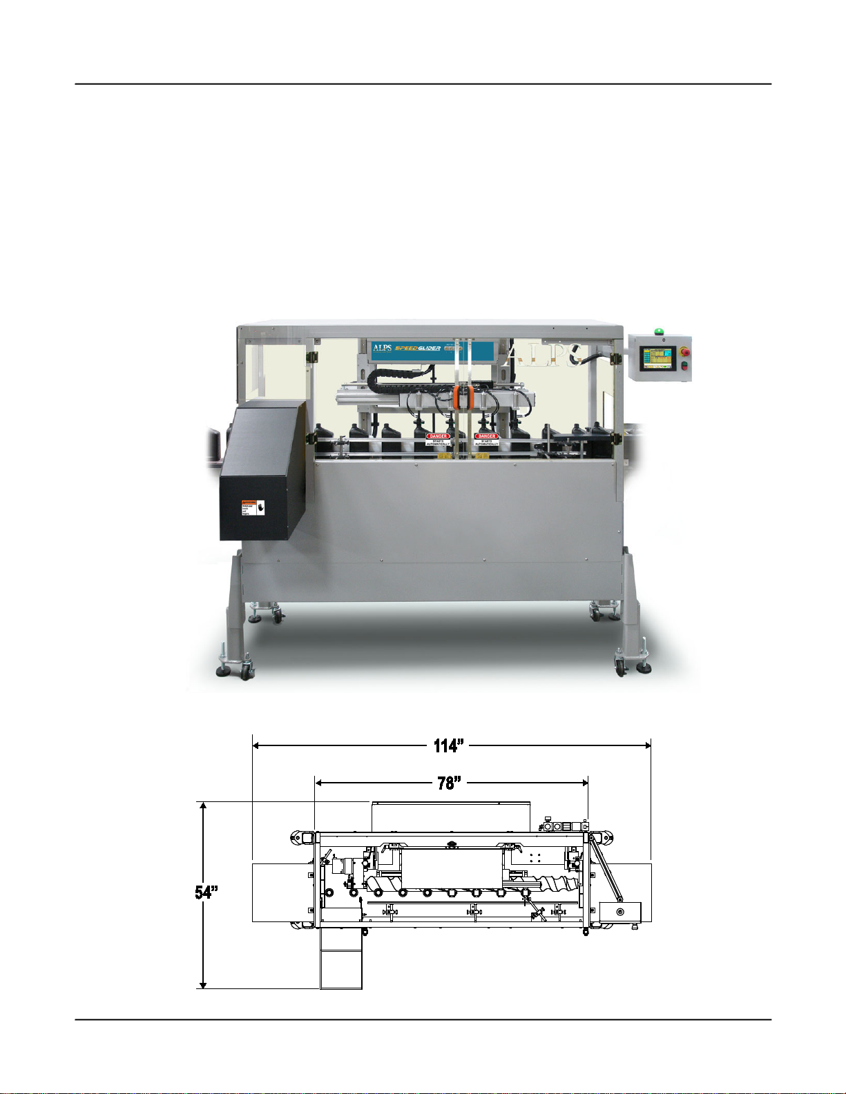
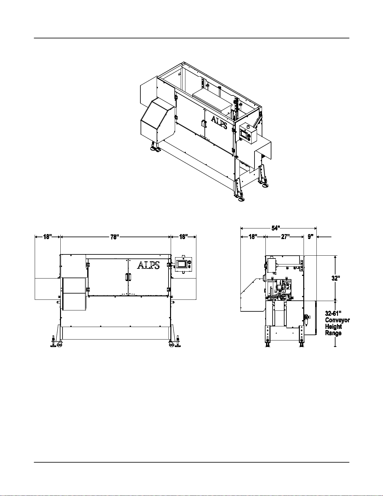
Linear Dimensions.................................................................................................................................................2
Section 1 Location, Installation, & Site Requirements3
Pneumatic Power Requirements: 120 PSI............................................................................................................3
Electrical Power Requirements: 110 VAC, 3Ø, 30A dedicated circuit..................................................................3
Air Supply: Minimum and Maximum air pressure..................................................................................................3
Section 2: Components Inventory 4
Common Components shipped with the SPEEDGLIDER.....................................................................................5
Section 3: Installation to Conveyor System 7
Hoist the SPEEDGLIDER machine from the pallet and install legs......................................................................7
Install Support Legs...............................................................................................................................................8
Transport the SPEEDGLIDER ..............................................................................................................................8
Installation to Conveyor System procedure ..........................................................................................................9
Front Panel Assembly .........................................................................................................................................11
Centering Probes over Conveyor........................................................................................................................13
Vertical Alignment to Conveyor...........................................................................................................................14
Leveling the machine ..........................................................................................................................................15
Install Rail Kit.......................................................................................................................................................19
Vertical Adjustment of Probe Carriage................................................................................................................20
Timing Screw Installation & Adjustment..............................................................................................................22

SPEEDGLIDER INSTALLATION MANUAL iii TM 2012-014 REV00 © 8/6/2012
Section 4: Installing Peripheral Devices 27
Photo-Eyes and Photo-Eye brackets ................................................................................................................. 27
Photo-Eyes: Placement and Positioning............................................................................................................ 27
Normal/Start Photo-Eye ..................................................................................................................................... 28
Fast Photo-Eye (Optional).................................................................................................................................. 28
Tuning Photo-Eyes............................................................................................................................................. 29
OPTEX DR-Q150TCN Sensor tuning and adjustment....................................................................................... 29
Change Mode
...................................................................................................................................................... 29
Change Mode Button Options............................................................................................................................ 30
Install Intake Tunnel Guards .............................................................................................................................. 31
Install Exit Tunnel Guards .................................................................................................................................. 32
Install Pressure Gauge....................................................................................................................................... 33
Section 5: Conveyor Railing 34
Rail Setup & Adjustment .................................................................................................................................... 34
Section 6: System Power-Up 35
Main Electrical Power Switch ............................................................................................................................. 35
Electrical Power Lockout/Tag Out.......................................................................................................................35
Airflow Control.................................................................................................................................................... 36
Air intake pressure gauge .................................................................................................................................. 36
Pneumatic Lockout/Tag Out................................................................................................................................36


SPEEDGLIDER INSTALLATION MANUAL 1 TM 2012-014 REV00 © 8/6/2012
General Information
Introduction
This manual is a guide on how to install the ALPS SpeedGlider Linear Leak Tester. A complementary listing of the
standard components shipped with the unit is also provided.
Warnings, Cautions, and Notes:
Note: Notation messages provide additional information or helpful tips about a topic.
Manual Hazards and Warning
The following hazards and cautions are found in this manual. Be sure to follow these instructions to ensure
safe setup and operation of the equipment.
BURN HAZARD
THE DETECTOR CONNECTED TO THE MOLDER ASSEMBLY MAY REACH A TEMPERATURE
SUFFICIENT TO CAUSE SECOND DEGREE BURNS. AVOID CONTACT WITH THESE
COMPONENTS DURING OPERATION OF THE SYSTEM.
VOLTAGE HAZARD
THE SPEEDGLIDER LINEAR MACHINE USES 110/220 VOLTS AC POWER WHICH CAN CAUSE
SERIOUS INJURY OR DEATH ON CONTACT. DO NOT DEFEAT THE SAFETY FEATURES OF THIS
EQUIPMENT TO GAIN ACCESS TO INTERNAL VOLTAGES.
DANGER!
NEVER ATTEMPT TO SERVICE THIS MACHINE WITHOUT FIRST DISCONNECTING ELECTRICAL
AND PNEUMATIC POWER AND PERFORMING LOCK-OUT / TAG-OUT PROCEDURES. THE
POTENTIAL OF SERIOUS PERSONAL OR FATAL BODILY INJURY EXISTS!
WARNING!
WARNING! DO NOT WEAR LOOSE CLOTHING, LOW-HANGNING JEWELRY, OR ANYTHING THAT
CAN BECOME ENTANGLED IN THE MOVING CONVEYOR. WOMEN ARE CAUTIONED TO PIN UP
LONG HAIR. THE POTENTIAL FOR SLIGHT TO MODERATE PERSONAL INJURY EXISTS.

AIR LOGIC POWER SYSTEMS (ALPS) GENERAL INFORMATION
SPEEDGLIDER INSTALLATION MANUAL 2 TM 2012-014 REV00 © 8/6/2012
ALPS SpeedGlider Linear Leak Tester:
General Information
The ALPS SpeedGlider™ is a multiple-station continuous-motion linear container leak tester intended for
inspection speeds up to 250 CPM (15,000 CPH).
The SpeedGlider 4.5 shown here is a four-station machine designed for containers ranging from
approximately 8 to 64 ounces (250ml to 2L); with container dimensions nominally up to 5” x 5” x 14” (127 x
127 x 355mm) tall.
The leak test probes are attached to a common carriage that is mounted to a servo-driven linear slide. The
servo automatically synchronizes with the timing screw motor through the use of an encoder. The control
system features a multi-channel PLC and color touch screen interface with an intuitive, icon-based menu
structure. Standard features include an integrated Self Test feature for each station.
Linear Dimensions (Top View)

AIR LOGIC POWER SYSTEMS (ALPS) GENERAL INFORMATION
SPEEDGLIDER INSTALLATION MANUAL 3 TM 2012-014 REV00 © 8/6/2012
Linear Dimensions of the SpeedGlider machine


SPEEDGLIDER INSTALLATION MANUAL 3 TM 2012-014 REV00 © 8/6/2012
Section 1-Location: Installation and Site
Requirements
Location: It is recommended that you:
1. Position the machine on a stable, flat surface.
2. Locate in a cooler area where the containers will remain at a lower temperature where the probe seal
will not stick. This over time results in more consistency in test results.
3. Avoid locating this machine anywhere near a blow molder or other heat source that could adversely
affect the temperature of container stock prior to test run. Test results can also be adversely affected.
Pneumatic Power Requirements: 120 PSI
Electrical Power Requirements: US: 110/220 VAC, 1Ø, 20A isolated circuit
EU: 110/220 VAC, 1Ø, 20A isolated circuit
Air Supply: A minimum of 80 psi. up to a maximum of 125 psi. steady output is required. (Actual pressure
may vary).
Conventional air regulator and filtration system
CAUTION
AIR SUPPLY MUST BE DRY AND NON-POLLUTED. CHECK TO SEE THAT THE AIRFLOW IS
FREE OF ANY FOREIGN SUBSTANCES; I.E. MOISTURE, OR ANY LIGHT LUBRICATING FLUIDS,
OR OTHER FOREIGN MATTER.
Plug in air
hose here.
Primary
Particulate
Filter
Coalescing
Air Filter
Reject Air
Regulator
Incoming Air
Regulator and
Pressure Gauge
1
3
2
1
Adjustment
knob

SPEEDGLIDER INSTALLATION MANUAL 4 TM 2012-014 REV00 © 8/6/2012
Section 2: Components Inventory
A standardized inventory of normal components shipped and installed with standard and field rotary
SPEEDGLIDER machines (2 listings). Verify that all components are present on-site.
REF
STANDARD COMPONENTS
DESCRIPTION
1 SpeedGlider (With tooling and devices installed)
2 Tunnel Guards
Set of (2) Plexiglass guards for entry and exit point of
SPEEDGLIDER
3 Hardware for Tunnel Guards (1 Bag) Set of (8) M8 screws, set of (8) M8 hex nuts.
4 Photo-eye Sensor/Detectors (Qty. 3) Normal, Slow, and Downstream photo-eyes. Installation
required when gate option is not present
5 Normal, Slow, Photo Eye Sensors;
mounting hardware and bracket Standard installation and placement is required
6 Legs Set of (4)
7 Pressure Gauge Qty. 1: Requires Installation to Air regulator
8 Installation Manual Installation Guide
9 Basic/Advanced Operations Manual Operational Guide
10 Service Manual/Electrical Schematics Maintenance Guide
11 Rail Kit One 5” section of twin railing with hardware kit
REF
OPTIONAL COMPONENTS
DESCRIPTION
12 Fast Speed Photo-Eye * Optional installation and placement is required
13 Keyence IB-1500 Laser-Height Unit *Optional electronic laser-height verification module: setup
14 DB-100 Downed Bottle Detector
*Optional electronic sensor to identify downed containers along
the conveyor line.
15 Spare Timing Screws *Optional for multiple processing.
16
17
18
19
20

AIR LOGIC POWER SYSTEMS (ALPS) SECTION 2 COMPONENTS INVENTORY
SPEEDGLIDER INSTALLATION MANUAL 5 TM 2012-014 REV00 © 8/6/2012
Common Components shipped with
the SpeedGlider
Common components boxed separately with shipment.
The following pages show a series of photos of commonly boxed and assembled components that should
come with a typical crated SpeedGlider shipment.
Tunnel Shielding:These come as a set, unboxed with the shipment. A single hardware bag contained within
and marked “J10751 Tunnel Hardware” comes with this installation. There are (12) M8 x 20mm Allen-Head
Capscrews and (12) Crimptite hex nuts. Use a 5mm Allen wrench for Capscrews and a 13mm open-end
wrench for the hex nuts.
Tunnel Shielding:-Qty. 2 (One set) and one hardware bag.
Set of Legs: These come secured to the pallet complete with their own mounting hardware. The hardware
here is used as a mounting device. Raise the unit from the back side with a fork lift to install legs.
Set of Tunnel Shields (2); Set of (4) Legs; bolted to pallet
M8 x 20 Allen
Capscrews
Qty: 12
M8 Hex nuts
Qty: 12

AIR LOGIC POWER SYSTEMS (ALPS) SECTION 2 COMPONENTS INVENTORY
SPEEDGLIDER INSTALLATION MANUAL 6 TM 2012-014 REV00 © 8/6/2012
Common Components
Timing Screw
The timing screw is shipped detached from the machine and packed separately. In some instances, more
than one timing screw may be included in this shipment to be used in other container applications.
The timing screw is packed separately and installed later.
Photo-Eyes and Photo-Eye brackets
Shown here are (4) photo-eye emitters (pre-assembled) and (3) pre-assembled reflectors. See section 4 for
installation and positioning. There are (3) positioned upstream of the timing screw: Fast, Normal, and Slow
photo-eyes and one downstream photo-eye just after the exit starwheel.
Left: Photo-Eye brackets with Emitter attached. Right: Brackets Photo-Eye Reflector attached.
One Railing Kit:
Rail kit comes with a set of (6) 6mm screws and lock nuts to attach to conveyor directly opposite the timing
screw.
Rail kit to be attached to conveyor: Rail is same length as timing screw.

SPEEDGLIDER INSTALLATION MANUAL 7 TM 2012-014 REV00 © 8/6/2012
Section 3: Installation to Conveyor System
Steps:
1. Hoist the SpeedGlider machine from the pallet and install legs
There are four brackets securing the SpeedGlider machine at each corner of the pallet. Dispose of the
brackets.
a. Unbolt the SpeedGlider machine from the pallet base.
b. Hoist the SpeedGlider machine from the back as shown and install all four legs.
c. Remove the pallet. Move the pallet a safe distance away where it is out of the way.
Hoist the SpeedGlider machine from the backside. For proper support, spread forks apart. Forks must
extend out the other side.
Note that this machine has a high center of
gravity, so stability is important. Be sure
that the forks extend out beyond the other
side of the machine. Tilt the forks back so that
the machine leans in toward the forklift.
WARNING!
MACHINE MUST BE HOISTED FROM THE BACK AS SHOWN BELOW. SPREAD FORKS APART! THIS
MACHINE HAS A HIGH CENTER OF GRAVITY. FORKS MUST SUPPORT THE ENTIRE GIRTH OF THIS
MACHINE. DAMAGE CAN OCCUR IF MACHINE IS NOT FULLY SUPPORTED FRONT AND BACK.

AIR LOGIC POWER SYSTEMS (ALPS) SECTION 3 INSTALLATION to CONVEYOR
SPEEDGLIDER INSTALLATION MANUAL 8 TM 2012-014 REV00 © 8/6/2012
Installation to Conveyor System
2. Install Support Legs-Adjust and Level the machine
With the SpeedGlider unit suspended in the air, install all four legs.
a. Adjust leveling feet-do not tighten yet.
b. Lower the SpeedGlider to the floor (supported by the leveling feet) and check adjustments with a
level. Raise the unit again as needed to make further adjustments as needed.
c. When it is determined that all adjustments have been made, raise the SpeedGlider unit and
transport to desired location. Use extreme caution. Make sure there is adequate space to
maneuver.
Install all four legs. Adjust leveling feet.
3. Transport the SpeedGlider:
4. Lower the SpeedGlider to the floor when it is in its designated location.
Optional Height
settings: Adjust
with a ¾ inch box
wrench or¾ inch
socket wrench.
Adjustable Foot
Use a 1-1/8 Open-
End Wrench

AIR LOGIC POWER SYSTEMS (ALPS) SECTION 3 INSTALLATION to CONVEYOR
SPEEDGLIDER INSTALLATION MANUAL 9 TM 2012-014 REV00 © 8/6/2012
Installation to Conveyor System
5. Uncouple and remove the Front Guard: Begin breaking down all electronic and sensor connections at
the front of the machine in preparation for disassembly. Begin by disconnecting both Jokab sensors at
the base of the front doors. Disconnect the Reject-Verification sensor at the reject chute. Secure all
lines to the inside body of the machine with tape. Do not allow to drag on the floor, damage may occur.
Left: Jokab door sensors. Right: Reject Verification sensor. Secure all cables with tape to inside surfaces.
6. Inside. With a 5mm Allen wrench, remove the following screws that secure the lower portion of the
front panel.
Inside the machine; remove these groups of fasteners. Use a 5mm Allen wrench.

AIR LOGIC POWER SYSTEMS (ALPS) SECTION 3 INSTALLATION to CONVEYOR
SPEEDGLIDER INSTALLATION MANUAL 10 TM 2012-014 REV00 © 8/6/2012
Installation to Conveyor System
7. At the upper left corner of the machine, remove this piece of Plexiglass to access the two screws behind
it. It is secured by (3) screws. Use a 5mm Allen wrench.
8. Plexiglass End-caps. Remove these two screws; one at each end. It is not necessary to remove the
plexiglass panels themselves. Use a 5mm Allen wrench.
Use an M5 Allen wrench.
Remove this piece of plexiglass.

AIR LOGIC POWER SYSTEMS (ALPS) SECTION 3 INSTALLATION to CONVEYOR
SPEEDGLIDER INSTALLATION MANUAL 11 TM 2012-014 REV00 © 8/6/2012
Installation to Conveyor System
9. Front Panel Assembly: Unfasten these screws and remove the entire panel assembly as shown in the
diagram below. Open doors to access screws behind. Use a 5mm Allen wrench. Enlist the aid of
another person to complete this step.
Use an M5 Allen
wrench to loosen.

AIR LOGIC POWER SYSTEMS (ALPS) SECTION 3 INSTALLATION to CONVEYOR
SPEEDGLIDER INSTALLATION MANUAL 12 TM 2012-014 REV00 © 8/6/2012
Installation to Conveyor System
Left: This is the SpeedGlider machine with the front guard removed. At this time, move the unit to its final
position along the conveyor.
10. Positioning the machine: With the machine lowered onto its set of wheels, gently move the
SpeedGlider machine to the conveyor system. The machine must be positioned perfectly parallel with
the conveyor.
Other manuals for SPEEDGLIDER
2
Table of contents
Other Alps Electric Test Equipment manuals

Alps Electric
Alps Electric SPEEDGLIDER User manual

Alps Electric
Alps Electric FlexPitch User manual

Alps Electric
Alps Electric FlexPitch User manual

Alps Electric
Alps Electric SC Linear Leak Tester User manual

Alps Electric
Alps Electric FlexPitch User manual

Alps Electric
Alps Electric FlexPitch User manual

Alps Electric
Alps Electric SPEEDGLIDER Instruction manual

Alps Electric
Alps Electric FlexPitch Instruction manual