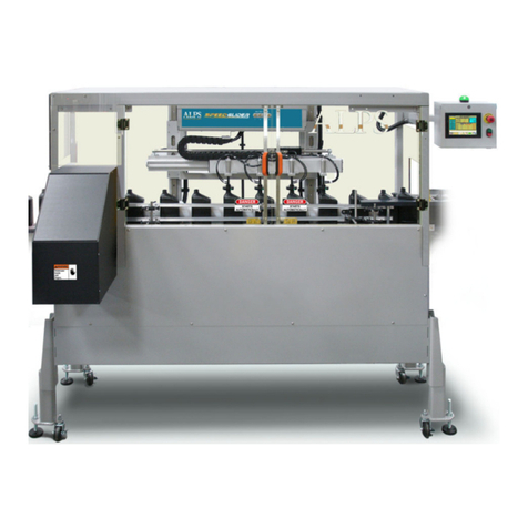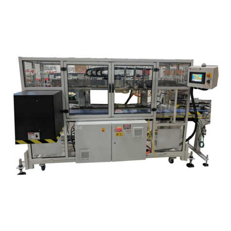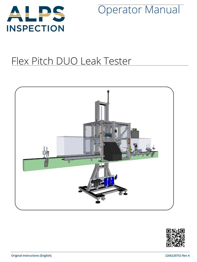
AIR LOGIC POWER SYSTEMS (ALPS) Flex Pitch
FLEX PITCH INSTALLATION MANUAL ii TM 2017-014 REV01 © 8/2/2017
Table of Contents
Notices: i
Documentation........................................................................................................................................................i
Software..................................................................................................................................................................i
System Modifications..............................................................................................................................................i
Trademark and Patent Acknowledgments .............................................................................................................i
Contact Information ................................................................................................................................................i
Copyright © 2017 by Air Logic Power Systems LLC..............................................................................................i
General Information 1
Introduction............................................................................................................................................................1
Warnings and Cautions .........................................................................................................................................1
ALPS Flex Pitch Multi-Moving Head Leak Tester .................................................................................................2
General Information................................................................................................................................. 2
Linear Dimensions (Top View) ................................................................................................................ 2
Linear Dimensions of the Flex Pitch machine .......................................................................................................3
Section 1: Location Site and Installation Requirements 4
Location .................................................................................................................................................................4
Electrical Power Requirements .............................................................................................................................4
Air Supply ..............................................................................................................................................................4
Section 2: Components Inventory 5
Common Components shipped with the Flex Pitch...............................................................................................6
Common components boxed separately with shipment.......................................................................... 6
Tunnel Shielding...................................................................................................................................... 6
Set of Legs............................................................................................................................................... 6
Common Components...........................................................................................................................................7
Photo-Eyes and Photo-Eye brackets ...................................................................................................... 7
Section 3: Installation to Conveyor System 8
Vertical Adjustment for Probe Carriage.............................................................................................................. 18
Section 4: Installing Peripheral Devices 20
Photo-Eyes and support brackets ...................................................................................................................... 20
1. Photo-Eyes and Photo-Eye brackets ............................................................................................. 20
2. Photo-Eyes: Placement and Positioning ........................................................................................20
3. Photo-Eyes: Mounting and Positioning on Conveyor.....................................................................21
Tuning Container Present and Reject Photo-Eyes............................................................................................. 21
Banner Q4X Laser Sensor Tuning and Adjustment..............................................................................21
Tuning Downstream Jam and Reject Verification Photo-Eyes........................................................................... 21
OPTEX DR-Q150TCN Sensor tuning and adjustment..........................................................................21
Change Mode Button Options...............................................................................................................22
Installing the Encoder to the Conveyor .............................................................................................................. 24


