Alps Electric FlexPitch Instruction manual

FLEX PITCH QUICK-START MANUAL i TM 2012-005 REV01 © 5/26/2016
ALPS
Air Logic Power Systems, LLC
2440 W Corporate Preserve Drive Unit 600
Oak Creek, WI 53154 - USA
Phone: 414-574-4151 Fax: 414-574-4152
24 Hour Service Hotline: 800-325-8717
www.alpsleak.com and info@alpsleak.com
FLEX PITCH LINEAR
LEAK TESTER
QUICK-START MANUAL
A quick reference guide for quick setup and startup.

AIR LOGIC POWER SYSTEMS (ALPS) NOTICES

AIR LOGIC POWER SYSTEMS (ALPS) NOTICES
Notices:
Documentation
Air Logic Power Systems LLC (ALPS), reserves the right to make changes or improvements to the Flex
Pitch™at any time. These changes may not be immediately reflected in the manual accompanying your system. If
you notice any inaccuracies or oversights in this manual, please contact the ALPS Service Department.
This manual is protected by U.S. federal copyright laws © 2017 Air Logic Power Systems LLC. However,
limited permission is hereby granted to photocopy portions of this manual for training of company personnel only.
No part of this manual may be duplicated or transcribed in any form, for any other purpose, except as stated above,
without expressed written permission from Air Logic Power Systems LLC.
Software
Installation of any new or modification of existing software into the Flex Pitch™ machine not approved by Air
Logic Power Systems LLC may adversely affect the operation or performance of the machine and possibly
void the warranty and or service agreements. Please consult Air Logic Power Systems Service Department
prior to installing or modifying existing software on this machine.
System Modifications
Mechanical or electrical modifications not approved by Air Logic Power Systems LLC to the Flex Pitch™
system may also void the warranty and/or service agreements. Please contact the Air Logic Power
Systems Sales or Service Department for approval or assistance with any machine modifications.
Trademark and Patent Acknowledgments
All products or product names mentioned in the manual are trademarks of their respective companies. The name
Flex Pitch™ is protected under copyright laws of the United States. Flex Pitch™ is a registered patent and is
protected by US patent laws.
Contact Information
Service Department 24 Hour Hotline (US): 1-800-325-8717 (International): 1-414-574-4151
Service Manager, Ext. 22180
Sales & Customer Service Support, Ext.
Sales Manager, Ext. 184
Air Logic Power Systems LLC, Headquarters
2440 W Corporate Preserve Drive Unit 600 Oak Creek, WI 53154 - USA
Phone: 414-574-4151 Fax: 414-574-4152
Email: www.alpsleak.com and info@alpsleak.com
Copyright © 2017 by Air Logic Power Systems, LLC

AIR LOGIC POWER SYSTEMS (ALPS) TABLE of CONTENTS
FLEX PITCH QUICK-START MANUAL ii TM 2012-005 REV01 © 5/26/2016
Table of Contents
Section 1: General Information 1
Machine Designation and Serial Number location ................................................................................................2
Section 2: Safety 3
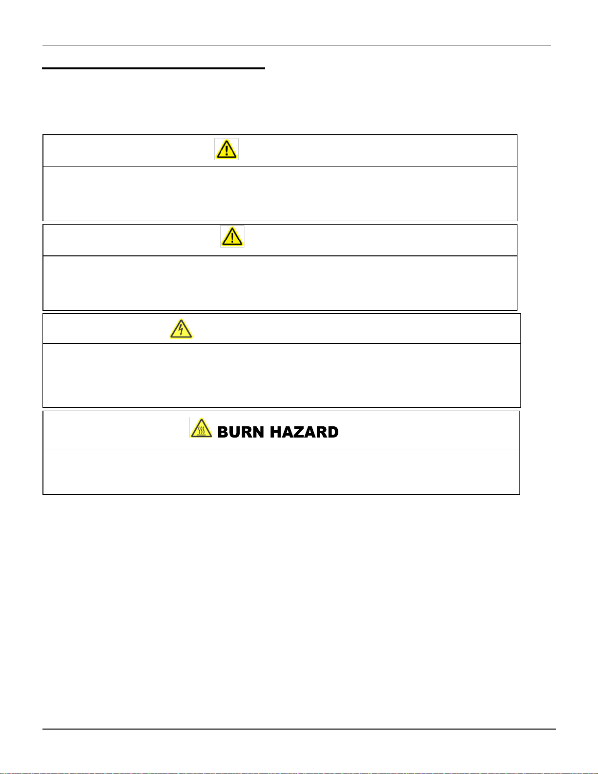
Safety: Warning Labels and Descriptions .............................................................................................................3
DANGER! ARC, SHOCK, AND FLASH HAZARD:................................................................................................3
RISK OF HOT SURFACES HAZARD...................................................................................................................3
LOCK OUT / TAG OUT.........................................................................................................................................4
WARNING! WATCH YOUR HANDS AND FINGERS...........................................................................................4
DANGER! DO NOT OPERATE WITHOUT GUARDS IN PLACE.........................................................................4
DANGER: STARTS AUTOMATICALLY................................................................................................................4
Safety: Warning Messages 5
Lockout-Tag Out Air supply..................................................................................................................... 6
Safety: Machine is installed and ready for production...........................................................................................7
HMI Emergency Stop Palm Button- ........................................................................................................ 7
Resetting an E-Stop ................................................................................................................................ 7
Section 3: Theory of Operations 9
Basic Theory of ALPS Leak Testing......................................................................................................................9
Theory of Operation- Photo Eyes..........................................................................................................................9
Positions and Functions: ......................................................................................................................... 9
Test Probes Carriage/Slide Introduction ............................................................................................... 10
Reject and Reject Verify PE’s Introduction............................................................................................ 11
Section 4: Getting Started 12
Main Electrical Power..........................................................................................................................................12
Air Supply ............................................................................................................................................................12
Air Supply Description Table...............................................................................................................................12
Air Pressure.........................................................................................................................................................12
Access Guards ....................................................................................................................................................13
E-Stops................................................................................................................................................................13
Container-Present and Reject Photo-Eyes .........................................................................................................13
Test Probe Carriage ............................................................................................................................................14
Reject Cylinder Position ......................................................................................................................................15
Section 5: Flex Pitch Quick Start Operations 16
About The Quick Start Manual ............................................................................................................................16
Section 6: HMI Control Panel Touchscreen Description 17
Section 7: HOME Screen and Main Menu Description 18
Home Screen Button Features and Functions TABLE........................................................................................18
Home Screen / Main Menu Directory Structural Hierarchy:................................................................................19
Section 8: Loading a Recipe 20
Recipes Menu Command Overview....................................................................................................................20
Section 9: Production 22

AIR LOGIC POWER SYSTEMS (ALPS) TABLE OF CONTENTS
Start Production...................................................................................................................................................22
Monitoring Production..........................................................................................................................................22
Production Quick-View.......................................................................................................................... 22
Accessing Online Information................................................................................................................ 22
Counters................................................................................................................................................ 23
Recent Results ....................................................................................................................................................23
Self-Tests.............................................................................................................................................................24
Recent Rejects ....................................................................................................................................................24
Cycle Timers........................................................................................................................................................25
Bottle Pressure....................................................................................................................................................25
Alarms..................................................................................................................................................................26
Alarms Introduction................................................................................................................................ 26
Loss of Air Alarm Servo Alarm ....................................................................................................... 26
Servo Communications Alarm Total Reject Percent Alarm............................................................. 26
Reject Verification Alarm....................................................................................................................... 27
H1 to H4 Consecutive Reject Alarms.................................................................................................... 28
H1 to H4 Transducer Alarms................................................................................................................. 28
Reject Percent Alarm H1 to H4............................................................................................................. 28
Auto Self-Test Alarm Chute Intrusion Alarm ................................................................................. 29
Container Present Photoeye Stuff OFF Container Present Photoeye Stuck ON.............................. 29
Controller Error Heads Failed to Home......................................................................................... 29
Heads Too Close Reject Photoeye Stuck OFF............................................................................. 30
Reject Photoeye Stuck ON.................................................................................................................... 30

AIR LOGIC POWER SYSTEMS (ALPS) GENERAL INFORMATION
FLEX PITCH QUICK-START MANUAL 1 TM 2012-005 REV00 © 10/16/2012
Section 1: General Information
The ALPS Flex Pitch Multi-Moving head leak tester provides high speed leak testing of a wide range of bottle
types including reverse-taper and small bottles which are traditionally difficult to test. The Flex Pitch has a smaller
footprint to perform leak testing on an existing conveyor line, requiring no line modifications. The Flex Pitch has
built in flexibility with 2-4 test heads for a variety of container sizes up to 350oz. This makes the Flex Pitch ideal
to leak test difficult containers. The Flex Pitch Multi-Moving head leak tester provides tool-less adjustments and
no formatted parts to change, making quick bottle changeovers. The Flex Pitch uses servo motors and linear
slide combination coupled with an encoder (mounted to the top of the conveyor) to track the conveyor movement
and speed. As molded bottles enter the machine, the Multi-Moving test heads locate and leak test each bottle.
After the test is completed, good bottles pass through machine, and defective bottles are ejected off the conveyor
line with a reason displayed on the HMI.
A single electrical cabinet is installed on the backside of the machine containing the AC power circuits, servo
motor drives, DC power supplies, power contactors, and main disconnect.

AIR LOGIC POWER SYSTEMS (ALPS) GENERAL INFORMATION
FLEX PITCH QUICK-START MANUAL 2 TM 2012-005 REV00 © 10/16/2012
Machine Designation and Serial Number location
This individual machine is identified with an ID and Serial Number plaque affixed to the inside door surface
of the control enclosure as shown below. Along with it are the 24-Hour service hotline phone number and
the UL Panel Rating plate.
Enclosure door: ID plaque, ALPS 24 Hour service phone number, and UL Panel rating label.
TABLE 1 Identification and rating labels.
LABEL
1 ALPS 24-hour service hotline phone number
2 ALPS ID
3 ALPS Rating Label
4 UL Certification Sticker

AIR LOGIC POWER SYSTEMS (ALPS) SAFETY
FLEX PITCH HMI 4.0.4 LEAK TESTER S/N 10751 3 TM 2012-005 REV00 © 7/24/2012
Section 2: Safety
Safety: Warning Labels and Descriptions
Safety is critical at all times. The ALPS NGR Rotary machine is equipped with a full complement of warning
decals and labels. A standard series of warning and caution labels are in place to inform the operator of certain
hazards relative to the function of this machine. Please observe all warnings.
DANGER! ARC, SHOCK, AND FLASH HAZARD:
The potential for serious or fatal injury exists. Label is located on the outer door surface of the control enclosure.
Do not open to explore or attempt to affect repairs in this area. In case of breakdown, initiate Lock-Out Tag-Out
procedures to secure the machine. Notify authorized personnel.
RISK OF HOT SURFACES HAZARD
This symbol can be found in areas where a potential burn hazard exists. Flex Pitch servo motors have hot
surfaces. Do not touch motor surfaces while in operation or after being recently shut down.

AIR LOGIC POWER SYSTEMS (ALPS) : SAFETY
FLEX PITCH QUICK-START MANUAL 4 TM 2012-005 REV00 © 10/16/2012
LOCK OUT / TAG OUT
This decal appears prominently next to the main power switch on the side of the control cabinet at the rear of the
machine. Lock-out and tag-out procedures are covered in the service and maintenance manual.
WARNING! WATCH YOUR HANDS AND FINGERS.
This warning is seen on the front of the discharge chute. Do not thrust your hand up this chute while the
machine is operating. Contact with moving container material poses a slight to moderate threat of injury
DANGER! DO NOT OPERATE WITHOUT GUARDS IN PLACE
This warning is located on the lower front portion and rear plexiglass guard of the machine. It cautions the
operator not to attempt to operate this machine without a plexiglass guard panel in place. The potential for
severe injury exists while the machine is operating. Please keep hands, long hair, low hanging jewelry, and
loose clothing away from the moving parts.
DANGER: STARTS AUTOMATICALLY
This warning is displayed on all plexiglass doors as a warning that the machine starts and stops automatically
as a function of its normal operating scheme.

AIR LOGIC POWER SYSTEMS (ALPS) : SAFETY
FLEX PITCH QUICK-START MANUAL 5 TM 2012-005 REV00 © 10/16/2012
Safety: Warning Messages
Note these Warnings and Cautions:
Cautions: Caution messages can appear before procedures. Messages of this type indicate possible damage to the
machine or loss of data if a step or procedure is not properly observed.
Warnings: Warning messages imply that a potential health hazard exists in the performance of any random
procedure.
WARNING!
WARNING! DO NOT WEAR LOOSE CLOTHING, LOW-HANGNING JEWELRY, OR ANYTHING
THAT CAN BECOME ENTANGLED IN THE MOVING CONVEYOR. WOMEN ARE CAUTIONED TO
PIN UP LONG HAIR. THE POTENTIAL FOR SLIGHT TO MODERATE PERSONAL INJURY
EXISTS.
DANGER!
NEVER ATTEMPT TO SERVICE THIS MACHINE WITHOUT FIRST DISCONNECTING
ELECTRICAL AND PNEUMATIC POWER AND PERFORMING LOCK-OUT / TAG-OUT
PROCEDURES. THE POTENTIAL OF SERIOUS PERSONAL OR FATAL BODILY INJURY
EXISTS!
THE DETECTOR CONNECTED TO THE MOLDER ASSEMBLY MAY REACH A TEMPERATURE
SUFFICIENT TO CAUSE SECOND DEGREE BURNS. AVOID CONTACT WITH THESE
COMPONENTS DURING OPERATION OF THE SYSTEM.
THE FLEX PITCH LINEAR MACHINE USES 220 VOLTS AC POWER WHICH CAN CAUSE
SERIOUS INJURY OR DEATH ON CONTACT. DO NOT DEFEAT THE SAFETY FEATURES OF
THIS EQUIPMENT TO GAIN ACCESS TO INTERNAL VOLTAGES.
VOLTAGE HAZARD!

AIR LOGIC POWER SYSTEMS (ALPS) : SAFETY
FLEX PITCH QUICK-START MANUAL 6 TM 2012-005 REV00 © 10/16/2012
Safety Lockout Tagout:
Lockout-Tag Main Power
Lock main Power in the OFF position when the machine is down for maintenance
.
Lockout-Tag Out Air supply
Lock airflow in the OFF position when the machine is down for maintenance

AIR LOGIC POWER SYSTEMS (ALPS) : SAFETY
FLEX PITCH QUICK-START MANUAL 7 TM 2012-005 REV00 © 10/16/2012
Safety: Machine is installed and ready for production
Jokab Emergency Stop devices: The ALPS Flex Pitch™Linear machine is equipped with a pair of door
sensor devices that will stop the machine in the event that one or both enclosure doors are opened during
operation. These are positioned front and center at the base where the doors intersect.
Jokab door-mounted e-stops: Left: Front View. Right: Close up view of left door
HMI Emergency Stop Palm Button-
The Flex Pitch™is equipped with two emergency stop (E-Stop) palm-buttons: one located on the HMI panel and
one located on the control enclosure. The E-Stop button has an LED to indicate the status of the safety system or
sensor.
Steady Green indicates the machine is either ready to run or is running production
Steady Red indicates that the circuit is open or interrupted, the E-stop has been pressed or a fault has
occurred.
Red/green indicates that the circuit has been opened by another series-connected sensor (door or other E-
Stop).
Resetting an E-Stop
When an e-stop condition occurs (door switch not made or e-stop button pushed), the following screen will show
on the HMI. The RESET E-STOP ALARM button will not appear until all e-stops are placed in the safe state.
Check and reset all door switches and e-stop buttons, until button appears. Then push the button to reset the e-
stop condition.

AIR LOGIC POWER SYSTEMS (ALPS) : SAFETY
FLEX PITCH QUICK-START MANUAL 8 TM 2012-005 REV00 © 10/16/2012
Safety: Operational Status/Conditional Status
Operational Status: Conditional status of the machine.
TABLE 2: HMI Status LED: Color Code Indicates Running Status.
COLOR
STATUS/CONDITION
Green Normal operating status.
Yellow Machine in bypass Mode, in Pause Condition or a warning has occurred
Red Machine stopped, door ajar or waiting for operator to press START. The circuit
is open, interrupted, e-stop has been pressed or a fault has occurred.
Clear (No Color) Waiting for run or start condition.

AIR LOGIC POWER SYSTEMS (ALPS) THEORY of OPERATION
FLEX PITCH HMI 4.0.4 LEAK TESTER S/N 10587 9 TM 2012-005 REV00 © 7/24/2012
Section 3: Theory of Operations
Basic Theory of ALPS Leak Testing
The product detect photo eye monitors the line for incoming containers to determine that a container is entering the
machine. The machine waits for the probe take-off delay when the container is under the appropriate head to initiate
the test cycle. When the test cycle begins, the Flex Pitch test probes will extend and fill valves will execute
simultaneously pressurizing the containers. During this process, the container is electronically monitored to ensure the
sealed container reaches the specified test settings for the recipe loaded on the Flex Pitch. If the container fails the
leak test, it will be rejected and the reason will be reported on the HMI.
Theory of Operation- Photo Eyes
Positions and Functions:
1. Container Present Photo-Eye: Monitors the line for incoming containers to determine that a container is
present to initiate the test cycle. The Container Present Photo-eye works in conjunction with the Probe Take-off
to ensure correct timing for the test probes. Adjusting the Probe Take-off is discussed further in the Advanced
Operator Manual.
2. Downstream Jam Photo-Eye: Temporarily idles (pauses) the machine when the sensor field is broken. It
automatically restarts the machine when the sensor field is clear.
3. Reject Photo-Eye: Detects a failed bottle and fires the reject cylinder at the appropriate time. It is also used to
detect untested bottles that may have been missed by the Container Present Photo-eye (issues an
Unexpected Container Warning).
4. Reject Verification: Verifies that rejected containers have left production line. If the sensor fails to detect the
container, or if the sensor field has not been broken after a reject occurs, the machine and conveyor will shut
down and an alarm condition called a Reject Verification Fault is generated.
Note: Reject Verification Failure: Any defective containers must be removed from the line manually

AIR LOGIC POWER SYSTEMS (ALPS) : THEORY of OPERATION
FLEX PITCH QUICK-START MANUAL 10 TM 2012-005 REV00 © 10/16/2012
Test Probes Carriage/Slide Introduction
Probe Carriage (slide)
The probe(s) detect leaks by monitoring air pressure inside the containers during tests. The probe(s) can detect
defective containers by sensing either sudden or gradual changes in pressure.
The test settings (parameters) can be fine-tuned for specific types of containers that have different volumes,
shapes, and wall material. Changes in pressure will determine which containers are accepted or rejected. Test data
on rejects is recorded in total numbers as a percentage of the total tests. The data can be used to adjust the
production process to reduce the number of rejects. When test settings (parameters) for a particular container are
set, they can be stored as a recipe and recalled later.
Important: Please do not attempt to service the probe carriage or attempt any modifications. Contact the
24 –hour ALPS SERVICE HOTLINE for help with service questions.

AIR LOGIC POWER SYSTEMS (ALPS) : THEORY of OPERATION
FLEX PITCH QUICK-START MANUAL 11 TM 2012-005 REV00 © 10/16/2012
Reject and Reject Verify PE’s Introduction
Reject Cylinder
When a container is deemed defective the Reject Cylinder will eject the defective container from the line.
Secondary Reject Nozzle (optional)
The Secondary Reject Nozzle will blow air and eject all containers, when the system is in alarm.
Reject Verify Photo-Eye (optional)
When the container is defective, a reject cylinder kicks it off the line. The container is supposed to fall through the
reject chute and into the reject bin. The reject verify PE detects the container being ejected. If the rejected container
fails to break the reject verify photo-eye beam, then a reject verification fault occurs, and the machine will stop. If
the container became lodged on the conveyor or the reject cylinder was defective the container can be retrieved
and disposed of it in the proper manner. The Reject, Secondary Reject, and Reject Verification can be enabled or
disabled in the Settings screen for Reject Verification.
Note: If a Reject Verification Failure occurs, any defective containers must be removed from
the line manually!
Reject Verification Photo-Eye
Reject
Verification
Sensor
Reject
Verification
Reflector
Reject Cylinder

AIR LOGIC POWER SYSTEMS (ALPS) GETTING STARTED
FLEX PITCH QUICK-START MANUAL 12 TM 2012-005 REV00 © 7/24/2012
Section 4: Getting Started
Ensure the Following Tasks are Complete:
Main Electrical Power Switch on
The main power switch is located at the front of the enclosure.
Air Supply
Hook up air supply and make sure Air on/off switch is in the on position
The Air Sensor and Regulator unit is on backside of machine.
Air Supply Description Table
Air Pressure Verify
The gauge should be set to 80 psi. Turn the
adjustment ring to vary the outgoing air pressure
ITEM FEATURE DESCRIPTION
1 Primary Particulate Filter. Cleans and regulates incoming, compressed air
supply.
2 Coalescing Air Filter Cleans and regulates incoming, compressed air
supply.
3 Incoming Air Regulator Manual regulator for the main air supply.
ON
(I)
OFF
(0)

AIR LOGIC POWER SYSTEMS (ALPS) GETTING STARTED
FLEX PITCH QUICK-START MANUAL 13 TM 2012-005 REV00 © 7/24/2012
Access Guards
Make sure they are closed.
E-Stops
Verify both e-stops are reset (pulled out) and the e-stop condition is reset on the HMI.
Container-Present and Reject Photo-Eyes
Adjustment
From recipe to recipe, the container present photo-eye and reject eye may require adjusting to accommodate
different size containers.
To adjust the photo eyes, loosen the hand clamp device and adjust vertically to the scale reading indicated by the
recipe.
Left: Container Present Photoeye Middle: Reject Photoeye

AIR LOGIC POWER SYSTEMS (ALPS) GETTING STARTED
FLEX PITCH QUICK-START MANUAL 14 TM 2012-005 REV00 © 7/24/2012
Test Probe Carriage
Ensure the probes are set to the proper height.
First unlock the slide by loosening the hand clamps on the left and right.
Adjust the slide height using the manual crank until the slide scale reading matches the recipe.
Retighten the slide lock hand clamps when finished adjusting the height.

AIR LOGIC POWER SYSTEMS (ALPS) GETTING STARTED
FLEX PITCH QUICK-START MANUAL 15 TM 2012-005 REV00 © 7/24/2012
Reject Cylinder Position
The Reject Cylinders position can be adjusted in and out. To adjust the reject cylinder, loosen the hand clamp
device and adjust horizontally to the scale reading indicated by the recipe.
Other manuals for FlexPitch
4
Table of contents
Other Alps Electric Test Equipment manuals

Alps Electric
Alps Electric SPEEDGLIDER User manual

Alps Electric
Alps Electric FlexPitch User manual

Alps Electric
Alps Electric FlexPitch User manual

Alps Electric
Alps Electric FlexPitch User manual

Alps Electric
Alps Electric SC Linear Leak Tester User manual

Alps Electric
Alps Electric FlexPitch User manual

Alps Electric
Alps Electric SPEEDGLIDER User manual

Alps Electric
Alps Electric SPEEDGLIDER Instruction manual