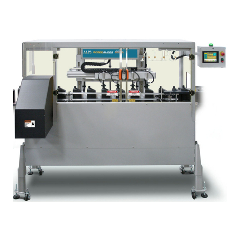
Alps Electric SC Linear Leak Tester User manual

Air Logic Power Systems, LLC
1745 S. 38th Street, Suite 100 Milwaukee, WI. 53215-1732
Phone: 414-671-3332 Fax: 414-671-6645
24 Hour Service Hotline: 800-325-8717
www.alpsleak.com and info@alpsleak.com
ALPS SC LINEAR LEAK
TESTER QUICK-START GUIDE
A beginner’s guide for quick setup and startup.

AIR LOGIC POWER SYSTEMS (ALPS) TABLE of CONTENTS
i
Table of Contents
Notices:...............................................................................................................................................................................i
Documentation .......................................................................................................................................................i
Software..................................................................................................................................................................i
System Modifications..............................................................................................................................................i
Trademark and Patent Acknowledgments .............................................................................................................i
Contact Information:...............................................................................................................................................i
Copyright © 2012 by Air Logic Power Systems, LLC.............................................................................................i
General Information ..........................................................................................................................................................i
General Description of the SC Linear Leak Tester machines................................................................................i
Machine Designation and Serial Number location .................................................................................................i
Statement of the intended use for this machinery.................................................................................................ii
Scope and Limits of Use........................................................................................................................................ii
Hoisting and Transport Machine ...........................................................................................................................ii
Installing the SC Linear Machine...........................................................................................................................ii
Wheel-Lock and Mounting Feet Adjustment ........................................................................................................ iii
SAFTY................................................................................................................................................................................ii
Safety: Warning Messages....................................................................................................................................ii
Cautions.................................................................................................................................................................ii
Warnings................................................................................................................................................................ii
Machine is Installed and ready for production......................................................................................................iii
Operational Status: Conditional status of the machine........................................................................................iii
HMI Emergency Stop and main Air Shut off.........................................................................................................iv
Theory of Operation .........................................................................................................................................................1
Theory of ALPS Leak Testing ...............................................................................................................................1
Theory of SC Production Operations ....................................................................................................................2
Getting Started..................................................................................................................................................................3
...............................................................................................................................................................................3
SC Quick Start Operations ..............................................................................................................................................4
About The Quick Start Manual ..............................................................................................................................4

AIR LOGIC POWER SYSTEMS (ALPS) TABLE of CONTENTS
Home Screen/Main Menu.................................................................................................................................................5
Touch Screen Controls and Menu Overview.........................................................................................................5
Boot Screen.......................................................................................................................................................... 5
Home Screen Features Overview.........................................................................................................................6
Settings Menu........................................................................................................................................................7
Guided Setup ....................................................................................................................................................................8
Guided setup Introduction .....................................................................................................................................8
Regarding the guided setup tool ...........................................................................................................................8
Guide Setup Procedures.......................................................................................................................................8
Guided Setup-Mechanical Instructions..................................................................................................................9
Manual Setup ......................................................................................................................................................10
1. Setting the Probe Height ..........................................................................................................................10
2. Setting up the Rails...................................................................................................................................11
3. Setting the Reject Cylinder.......................................................................................................................12
4. Rough Setting of the Photo-Eye...............................................................................................................12
Setting the Hold Cylinder.....................................................................................................................................13
Probe Regulator Setup:.......................................................................................................................................13
Guided Setup-Skip Mechanical Instructions (Auto Setup) Option.......................................................................13
Guided Setup-Fill Regulator Setup and Guided Setup Help...............................................................................15
Guided Setup: Reporting Times and Guided Setup Help ...................................................................................16
Set Conveyor Speed ...........................................................................................................................................17
Fine Tune the Photo-Eye.....................................................................................................................................18
Measure Move Time............................................................................................................................................18
SS Guided Setup: Set Reject Position................................................................................................................19
SS Guided Setup: Set up Measure, Move, and Stop Time.................................................................................19
Setting the T1 Value............................................................................................................................................20
Guided Setup- Start Leak Test Analysis and Setup Help ...................................................................................20
Gather Leak-Test Data........................................................................................................................................21
Leak Test Analysis ..............................................................................................................................................21
Leak Test Analysis-continued .............................................................................................................................22
End of Guided Setup: Screens A thru D..............................................................................................................23
Recipes............................................................................................................................................................................24
Introduction to Recipes........................................................................................................................................24
When to Load a Recipe.......................................................................................................................................24
Loading a Recipe.................................................................................................................................................24
Load Existing Recipe.......................................................................................................................................... 25
AIR LOGIC POWER SYSTEMS (ALPS) TABLE of CONTENTS
Production.......................................................................................................................................................................26
Stopping and Starting leak Testing .....................................................................................................................26
Emergency Stop Button.......................................................................................................................................26
Monitoring Production..........................................................................................................................................27
Self Test Procedure............................................................................................................................................ 27
Alarms Information ............................................................................................................................................. 28

AIR LOGIC POWER SYSTEMS (ALPS) NOTICES
i
Notices:
Documentation
Air Logic Power Systems, LLC; (ALPS), reserves the right to make changes or improvements to the SC at any time.
These changes may not be immediately reflected in the manual accompanying your system. If you notice any
inaccuracies or oversights in this manual, please contact the ALPS Service Department.
This manual is protected by U.S. federal copyright laws © 2012 Air Logic Power Systems LLC. However, limited
permission is hereby granted to photocopy portions of this manual for training of company personnel only. No part
of this manual may be duplicated or transcribed in any form, for any other purpose, except as stated above, without
expressed written permission from Air Logic Power Systems LLC.
Software
Installation of any new or modification of existing software in the SC Linear Leak Tester not approved by Air Logic
Power Systems LLC may adversely affect the operation or performance of the machine and possibly void the
warranty and or service agreements. Please consult Air Logic Power Systems Service Department prior to installing
or modifying existing software on this machine.
System Modifications
Mechanical or electrical modifications not approved by Air Logic Power Systems LLC to the SC leak detection
system may also void the warranty and/or service agreements. Please contact the Air Logic Power Systems Sales
or Service Department for approval or assistance with any machine modifications.
Trademark and Patent Acknowledgments
All products or product names mentioned in the manual are trademarks of their respective companies. The product
name: SC Linear Leak Tester is protected under the United States patent laws.
Contact Information:
Sales and service department personnel at Air Logic Power Systems, LLC.
Service Manager, Ext. 199
Sales & Customer Service Support, Ext. 188
Sales Manager, Ext. 184
Air Logic Power Systems; LLC, Headquarters
1745 S.38th Street, Suite 100, Milwaukee, WI. 53215-1732
Phone: 414-671-3332 Fax: 414-671-6645
24 Hour Service Hotline: 1-800-325-8717
Email: www.alpsleak.com and: info@alpsleak.com
Copyright © 2012 by Air Logic Power Systems, LLC

AIR LOGIC POWER SYSTEMS (ALPS) GENERAL INFORMATION
i
General Information
General Description of the SC Linear Leak Tester machines
The SC model linear machines are designed to test containers for leaks and other defects at speeds up to 180
BPM/CPM (bottles/containers per minute). The speed capability depends on container size, volume, and the
sensitivity in leak detection. The SC machines use an index motor and to advance the bottle and test it as it
moves on the conveyor. One or more photo-electric sensors are used to track and test containers.
Machine Designation and Serial Number location
This machine is identified with an ID and Serial Number label affixed to the inside HMI control box as shown at
left. At right is a label with the 24 Hour service hotline phone number. The ALPS 24-Hour Service Hotline is also
found inside of the front cover page along with sales and customer service phone numbers.
HMI control box.
HMI control box: serial number and ID label; ALPS 24 Hour service phone number label.
TABLE 1 Identification and rating labels.
LABEL
1 Identification and serial number
2 ALPS 24 hour service hotline phone number
1
2

AIR LOGIC POWER SYSTEMS (ALPS) GENERAL INFORMATION
ALPS SC LINEAR QUICK-START GUIDE ii REV00 © 02/12/2014
Statement of the intended use for this machinery
ALPS machinery is built solely for the intended purpose of pressure testing plastic containers, bottles, canisters, and
seals for leakage. In most instances, this is a precautionary step that is done before the container is filled with product.
In instances where the product is pre-packaged, leak testing is done to pressure-test the integrity of the sealing agent. A
positively sealed or leak proofed container eliminates the possibility of contamination of the product which keeps foods,
beverages, and pharmaceuticals safe for consumers. Conversely positively sealed and leak proofed containers for
petrochemical products and cleaning agents eliminates the possibility of the product contaminating the outside world.
With these types of products failure at any stage in the manufacturing process, without post leak detection, can result in
product being exposed to the environment. In some cases this may be cause for environmental concerns.
In particular the SC model linear machines are designed to test containers for leaks and other defects at speeds up to
180 BPM/CPM (bottles/containers per minute). The speed capability depends on container size, volume, and the
sensitivity in leak detection.
Scope and Limits of Use
The machine featured in this manual is designed to work with and inspect containers.
•Do not make any adjustments to this machine to process anything other than this product
•Do not run unstable or volatile materials through this machine
•Do not run parts made from any type of materials that are prone to ignite or explode at working temperature
•Do not run hot or recently molded materials exceeding 150°F (65.6°C) through this machine
Hoisting and Transport Machine
The SC linear machines can be handled manually by two or more individuals. The SC machine can be raised onto its
set of wheels and be moved to accommodate any conveyor line.
Installing the SC Linear Machine
Avoid installing this machine downstream from a nearby heat source, such as a blow-molding machine. Containers
should be at their coolest state in order for the testing to progress smoothly and without caps sticking to the seal during
the testing process.

AIR LOGIC POWER SYSTEMS (ALPS) GENERAL INFORMATION
ALPS SC LINEAR QUICK-START GUIDE iii REV00 © 02/12/2014
Wheel-Lock and Mounting Feet Adjustment
Position the SC machine on a flat and level area of flooring. The SC machine mounting feet can be adjusted
independently (inset) to raise it off the caster wheels to gain stable footing. Use a leveling tool to assure perfect
vertical alignment. To use the caster wheel option, engage the brake lever on each wheel to prevent movement.
SC Base
(Shown in transport mode).

AIR LOGIC POWER SYSTEMS (ALPS) SAFETY
ii
SAFTY
Safety: Warning Messages
Cautions
Caution messages can appear before procedures. Messages of this type indicate possible damage to the machine or loss of
data if a step or procedure is not properly observed.
Warnings
Warning messages imply that a potential health hazard exists in the performance of any random procedure
WARNING!
WARNING! DO NOT WEAR LOOSE CLOTHING, LOW-HANGNING JEWELRY, OR ANYTHING
THAT CAN BECOME ENTANGLED IN THE MOVING CONVEYOR. WOMEN ARE CAUTIONED TO
PIN UP LONG HAIR. THE POTENTIAL FOR SLIGHT TO MODERATE PERSONAL INJURY
EXISTS.
DANGER!
NEVER ATTEMP TO SERVICE THIS MACHINE WITHOUT FIRST DISCONNECTING
ELECTRICAL AND PNEUMATIC POWER AND PERFORMING LOCK-OUT / TAG-OUT
PROCEDURES. THE POTENTIAL OF SERIOUS PERSONAL OR FATAL BODILY INJURY
EXISTS!
THE DETECTOR CONNECTED TO THE MOLDER ASSEMBLY MAY REACH A TEMPERATURE
SUFFICIENT TO CAUSE SECOND DEGREE BURNS. AVOID CONTACT WITH THESE
COMPONENTS DURING OPERATION OF THE SYSTEM.

AIR LOGIC POWER SYSTEMS (ALPS) SAFETY
ALPS SC LINEAR QUICK-START GUIDE iii REV00 © 02/12/2014
Machine is Installed and ready for production
Operational Status: Conditional status of the machine
A single multi-color light exist on the SC leak tester to indicate the operational status
Normal Operation-Green Light
The system is built to monitor itself while in normal operational mode. If no Alarm condition exists and the
system is in run mode the Green light is illuminated.
Cautionary Condition-Amber Light
Indicates the machine is in BYPASS MODE or in a paused condition. The Amber light indicates the
existence of a continuous alarm condition-(i.e., auto self-test did not pass).
Warning Alarm Condition-Red Light and Audible Alarm
Typically, a system alarm will trip and display a fault condition on screen when a fault has been detected.
The HMI touch screen will show why the alarm was sounded. The operator then must acknowledge the
condition by changing the operating mode to STOPPED,to reset and allow the system to clear the
default. Below is shown a LOSS OF AIR Pressure alarm condition. The machine will not return to
NORMAL RUN mode unless the air pressure is re-established.
Follow the instructions in the alarm message and press the RESET AIR PRESSURE
ALARM BAR at bottom of the screen to reset the alarm and clear the fault.
Red alarm status light and alarm display

AIR LOGIC POWER SYSTEMS (ALPS) SAFETY
ALPS SC LINEAR QUICK-START GUIDE iv REV00 © 02/12/2014
HMI Emergency Stop and main Air Shut off
COMPONENT FUNCTION
1 SC Main Enclosure Supports conveyor frame, provides guides/clamps for vertical
positioning of servo-slide mechanism.
2
SC HMI
Menu Display system (Human Machine Interface)
3 Emergency Stop (E-Stop)
Red/Green Push Buttons Immediately stops all activity. Removes power from Servo motor
and any PLC outputs. Starts and Stop leak test
4 Main Air Regulator & Shut-
Off Includes the Air Inlet, Regulator and Gauge. This component is set
to 60 PSI at the factory
5
Status Light Indicates production mode

AIR LOGIC POWER SYSTEMS (ALPS) THEORY of OPERATION
ALPS SC LINEAR QUICK-START GUIDE 1REV00 © 02/12/2014
Theory of Operation
Theory of ALPS Leak Testing
Start of Leak Test
When a container is detected by the SC test photo eye the probe extend and fill valves will execute simultaneously. At
this time pressurization of the container occurs. During this process the container is electronically monitored to insure
the sealed container reaches the specified Peak Pressure. If the container fails to reach peak pressure the container
will be rejected for a fill failure. A fill failure usually occurs if there is a large hole or defect in the container. If the
container reaches target pressure then the SC performs Test 1.
Leak Testing on the SC
Depending upon the application and possible time constraints required T1 maybe be used for the entire leak test or for
a stabilization period. These types of scenarios are discussed in greater detail in the advanced operator manual.
TEST 1 (T1)-(Stabilize Test)
As stated Test 1 on a SC machine can be used for the entire leak test or it can be used as pressure stabilization period. If
T1 is used for stabilization, this is the time allowed for the pressure curve to flatten out. Test 1 will reject the container if
Maximum % percent value is exceeded. If Maximum % value is not exceeded test 2 is performed.
Test 2 (T2)-(Leak Test)
Unlike test 1, test 2 is normally performed over a longer period time. This is done so that smaller leaks can be
detected. The graph below shows how time is relative to pressure loss in both good and bad containers. Notice the
pressure loss is more uniform or steady in T2 in relation to T1. In T2 the container will be rejected if the maximum %
percent value is exceeded. If the T2 maximum % is not exceeded the container is considered good. At the end of the
test cycle the test probe is lifted and a probe retract timer begins. At the end of this time period, the probe is
considered to be retracted and the test cycle is completed.

AIR LOGIC POWER SYSTEMS (ALPS) THEORY of OPERATION
ALPS SC LINEAR QUICK-START GUIDE 2REV00 © 02/12/2014
Theory of SC Production Operations
Containers transition from the production line to the SC conveyor for leak testing will be monitored and controlled by
various photo eyes, hold and reject cylinders.
Test Photo-Eye (PE)
The test photo-eye is used for probe positioning on the container for the leak test. This eye must be adjusted properly
for accurate test probe placement. For proper setup of the Test PE please refer to the Advanced Operator Manual.
REF COMPONENT FUNCTION
1 Reject Verification PE Detects that a defective container has been ejected.
2
Test Photo-Eye (PE) Detects container presence for testing.
Reject verification Photo Eye
Upon test completion the test probe will retract. If the container is
PASSES the container will advance down the line. If the container
FAILS a reject cylinder will knock it off the line. The reject
verification sensor confirms that a container that FAILS is rejected.
Failure to detect the FAILED container will result in an alarm and
machine stoppage.
Downstream Pause Photo-Eye (photo not shown)
The downstream Pause PE is used to prevent downstream line stoppages from backing up into the testing area. The
downstream photo-eye should be set a minimum of 10-15 containers downstream of test head. Whenever this eye is
blocked by containers, the SC will stop processing containers by extending the hold cylinder and posting a message
on the display that the machine is waiting for the downstream photo-eye. When the photo-eye clears, container flow
will resume.
Caution!
Containers not sensed by the photo-eye will not be tested and will be allowed to pass through the machine
1
2
Sensor Reflector

AIR LOGIC POWER SYSTEMS (ALPS) GETTING STARTED:
ALPS SC LINEAR QUICK-START GUIDE 3REV00 © 02/12/2014
Getting Started
If not already accomplished insure the following tasks are complete:
Control box has a safe and addiquate 120 ACV power source. Plug control box
120 ACV power cord into a clean source of 120 ACV power.
90 PSI Air supply is connected, valve is on and Gauge is set for 60 PSI on.
Emergency Stop button is not on or depressed
Boot screen appeared, Select “Go to Main Screen”
“Home Screen” appeared.

AIR LOGIC POWER SYSTEMS (ALPS) RS/RSS QUICK START OPERATIONS:
ALPS SC LINEAR QUICK-START GUIDE 4REV00 © 02/12/2014
SC Quick Start Operations
About The Quick Start Manual
The SC Quick Start Manual contains procedures and instructions on how to run production in a safe and efficient
manner. The SC leak tester is specifically designed to change over from container to container and from job to
job. For this reason the Quick Start manual will specifically cover “Guided Setup” procedures and running and
monitoring production. Guided set up is designed to help the beginning operator with mechanical setup and
entering test settings for a specific container. For more information on mechanical setup and more detailed
descriptions of devises and procedures please refer to the Advanced Operators Manual.
The SC Quick Start manual covers the following information:
Defining the Home Screen
Guided Setup
Loading Recipes
Running and Monitoring Production
Dealing with potential Alarms

AIR LOGIC POWER SYSTEMS (ALPS) MAIN MENU:
ALPS SC LINEAR QUICK-START GUIDE 5REV00 © 02/12/2014
Home Screen/Main Menu
Touch Screen Controls and Menu Overview
Boot Screen:This screen first appears when the machine is powered up. Pre the bar: GO TO MAIN (HOME)
SCREEN.
Initial Boot Screen
Settings
Button
Results
Button
Maintenance
Button
Supervisor
Button
Help
Button
Home
Button

AIR LOGIC POWER SYSTEMS (ALPS) MAIN MENU:
ALPS SC LINEAR QUICK-START GUIDE 6REV00 © 02/12/2014
Home Screen Features Overview
1. Part (container) Pressure Gauge: This gives an indication of the pressure inside of the part during the
test. It should be noted that when test cycle times are very fast the refresh rate of the HMI screen may not
accurately reflect the actual part pressure.
2. Last test result Pass/Fail Indicator Light: Quick reference for last test as either passed (green) or
failed (red).
3. Last test result detail: Gives exact test result as passed or reason the container failed the test.
4. Peak Pressure: Indicates the highest pressure the container got to during the test.
5. T1 Percent: Indicates the last reported percentage of pressure drop during Test 1.
6. T2 Percent: Indicates the last reported percentage of pressure drop during Test 2.
7. Height: This value is displayed when ACCU-Height option is activated. It is the height of the previous
container relative to nominal specified height. This result can be negative (shorter than nominal) or
positive (taller than nominal).
8. ALPS Serial Number: Use this number when contacting ALPS for service. It will help in quickly
identifying the records for that machine.
9. Self Test pushbutton: When this button is pushed, a self test will occur at the start of the next test (never
during the test). A self test will turn on a valve which will incorporate a calibrated orifice into the test
circuit (simulating a bad container). If a test is in process or the machine is waiting for a container, the
“self test posted” message will appear inside of the self-test pushbutton (as shown).
10. Total Counters: The counters are shown to give a general idea of machine performance.
11. Total Tested: Total number of containers tested since last time counters were reset.
12. Total Accepted: Total number of accepted containers since the last time the counters were reset.
13. Total Rejected: Total number of rejected containers since the last time the counters were reset.
14. Reject Percent: Percent of the total tested containers that were rejected. Excessively high numbers of
rejects indicate either something is wrong with production and/or the machine needs servicing.
15. Machine speed maximum: This represents the speed of the last two containers tested. If the two
containers were touching, this speed would represent the maximum throughput capabilities for that setup.
16. Diverter Count:Optional feature that represents current container count before next divert action.
17. Current Recipe: This is the name of the last recipe loaded into the machine.
18. Message display (machine status): This message line will indicate machine status (i.e. “waiting for
containers”).

AIR LOGIC POWER SYSTEMS (ALPS) MAIN MENU:
ALPS SC LINEAR QUICK-START GUIDE 7REV00 © 02/12/2014
Settings Menu
The SETTINGS menu provides access to basic settings adjustments. These adjustments include fill pressure, test
probe settings, T1 and T2 test times, reject settings, and conveyor belt speed settings. It also provides access to basic
options as turn ON/OFF Vacuum, Diverter Gate ACCU Height, downed container and reject-verification button. The
Quick Start manual will only cover recipes and guided setup. Please refer to the advanced operator manual for further
information settings menu. The CLOSE (bottom right) button returns back to the HOME screen.
Home Screen (left) and Settings Main Menu Screen (right).

AIR LOGIC POWER SYSTEMS (ALPS) GUIDED SETUP
ALPS SC LINEAR QUICK-START GUIDE 8REV00 © 02/12/2014
Guided Setup
Guided setup Introduction
Guided setup is a compressive tool that can help the beginning operator setup the SC for leak testing
containers. The guided setup will help the operator setup all the necessary leak test and mechanical
settings to run containers on the SC machine.
Regarding the guided setup tool
Guided setup can be used as often and as much as needed for each and every container ran on the SC
machine. However, once an operator becomes more familiar with the setup process it will may be more
efficient to skip the guided setup process and precede to loading recipes and perform a quick setup. This
especially true in cases where a containers have been saved in the recipes menu and have run on the SC
machine before.
Guide Setup Procedures
Before beginning a guided setup insure the production has stopped. The Status light cannot be
green.
Select the help button utility yields helpful information on how to get started.

AIR LOGIC POWER SYSTEMS (ALPS) GUIDED SETUP
ALPS SC LINEAR QUICK-START GUIDE 9REV00 © 02/12/2014
Guided Setup continued
Proceed to Guided Setup-Navigation Screen. Select . Then press the button.
Select the help button utility yields helpful information on how to perform mechanical setup.
Guided setup has two options: first the setup () and second: option.
There is also an option to exit GUIDED SETUP and return to the SETTINGS menu. If the mechanical setup
has been completed proceed to skip mechanical instructions to begin to begin auto-setup. If the
mechanical setup has not been completed, proceed to guided setup mechanical instructions.
Guided Setup-Mechanical Instructions
Table of contents
Other Alps Electric Test Equipment manuals

Alps Electric
Alps Electric FlexPitch Instruction manual

Alps Electric
Alps Electric FlexPitch User manual

Alps Electric
Alps Electric SPEEDGLIDER User manual

Alps Electric
Alps Electric FlexPitch User manual

Alps Electric
Alps Electric FlexPitch User manual

Alps Electric
Alps Electric SPEEDGLIDER User manual

Alps Electric
Alps Electric SPEEDGLIDER Instruction manual

Alps Electric
Alps Electric FlexPitch User manual