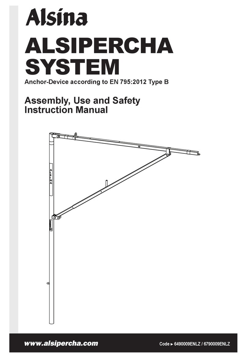
Alsina ALSIPERCHA User manual

ALSIPERCHA
SYSTEM
Assembly, Use and Safety
Instruction Manual
Code ►6490009ENLZ / 6790009ENLZ
Anchor-Device according to EN 795:2012 Type B

6490009ENLZ / 6790009ENLZ ►2◄
Introduction / Certifi cation Alsipercha System
Apart from the assembly and operating instructions, each chapter
includes a series of safety recommendations. It is important that
these are observed. However, these recommendations are neither
exhaustive nor defi nitive, and should they not coincide with the
indications in the Health and Safety Plan or its equivalent according to
local legislation, the latter shall prevail.
If there are persons who cannot read the documentation or have
diffi culty doing so, they must follow the customer’s instructions and
indications.
Should you have any questions regarding the contents of this manual
or any suggestions as to how it can be improved, please address your
comments to your Alsina Marketing Technician or through our website:
www.alsina.com
Info In order to obtain the best performance from its
formwork systems, Alsina continuously updates the
assembly and operation instructions for its products.
For further information, contact the Alsina Marketing
Technician in your area. The locations of the Alsina Group’s
Sales Network are available at www.alsina.com, or you can
Introduction
Alsina’s instructions for installation, use and safety are intended as
a guide to the procedures required for safe and correct assembly,
disassembly and use of formwork systems under normal conditions, in
line with the standards commonly accepted on work sites. Any specifi c
work circumstance falling outside these standards may require them
to be adapted. When in doubt, do not hesitate to contact one of our
technical departments, anywhere in the world.
The instructions in this document are intended to explain to users
and technicians how the system works; they should ensure correct
preparation and use of the equipment on site. Consequently,
there will be references to general standards that any professional
user should be familiar with. Thus, it is best not to reproduce them in
this manual, since any modifi cations to these standards would lead
to discrepancies between the standards and the manual and could
cause confusion. Users should always refer to the latest version of the
standards in force.
Therefore, the references in this manual in no way annul, replace or
prevail over:
1- Standards and regulations on prevention of risks in the workplace
specifi c to a country or region.
2- The instructions in the specifi c Health and Safety Plan for the works.
3- Safety instructions in the evaluations and plans applying to specifi c
work functions in a company.
4- Technical orders and instructions specifi c to particular stages of
the works, issued by the technical directors, the health and safety
offi cer, the foremen and/or Prevention Resources.
Throughout the project, users shall respect, at all times, the specifi c
laws, standards and regulations of the country or region related to
prevention of risks in the workplace and any other legislation applicable
to each case and, if necessary, supplement the instructions and adapt
to other Work Safety Measures.
It is the customer’s responsibility to prepare, document, implement
and review the risk evaluation for the construction work.
This documentation provides the basis for the evaluation of specifi c
risks in the works, and Alsina’s Instruction Manuals may in no case be
regarded as a substitute.
Sets of vertical formwork equipment, as systems, are made up
by joining different components. As far as possible, drawings and
diagrams have been included as an aid to understanding these
instructions. All personnel working with these products should be
familiar with the contents of this document and the safety instructions
therein.
The illustrations in this manual refer, in part, to different phases of the
assembly process. Customers should ensure that they have a copy of
the assembly and operating instructions, supplied by Alsina, and that
these are known to and available to users on site.

6490009ENLZ / 6790009ENLZ ►3◄
Introduction / Certifi cation Alsipercha SystemAlsipercha System
Symbols used in this document:
Information
Information on a section of the assembly and use instructions, or
additional information on the system that users and works technicians
should take into account.
Warning/Precaution/Danger
Essential information that the reader must be aware of; disregarding
this information may lead to material damages or serious personal
injuries.
Advice
Indicates recommendations and advice for use, assembly, and safety.
ISO 9001:2015 Certifi cation
The Alsina Group is ISO 9001:2015 certifi ed.
The Alsina Group has been granted the ISO 9001:2015 certifi cation
for their sales and rental service of concrete formwork equipment.
The certifi cate was granted by BVQI, an institution of renowned
prestige and worldwide experience, under UKAS accreditation.
The scope of this certifi cation confi rms the maturity and effi ciency
of our Quality Management System for the design, manufacture,
marketing (sales and rental) and maintenance of concrete
formwork equipment, provision of scaffolding erection services and
implementation of collective protection systems, while ratifying the
company's commitment to continuous improvement.
Alsina is possibly the only company in the formwork business
with the ISO 9001:2015 certifi cation for: “Design, fabrication,
engineering services, and commercialization (sale and leasing) of
concrete formwork equipment. Provision of assembly services for
scaffolding and formwork equipment. On-site implementation of
collective protection elements”.

Description of the system Alsipercha System
1
23
4
5
6490009ENLZ / 6790009ENLZ ►4◄
Alsipercha (Alsina Fall Arrest System)
Safety system designed to prevent falls from a height during the
formwork boarding process.
Alsipercha
A safety system, especially useful for PERIMETERS, or during all
work associated with decking for horizontal formwork operations.
The system ensures completely safe conditions while installing:
boards, safety handrails, gallows-type safety nets, formwork risers
and all activities involved in formwork assembly where there is risk of
falling from a height.
Easy to assemble and use, does not require outside installers.
Features of the system
- Allows the worker to work safely covering an area of 125 m2 and
moving within a radius of 6.5 m around the column.
- Inverted “L” shaped steel structure measuring 2.5 m long and
4.3 m high (3.5 m when attached to the column).
- Metal structure weighing 80 Kg, made of high quality steel (elastic
limit 42 - 46 Kg/mm2; breaking strength 61 - 76 Kg/mm2).
- Retractable fall arrest block measuring 4m (SRL+lanyard)
maximum length, or optional with SRL 6.0 m or 6.5 m maximum
length.
- Alsipercha housing steel tube measuring 85 cm long.
- To be moved by crane.
- With a wide range of accessories for use in any building site
situation, ensuring safety at all times.
- A system designed for column heights up to 8.5 m (this requires
use of the hook accessory).
- A built-in energy-absorber device reduces the impact forces
transmitted to the structure and to the user.
Info
. The system and its components must be used by
competent, qualifi ed personnel.
Info
. The system and its accessories must be inspected by
competent, qualifi ed personnel:
- Before fi rst use and subsequent use.
- After the system is activated by a fall.
- At regular intervals (at least once a year). The inspection
records may be called for. Certain individual components
may require inspection at shorter intervals.
- Never use the equipment if wear, rust or unauthorized
repair attempts are detected in any part of the system.
- Do not use the system for any use other than that which it
was designed for.
- Use approved harnesses only.
- Do not use or fasten any components or accessories that
have not been supplied by the manufacturer.
- The user must assess the risk involved before using the
system
Limitations of the system
- The structure on which the system is mounted must be capable of
bearing the weights indicated.
- The maximum working radius when the worker is anchored to the
system with the safety harness is 6.5 m. Do not attempt to extend
this working radius with ropes or other such methods.
Info
. The illustrations in this assembly and safety manual
are guidelines and, at any event, they may not refl ect all the
possible assembly formats.
System components
The Alsipercha system is a safety system for preventing falls at
height, designed with different confi gurations.
LEGEND
1. System body
2. SRL
3. Hook
4. Sling
5. Built-in energy-asborber
Alsipercha is CE certifi ed in accordance with the DIN EN 795 type B
(Notifi ed Body 0158, DEKRA EXAM)
LEGEND
1. Manufacturer
2. Name of the product
3. Identifi cation number of the notifi ed
body; DEKRA EXAM GmbH
4. Compliance standard
5. Pictogram: read user
instruction before use
6. Number of users allowed
7. Production year
8. Serial number
2
3
4
5
6
7
8
1

Alsipercha with tripod Alsipercha System
6490009ENLZ / 6790009ENLZ
►5◄
Alsipercha Tripod
Alsipercha Tripod assembly procedure
The ALSIPERCHA TRIPOD, together with Alsipercha, is a solution
that allows workers to safely load/unload trucks from a trailer.
Designed and certifi ed according to the EN 795 anchor devices standard.
The ALSIPERCHA TRIPOD is folded up when it is delivered onsite.
Once it has been placed in its work position, it is assembled according
to the following steps:
2500 mm
2344 mm
2260 mm
1356 mm
2712 mm
3 x 20
10kN
2000 mm
5500 mm
2500 mm
2344 mm
2260 mm
1356 mm
2712 mm
3 x 20
10kN
3000 mm
6500 mm
Component Description
ALSIPERCHA BODY
Description: Inverted “L” shaped unit, to
combine with the tripod.
code dimensions (mm) weight (kg)
84411 2,500 x 4,300 80
SLING
Description: An essential component used to
move the assembly with a crane, or remove it
once the work is complete.
code dimensions (mm) weight (kg)
84414 3,000 0.62
HOOK
Description: Component used to bring the
Alsipercha fall arrest system closer to the
worker when changing the anchorage.
code dimensions (mm) weight (kg)
83418 140 x 2,850 2
RETRACTABLE DEVICE 10M
Description: Retractable component that locks
on a sudden acceleration.
code dimensions (mm) weight (kg)
8441205 10,000 7
HARNESS
Description: Device anchoring the worker to the
Alsipercha fall arrest system.
code dimensions (mm) weight (kg)
84415 500 x 150 1
Info
. In all codes the second digit can be either 3, 4, or 7.
LEGEND
1. System body
2. Diagonal
Energy
Absorber
3. Tripod
LEGEND
1. System body
2. Diagonal
Energy
Absorber
3. Tripod
3
3
2
2
1

Alsipercha with tripod Alsipercha System
6490009ENLZ / 6790009ENLZ
►6◄
TRIPOD
Description: Element that supports and
stabilizes the Alsipercha.
code dimensions (mm) weight (kg)
84475 2,000 90
84478 3,000 98
FH FISCHER ANCHORS Ø18 M12X138.
Description:
code dimensions (mm) weight (kg)
83479 18 x 80 x 25 S 0.01
Step 1
To open the tripod leg, release the connecting PINS.
Step 2
Once the pin has been released, the fi rst foot will open.
Alsipercha tripod mounting procedure
Info
. It is very important to mount the ALSIPERCHA
TRIPOD on suffi ciently compact and resistant terrain so
that the anchor device provides suffi cient safety guarantees.
There are various terrain / slab / footing options:
Option of anchoring to concrete/slab footing
- Minimum characteristics of a concrete platform to anchor the
tripod must be: HA25 concrete or higher (minimum resistance of
concrete for use = 10 MPa, if fresh concrete is used), measurements
of 300 x 300 cm and thickness of 25 cm, as well as a scrap
metal covering.
In this case, the anchor will consist of placing 3 “M12 FISCHER FH
18X80/25 S HIGH RESISTANCE ANCHORS” (or equivalent).
3000 mm
250 mm
40 mm
3000 mm
Option of anchoring to steel plate
- Minimum characteristics of a steel platform to anchor the tripod must
be: measurements of 300 x 300 cm and 4 cm thickness, with three
M18 previously-bored threaded holes through which the anchors will
pass (in this case it will be an 8.8 quality M18x50 DIN933 galvanised
screw with an M18 DIN 125-A washer).

Alsipercha with tripod Alsipercha System
6490009ENLZ / 6790009ENLZ
►7◄
Step 4
ALSINA TRIPOD with one foot open.
Step 5
Turn the TRIPOD 180 degrees, open the second foot, and place it
upright. Use an anchoring element to secure the tripod to a high,
fi xed point so the structure does not overturn. Proceed to open the
third foot.
Step 6
ALSINA TRIPOD in the working position.
Step 7
On the HA25 concrete sole plate, drill with an 18 mm - diameter bit to
a depth of 140 mm.
Step 8
The M12 FISCHER FH 18X80/25 S HIGH RESISTANCE ANCHOR
is fi tted.
Step 3
Secure it in the open position by placing the pin in the R position.

Alsipercha with tripod Alsipercha System
70
100 80 60
60 50
6490009ENLZ / 6790009ENLZ
►8◄
Procedure for use on site
General Information
There are 5.5 or 6.5 metres from the anchor point to the fl oor,
depending on the type of tripod selected, meaning that the worker
can work above the truck load in complete safety. The diameter of the
circular surface occupied by the tripod base is 2.7 m
Safety information
The Alsipercha is only for the operations indicated in this document,
to prevent them from falling when loading on or unloading from delivery
vehicle platforms.
Other spare parts that are not supplied with the system must
not be used.
Check all the parts of the Alsina unloading system components before
installing. Never use the equipment if it is damaged or rusty, as this
may affect its safety.
If activated due to a fall of a user, the retractable device must be
withdrawn from service and inspected by an appropriate person.
If you have any queries, please contact Alsina
Step 9
With a dynamometric wrench, torque to 80 Nm. Repeat for all three
anchors. Finally, using the crane, place the Alsipercha on top of the
ALSIPERCHA TRIPOD.
2,712 mm

Alsipercha with tripod Alsipercha System
100 mm
4
1
2
3
6490009ENLZ / 6790009ENLZ
►9◄
Final assembly
Trucks that are 6 m long
To unload the 6-metre platform of a truck, only one Alsipercha system
will need to be used. When parking the truck, the rear box/platform
must be situated according to the distances shown in the following
illustration:
LEGEND
1. Alsipercha unloading system
2. Alsipercha System
3. 10 m retractable device
4. Worker
Any worker unloading a truck with a 6 m platform, must use:
• Suitable footwear
• A refl ective jacket and a helmet with chin protection
• A safety harness
• 0.3 m additional extension rope for subsequent anchoring
Once the worker has the PPE correct (Personal Protection Equipment),
he can hang the additional 0.3 m rope on his harness by rolling it up
and attach the other end of the fall arrest device to the retractable
element with a snap hook.
The worker must be connected to the system before accessing the
platform.
3000 mm 3000 mm
2400 mm

Alsipercha with tripod Alsipercha System
1
2
3
2
1
3
4
3100 mm 6000 mm 3100 mm
2400 mm
100 mm
4800 mm
6490009ENLZ / 6790009ENLZ
►10◄
Trucks that are 12 m long
As the image below shows, when a 12-metre truck is loaded and
unloaded, two Alsipercha systems must be used simultaneously.
When parking the truck, the rear box/platform must be situated
according to the distances shown in the illustration below.
The worker must be attached to two Alsipercha systems. This will help
him control the movement on the 12 m long platform in the event of
a fall.
If it should be necessary to access the outer corners of the platform, it
is best to move the truck to ensure that the worker is within a range of
3.5 m from the structure.
LEGEND
1. Alsipercha unloading system
2. Alsipercha System
3. 10 m retractable device
4. Worker
Any worker unloading a truck with 12 m platform, must use:
• suitable footwear
• a refl ective jacket and a helmet with chin protection
• a safety harness
• 0.3 m additional extension rope for subsequent anchoring
Once the worker has the correct PPE (Personal Protection Equipment)
he can hang the additional 0.3 m rope on his harness by rolling it up
and attach the other end of the fall arrest device to the retractable
element with a snap hook.
The worker must be connected to the two systems before accessing
the platform.

6490009ENLZ / 6790009ENLZ
►11◄
Employment and Loading of the System Alsipercha System
Report by the Universidad Politécnica de Valencia
(UPV)*
(.../...)
4.- CONCLUSIONS
- This study analyzes the infl uence exerted on the behavior of the
reinforced concrete columns by the use of the Fall Arrest System
developed by ENCOFRADOS J. Alsina, S.A.
(.../...)
The most important conclusions are as follow:
1.- Although the sizes of concrete column sections are usually
selected for shear stress and fl exocompression separately,
this study has considered these jointly, in a similar way to the
analysis of metal structural sections. This makes it easier to
consider the infl uence of the steel tube.
2.- As a result, we estimate that the reduction of section shear
stress resistance caused by the hole in the concrete would
be absorbed assuming, in the fl exocompression calculation,
that the steel of the tube experiences a reduction in elastic
limit which has been taken as 5%, to be on the safe side.
3.- Considering this reduction in the elastic limit of the steel,
the Axis-Moment interaction diagrams for the section were
calculated without modifi cation and including the tube
(for different types of steel and thicknesses of tube).
Accordingly we have determined, for each type of concrete and
steel, the tube thicknesses that cause the interaction diagram
for the modifi ed section to wrap around the original section.
This ensures that there is no loss of resistance for the section for
that thickness of tube.
Report by the Association of Building Consultants
(ACE)*
1. BACKGROUND AND PURPOSE OF THE REPORT
…the checks to assess the structural impact of this system, which is
the subject of this report, will be carried out in accordance with the
following regulations:
-EUROCODE 2: Design of concrete structures. Part 1-1: General rules
and rules for buildings. UNE-EN 1992-1-1:2013
-EUROCODE 3: Design of steel structures. Part 1-1: General rules
and rules for buildings. UNE-EN 1993-1-1:2008
…
5. SUMMARY AND CONCLUSIONS
In the case of a C25/30 concrete column, placing an S-235JR tube
of the dimensions specifi ed in point 2 of this report inside it does not
imply any reduction of its resistant characteristics, as demonstrated in
the previous point.
As a summary, and for different concrete and steel resistances, two tables
(compression and shear) are shown with all possible combinations:
COMPRESSION SHEAR STRESS
Steel Steel
Concrete S235 JR S235 JR S355 JR Concrete S235 JR S235 JR S355 JR
C25/30 1.302 1.524 1.968 C25/30 1.892 2.214 2.858
C30/37 1.085 1.270 1.640 C30/37 1.615 1.890 2.440
C35/45 0.930 1.089 1.405 C35/45 1.411 1.651 2.131
C40/50 0.814 0.953 1.230 C40/50 1.253 1.466 1.893
C45/55 0.724 0.847 1.093 C45/55 1.128 1.320 1.703
C50/60 0.651 0.762 0.984 C50/60 1.025 1.200 1.549
It is observed, for example, that for a steel S-235JR such as that
of the current tube, in concrete with a characteristic strength equal
to or greater than 35 MPa, the safety coeffi cient is lower than the
unit. Therefore, in this case and in all those that appear in red in the
compression table, the incorporated tube as part of the ALSIPERCHA
system supposes a decrease in the resistance capacity of the column.
In these cases, once the formwork has been placed and the system
is no longer used, the hole should be cleaned and then fi lled with a
GROUT mortar of the same resistant characteristics as the concrete
of the column.
We present, for all relevant purposes and based on our fi rm knowledge
and understanding, our opinion which we defer to any other better-
founded opinion, in Girona, on July 11, 2019.
Info
*The original document consists of 8 pages, and is
available to our customers for inspection.
Signed: Pedro A. Calderón García
Dr. Civil Engineering, C. and P.
Head Teacher in Building
and Prefabrication
Signed: Juan Navarro Gregori
Civil Engineering, C. and P.
Assistant Teacher in Concrete
Info
*The original document consists of 17 pages, and is
available to our customers for inspection.

6490009ENLZ / 6790009ENLZ
►12◄
General usage considerations Alsipercha System
General usage considerations
These considerations complement those described in the system’s
assembly and disassembly process.
The system has been designed and calculated for the specifi c uses
and applications described in this manual. Therefore, Alsina accepts
no responsibility for the use of the equipment in situations other than
those described in this manual.
The Alsina Group does not participate in the management or execution
of the project, and the client is solely responsible for the proper use of
the materials supplied.
All the components have suffi cient strength and stability to support
the loads and stresses described in these instructions. It is essential
to place all the system’s components with all the accessories mounted
and properly assembled.
The technical operating instructions, safety indications and data on
loading conditions must be scrupulously observed and followed.
Failure to respect these indications may lead to accidents and severe
injuries (or death) and to considerable material damage.
Systems should not be mixed as they may be incompatible and are
neither designed for nor adapted to the assembly. Alsina rejects all
liability if the system components are replaced with similar components
supplied by another company.
Before starting assembly, the person in charge must plan for loading
and unloading, material storage, and laying out and marking the
areas where the work is to take place, in accordance with the general
organization of the construction work.
The following PPE must be used in the assembly/disassembly:
Gloves, boots, goggles, helmet, refl ective vest, etc.
For heights greater than 3.5 m, a safety harness must be used.
The equipment must be assembled by specialized personnel.
Work areas must be kept clean and orderly.
The largest possible number of operations must be carried out on the
fl oor.
Formwork must be interrupted in the event of heavy rain, snow,
lightning storms, or winds over 65 km/h (service wind pressure of
0.2 kN/m²), removing any materials or tools that may be loose.
Sources of fi re are not allowed near the formwork area.
Workers must always access the work area through the areas made
available for this purpose.
Storage
Having an area designated for compiling and controlling all the
elements supplied is recommended.
Areas must be delimited for the storage of materials or accessory
items for formwork, assembly, use and disassembly of formwork
elements. Personnel not involved in assembly or disassembly shall
not be allowed inside these delimited areas.
Storage shall be properly organized in suitable locations, away from
passageways.
All material must be properly stacked, without exceeding safe heights,
to avoid the risk of toppling or causing diffi culties when roping it for
lifting or transport. Work materials and tools must be placed or stored
so that they cannot collapse, fall or turn over.
Materials stored must be stable, arranged horizontally and wedged
in place.
Materials must not be stored on insecure slopes, unstable or loose
ground, or loose or unstable elements.
If the material is strapped, the straps should not be removed while
there are workers in its path.
Transporting Materials
There must be proper coordination between the crane worker and the
worker who hooks or guides the load. The crane worker must have a
clear view of the trajectory of the load or, failing this, must be assisted
by a guide, communicating with each other using a pre-agreed set of
signals.
Before starting load hoisting, the worker must move away from the
sweep area of the load. When the load is moving, no worker shall
be on it, and movements above or near people should be avoided.
The presence or passage of people under suspended loads must be
avoided.
The load must be well balanced and must be raised and lowered
slowly, avoiding abrupt acceleration and deceleration.
Loads must be lifted vertically, never diagonally, avoiding rocking and
horizontal dragging movements. When necessary, guide ropes or
cables adequate for the load being supported must be used for this
purpose.
When lifting heavy or bulky loads, the use of rocker arms is
recommended.
If the loads could collide with the structure, other on-site elements or
personnel, retention or load-guiding cables should be used.

6490009ENLZ / 6790009ENLZ
►13◄
General usage considerations Alsipercha System
To prevent objects falling onto people and/or materials during hoisting,
loading or unloading operations, using trays or transport containers,
always following the manufacturer's instructions, is recommended.
Alsina provides the ALSINA CONTAINER item. Alternatively, they can
be lifted using slings, distribution beams, rocker arms, etc. in packages
strapped at both ends, hanging the load, thus avoiding horizontal
displacement of the stable assembly. Lifting systems must be with
closed hooks. The crane worker, who will have received the proper
training, shall always be responsible for fi nal review of the attachment
of the load.
Stacking the ALSINA CONTAINER more than three high is not
recommended. They must be stacked on a stable, fl at area.
Simultaneous movements shall not be carried out with the crane.
Loads must be hoisted using mechanical equipment, with a load
capacity suffi cient for the load being lifted.
Equipment Maintenance
A pre-established expiration date cannot be established for formwork,
but improper use of equipment that could cause damage to it must be
avoided.
Alsina, S.A. supplies the formwork material and is responsible for
delivering the equipment in good working condition, in accordance
with the criteria in our quality manual. When assembly is not carried
out by Alsina, the user must accept responsibility for proper use and
maintenance of the equipment.
The users are always responsible for maintaining all equipment,
whether rented or the customer's own property.
When assembling, the material must always be checked by a qualifi ed
individual who will verify that the equipment is apt for use or reject it,
especially in the event of a person falling. There are specifi c control
guidelines for using the main components of the system on site.
These are detailed in the appendix at the end of this section
(Appendix 1). In accordance with these criteria, when a part that is not
fi t for use is identifi ed, it must be rejected, avoiding the use of defective
or damaged parts.
The condition of the material must be checked before the start of a day
after strong winds, rains, snow, etc. since it is possible that a part could
have been dropped, displaced, loosened or damaged.
Annex: Regulationsin Spain
Spanish legislation requires that assembly and dismantling of the
system must be performed by personnel duly trained, as described
in Law 31/1995 and the modifi cations to this law contained in Law
54/2003, for work of this type, and must have the information and tools
required for the proper performance of the task.
Also, the contents of Royal Decree 1627/1997, on minimum health
and safety provisions applicable to construction work, as well as in
Royal Decree 2177/2004, which modifi es Royal Decree 1215/1997,
which establishes the Minimum Health and Safety Provisions for Use
of Work Equipment by Workers, on the subject of temporary work at
heights.
Regulations also require mandatory use of personal protective
equipment adequate for the work to be performed, as described in
Law 31/1995 and its further development in Royal Decree 773/1997.
In cases where workers from multiple companies are active
concurrently, there must be coordination on the subject of prevention,
as defi ned in article 24 of Law 31/1995 and its further development in
Royal Decree 171/2004.

6490009ENLZ / 6790009ENLZ
►14◄
Conditions of use on site Alsipercha System
Alsipercha Body Review Procedure - 84411, column clamps - 83424,
column clamp sleeve - 83426 and Tripod for unlading trucks - 84475,
83472, 84478, 83473 inspection procedure.
Control guidelines Procedure
Place the Alsipercha system on two
trestles and open it up to:
- Check that the bolts, pins, and nuts of the
various extensions are in good condition
and that they can move freely.
- Check that the extensions are neither
askew nor misshapen (maximum
tolerance in both directions is 5 mm).
Pay special attention to ensuring that the
diagonal tube with spring is straight.
- Clean the concrete and particularly some
areas between the two lugs, as this is the
area where various hanger accessories
are housed. If these are closed, open
them with a hammer, until the beam can
enter.
- Inspect the welds, especially on the ring
to which the hood is attached.
If problems are
identifi ed with any
of the above,
contact the Alsina
Service Department.
Warning - Never remove the Alsipercha Body’s diago-
nal tube. Handling the tube may be dangerous. If any
problem is observed in this diagonal, contact the Alsina
Commercial Technician.
Hook Review Procedure - 83418
Control guidelines Procedure
- Check that the hook is neither askew nor
misshapen.
If the deformation is
minor, it can be fi xed
provided that the
tube structure is not
misshapen.
- Clean the concrete.
- Check that there are no fractures.
Appendix 1: Conditions of use on site
Below are the guidelines for reviewing each component of the Alsina
Alsipercha FallArrest System. Reviews should be performed regularly,
once per year at the very least.
As explained in Alsina's Alsipercha Assembly and Safety Manual,
this review does not replace the visual inspection that the user should
perform each time he or she uses the Fall Arrest System.
Retractable Review Procedure - 8441201 / 84439
Control guidelines Procedure
Check that the belt
winds automatically
and unwinds normally along its whole
length.
If it does not work,
remove from service
since it is faulty
.
Check that the locking function is, by
pulling the belt sharply and observing that
it locks.
If it does not work,
remove from service
since it is faulty
.
That the textile is in perfect condition,
without tears or loose ends.
If it does not work,
remove from service
since it is faulty
.
That the metallic parts
are not oxidised
and that the karabiners work and
block
correctly
.
It is important to check that the continuous
energy absorber protected by the plastic
and the fi bres
forming it, have not
broken
.
If it does not work,
remove from service
since it is faulty
.

6490009ENLZ / 6790009ENLZ
►15◄
Conditions of use on site Alsipercha System
Leveller Review Procedure - 83416
Control guidelines Procedure
- Check that the leveller is in its original
condition. Verify that it enters and exits
a housing tube that is in good condition.
- Check that there is no washer.
Verify the level. Check that the leveller
is not broken.
If problems are
identifi ed with any of
the above, contact
the Alsina Service
Department.
Textile Components review procedure: Sling - 84414, Harness - 84415,
HARNESS EXTENSION with Jacket - 84423 / 84474
Control guidelines Procedure
- Check that all textile elements are
present. Check that there are no tears
(especially along the edges) or loose
threads.
- The textile material must be kept in a
clean, dry place.
Otherwise reject

6490009ENLZ / 6790009ENLZ
►16◄
Inspection and maintenance Alsipercha system
A DEVICE IDENTIFICATION SHEET
(A) Distributor / Reseller / Details
(B) Manufacturer
Encofrados J. Alsina S.A.
Pol. Ind. Pla d’en Coll
Camí de la Font Freda, 1
08110 - Montcada i Reixac (Barcelona - Spain)
(C) Product (type, model, code)
(D) User (company, name and address)
(E) Serial number / batch
(F) Year of manufacturer
(G) Purchase date
(H) Date of fi rst use
(M) Notifi ed Body that performed the CE certifi cation / check
DEKRA EXAM GmbH
Dinnendahlstrasse 9 - D-44809 BOCHUM
Phone : +49 (0) 234 3696 105
Website : www.dekra-exam.de
B DEVICE PERIODIC CHECK SHEET
No. (O) Date (P) Reason for check (Q) Name and signature of the per-
son responsible for checking
(R) Notes (defects found or
other relevant information) (S) Check results
(T) Date
of next
check
1□Periodic check
□ Additional check
□ Device fi t for use
□ Device unfi t for use
□ Device to be checked
2□Periodic check
□ Additional check
□ Device fi t for use
□ Device unfi t for use
□ Device to be checked
3□Periodic check
□ Additional check
□ Device fi t for use
□ Device unfi t for use
□ Device to be checked
4□Periodic check
□ Additional check
□ Device fi t for use
□ Device unfi t for use
□ Device to be checked
5□Periodic check
□ Additional check
□ Device fi t for use
□ Device unfi t for use
□ Device to be checked
6□Periodic check
□ Additional check
□ Device fi t for use
□ Device unfi t for use
□ Device to be checked
7□Periodic check
□ Additional check
□ Device fi t for use
□ Device unfi t for use
□ Device to be checked
8□Periodic check
□ Additional check
□ Device fi t for use
□ Device unfi t for use
□ Device to be checked
9□Periodic check
□ Additional check
□ Device fi t for use
□ Device unfi t for use
□ Device to be checked
10 □Periodic check
□ Additional check
□ Device fi t for use
□ Device unfi t for use
□ Device to be checked
Other manuals for ALSIPERCHA
1
Table of contents
Other Alsina Safety Equipment manuals
Popular Safety Equipment manuals by other brands

Climbing Technology
Climbing Technology CROCODILE manual

Vokkero
Vokkero GUARDIAN EUROPE ATEX user guide

DeVilbiss
DeVilbiss MPV-616 Operation manual

Innotech
Innotech VERT-SET-50 Safety instructions and instruction manual

Omron
Omron Sti F3SJ-B P25-01TS Series Quick installation manual

VERTIMA
VERTIMA railoc Assembly and maintenance instructions

3M
3M DBI SALA EXOFIT STRATA 1112475 User instructions

VEVOR
VEVOR Q-3A user manual

CRESTO
CRESTO WORK POSITIONING LANYARD Instructions for use

Petzl
Petzl RAY 11 mm manual

Innotech
Innotech SDH-32 Safety instructions and instruction manual

Nora Lighting
Nora Lighting NX-605 Installation & operation instructions