170B WINDSCREEN .. .The 170B windscreen has been developed for the M-20 and M-30 Altec microphone systems and is extremely
effective in wind noise reduction and "Pop" elimination. The 170B windscreen will attenuate wind noise approximately 24 db
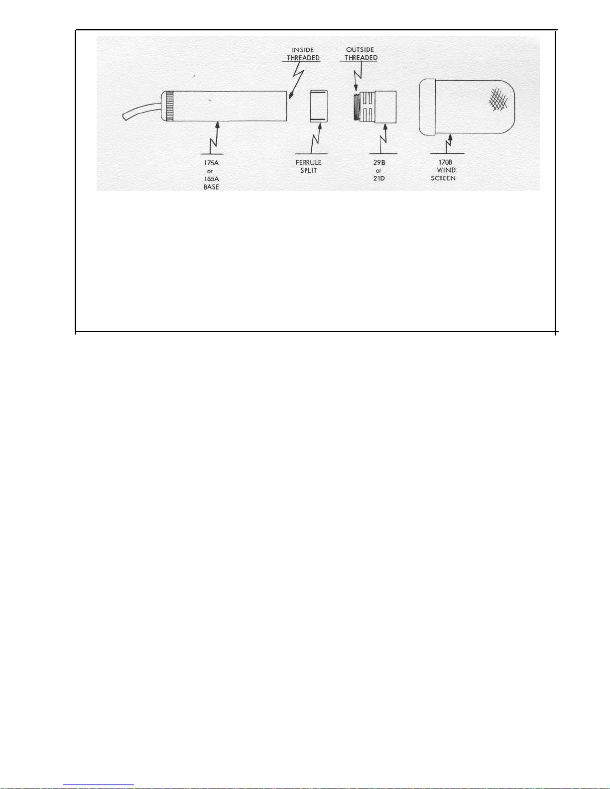
without deteriorating the HF response, or discrimination in the case of the AA-30 usage. An exploded view, Fig. 1, is shown to aid
in the installation of the 170B windscreen. Remove the condenser microphone from its base by unscrewing it counter-clockwise.
Caution: The microphone unit 29B or 21D is a precision element and extreme care should be exercised
in handling. Under no circumstances permit anything to touch the contact end of the microphone
— the end unscrewed from the base — as this could result in damage to the microphone unit.
Slip the split ferrule over the base with the split end toward the cord on the base. Replace the condenser microphone in the
base, inside the ferrule. The windscreen may now be slid over the condenser microphone and onto the ferrule until it 'bottoms.' It
will be noted that the ferrule is split to provide tension on the windscreen and holds it firmly in place regardless of the position of
the microphone and still allows it to be used with any base or stand accessory. If, for any reason, it should be desired to operate
either the M-20 or M-30 Altec microphone system without the 170B windscreen (after it has been installed), it may be removed
without detaching the split ferrule.
The "Pop," or explosive sound produced by most people when pronouncing the letter "P" and sometimes "B" in certain words,
is effectively reduced with the 170B windscreen and therefore greatly increases the ease of close proximity work.
165A Base: The base performs the multiple purpose of mounting the microphone, housing the tube, and enclosing the cable connec-
tions to the tube. The inner structure of this assembly employs a printed circuit phenolic sleeve which supports the tube socket, provid-
ing solder terminating areas for cable wires and tube socket tabs, as well as providing the interconnecting wiring between socket
and cable. The gold plated contact pin at the apex of the assembly is supported by a phenolic bearing cemented into the center
hole of the socket and is connected to the grid by means of the compression spring which surrounds the pin. The cable clamp assem-
bly consists of a special "O" ring, a brass washer, the anodized aluminum clamping nut which completes the case contour, and a
gold plated brass part which supports the printed circuit sleeve and provides threads for mating the outer shell with the clamping
nut. The cable shield and ground wire solder to the brass part and complete the connection to the microphone case through the
outer aluminum shell. The 15' foot length of Tensolite 1883-H6 cable which is part of the base is a six-conductor shielded wire of
small diameter and good flexibility, having an overall jacket of woven fiberglass material providing excellent abrasion resistance.
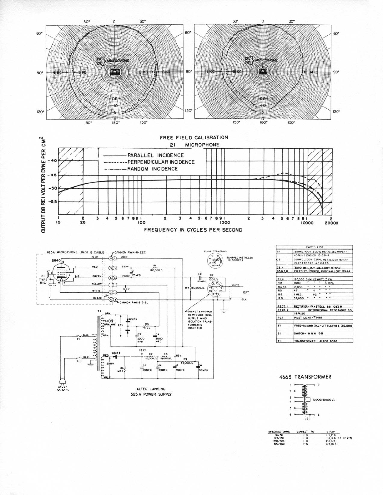
P-525A Power Supply: This unit, by means of a transformer, dry disk rectifiers and filters, supplies direct current potentials for
operation of the 5840 cathode follower tube and condenser microphone in the 165A base. The circuits are conventional and the
location of components are shown in the accompanying photographs. The shorting plug indicated must be removed when the line
balancing transformer is used. When the transformer is inserted in the socket, it will be seen that two holes in the chassis line up
with threaded inserts in the transformer (plug end). It is recommended that the transformer be secured to the chassis using the two
screws furnished.
Service Data: Caution: when removing the cover from the P-525A power supply or the outer shell from the 165A base, disconnect
the power supply from the power line. The metal condenser cans in the power supply are at a positive potential to ground and
require approximately two minutes to lose the charge after the system is disconnected. If the system fails to operate and the pilot
lamp does not glow, check power line connection and fuse located inside of chassis. If system operates but produces loud hum
when the base or microphone is touched, it is an indication of a poor ground connection between the microphone case and the
cable end of the assembly. To correct, tighten microphone and shell.
If the system is inoperative, but the power supply is producing normal heater and B supply voltages, the potential across R4 should
be measured. R4 is the cathode load resistor for the 5840 tube in the 165A base. With the base disconnected from the power
supply, no potential should exist. With the base connected and the microphone button either on or off of the base, the potential
across R4 should be a nominal 200 volts. If this potential is not obtained, the 5840 vacuum tube is faulty or a cable short or open
exists. If the 200 volts is obtained with the microphone button removed from the base, but not when it. is connected; the microphone
backplate has accumulated moisture. This sometimes occurs when the microphone has been stored in atmospheres approaching
100% humidity. The condition will sometimes correct itself in a short time due to the heating effect of the vacuum tube. If not, the
microphone button can be removed from the base and placed in a ventilated 200° F. oven for a period of seven hours. There will
be no harmful effects so long as the temperature does not inadvertently exceed 600° F.
The shell of the 165A base may be easily removed for inspection by holding firmly the knurled cable clamp nut and unscrewing
the upper shell and microphone. It is recommended that the microphone not be removed from the base unless absolutely necessary.
When it is removed, fingers and dirt should be kept away from the back plate surface and the breath, which contains moisture,
should not be used to blow the assembly clean. The 5840 vacuum tube is a premium type designed for dependable performance
under conditions of shock and vibration. Because of its rugged construction, it should provide extreme service life unless subjected
to drastic abuse. It may be removed from its socket by grasping the two sides of the envelope with the fingers, through the open-
ings in the phenolic sleeve, and rocking gently while withdrawing. When free, the tip end should be depressed into the sleeve until
the pins clear the socket allowing it to be tilted out the larger opening in the sleeve. When re-inserting the tube, the same procedure
should be used, entering the tip end of the sleeve first and depressing until the pins clear the opening, allowing alignment with the
socket. When the shell is removed from the base, extreme care should be exercised to protect the spring loaded contact pin at the
apex of the assembly from damage. Before reassembling, the vinyl insulator surrounding the soldered tube socket connections should
be checked, as this is the only insulator between this point and the outer shell. The cable attached to the base may be replaced in
the field, if necessary, the cable clamp is released by holding the upper gold plated brass part by means of a length of 1/8 inch
diameter drill rod entered in the radially located hole and unscrewing the knurled nut using pliers with padded jaws. Connections
to the printed circuit may be soldered using a minimum of heat and preferably using low temperature solder intended for the pur-
pose such as National Lead Co. No. 604-AG. When reassembling the clamp, the 1/8" diameter drill rod serves also as a gauge, the
knurled aluminum nut being tightened until it touches the rod.