Altman AST-9000-UL4-ST2 Series User guide

APPLICATION GUIDE
SMART_TRACK_LIGHTING_APPLICATION_GUIDE_20230329
SMART TRACK LIGHTING
APPLICATION GUIDE

Page 2
Smart Track Lighting Application Guide
Have a question regarding this manual?
Smart Track Lighting Application GuideSmart Track Lighting Application Guide
© Altman Lighting 2023. All rights reserved.
Document Number: 49-027549-0275
Version as of: 2023 March 29th2023 March 29th
The material in this manual is for information purposes only and is subject to change without notice. Altman Lighting assumes no
responsibility for any errors or omissions which may appear in this manual. For comments and suggestions regarding corrections
and/or updates to this manual, please visit the Altman Lighting web site at www.altmanlighting.com or contact your nearest Altman
Lighting Regional Manager.
El contenido de este manual es solamente para información y está sujeto a cambios sin previo aviso. Altman Lighting no asume
responsabilidad por errores o omisiones que puedan aparecer. Cualquier comentario, sugerencia o corrección con respecto a este
manual, favor de dirijirlo a la oficina de Altman Lighting más cercana.
Der Inhalt dieses Handbuches ist nur für Informationszwecke gedacht, Aenderungen sind vorbehalten. Altman Lighting uebernimmt
keine Verantwortung für Fehler oder Irrtuemer, die in diesem Handbuch auftreten. FürBemerkungen und Verbesserungsvorschlaege
oder Vorschlaege in Bezug auf Korrekturen und/oder Aktualisierungen in diesem Handbuch, moechten wir Sie bitten, Kontakt mit der
naechsten Altman Lighting Niederlassung aufzunehmen.
Should you have a suggestion or question regarding your Altman Lighting product, we would love to hear from you.
You can reach us at:
Altman Lighting
1400 East 66th Ave.
Denver, CO. 80229
+1 (303) 500-7072
www.altmanlighting.com
Note: Information contained in this document may not be duplicated in full or in part by any person without prior written approval
of Altman Lighting Its sole purpose is to provide the user with conceptual information on the equipment mentioned. The use of this
document for all other purposes is specifically prohibited.
Altman Lighting continually engages in research related to product improvement. New materials, production methods and design
refinements are introduced into existing products without notice as a routine expression of the philosophy. For this reason any current
Altman Lighting product may differ in some respect from its published description, but will always equal or exceed the original design
specifications unless otherwise noted.
Our Commitment
Preface
The document provides basic information on installation and operational instructions for a quali-
fied, trained installer. These instructions provide information for the following product:
ALTMAN SMART TRACK LIGHTINGALTMAN SMART TRACK LIGHTING
Additional product information can be found on our web site at
www.altmanlighting.com or by scanning the QR code to the right.

Page 3
Smart Track Lighting Application Guide
When using electrical equipment, basic safety precautions should always be followed including the following:
1. READ AND FOLLOW ALL SAFETY INSTRUCTIONS.
2. Do not mount near gas or electric heaters.
3. Equipment should be mounted in locations and at heights where it will not readily be subjected to tampering by
unauthorized personnel.
4. Operate only in approved environments. Do not operate outside unless product is designed to do so.
5. The use of accessory equipment not recommended by the manufacturer may cause an unsafe condition.
6. Do not use this equipment for other than intended use.
7. Refer service to qualified personnel.
SAVE THESE INSTRUCTIONS.
WARNING: You must have access to a main circuit breaker or other power disconnect device before installing
any wiring. Be sure that power is disconnected by removing fuses or turning the main circuit breaker off before
installation. Installing the device with power on may expose you to dangerous voltages and damage the device. A
qualified electrician must perform this installation.
WARNING: Refer to National Electrical Code® and local codes for cable specifications. Failure to use proper
cable can result in damage to equipment or danger to personnel.
WARNING: This equipment is intended for installation in accordance with the National Electric Code® and
local regulations. Before any electrical work is performed, disconnect power at the circuit breaker or remove the fuse
to avoid shock or damage to the control. It is recommended that a qualified electrician perform this installation.
WARNING: This Lighting Fixture IS NOT for residential installation or use.
WARNING: The structure where fixture(s) is to be mounted must be capable of supporting the weight of
the fixture and its accessories. This fixture is for temporary, portable mounting only.
WARNING: The light source contained in this luminaire shall only be replaced by the manufacturer or his
service agent or a similar qualified person.
THIS PRODUCT MUST BE INSTALLED IN ACCORDANCE WITH THE APPLICABLE INSTALLATION CODE
BY A PERSON FAMILIAR WITH THE CONSTRUCTION AND OPERATION OF THE PRODUCT AND THE
HAZARDS INVOLVED.
CE PRODUIT DOIT ÊTRE INSTALLÉ SELON LE CODE D’INSTALLATION PERTINENT, PAR UNE
PERSONNE.
CONSULT A QUALIFIED ELECTRICIAN TO ENSURE CORRECT BRANCH CIRCUIT CONDUCTOR.
CONSULTER UN ÉLECTRICIEN QUALIFIÉ POUR VOUS ASSURER QUE LES CONDUCTEURS DE LA
DÉRIVATION SONT ADÉQUATS.
Product Safety Notices
Warnings
Important Information

Page 4
Smart Track Lighting Application Guide
FCC Notice
This equipment has been tested and found to comply with the limits for a Class A digital device, pursuant to part 15 of the FCC
Rules. These limits are designed to provide reasonable protection against harmful interference when the equipment is operated in a
commercial environment. This equipment generates, uses, and can radiate radio frequency energy and, if not installed and used in
accordance with the instruction manual, may cause harmful interference to radio communications.
Operation of this equipment in a residential area is likely to cause harmful interference in which case the user will be required to cor-
rect the interference at his own expense.
Altman Lighting Product Warranty
Warranty Terms
Altman Lighting, Inc., a subsidiary of Altman Stage Lighting Company, Inc., herein referred to as Altman, warrants each new product
(except for spare parts or products Altman does not manufacture) for a period of TWO (2) years from date of shipment to correct
by repair or replacement any part defect due to faulty material or workmanship. Under these same terms products with an LED light
source shall be warranted for a period of FIVE (5) years and One (1) day.
Altman warrants for NINETY (90) days any spare part it manufactures. On spare parts or products Altman does not manufacture,
including, but not limited to, lamps, sockets, lenses, roundels, electronics, ignitors, ballasts, etc.; Altman will grant the same war-
ranty given Altman by its vendors. Altman assumes no responsibility for damage or faulty performance caused by misuse, improper
installation, careless handling or where repairs have been attempted by others. This warranty is in lieu of all warranties or guarantees
expressed or implied and no representative or person is authorized to assume Altman any other liability with the sale of Altman’s
products.
Altman assumes no responsibility for damage or faulty performance caused by misuse, improper
Installation, careless handling or where repairs have been attempted by others.
This warranty is in lieu of all warranties or guarantees expressed or implied and no representative or person is authorized to assume
Altman any other liability with the sale of Altman’s products.
The customer must receive a Return Material Authorization (RMA) number prior to return, return shipment must be visibly marked
with the RMA number and the product must be returned (shipping prepaid) to the factory at:
1400 East. 66th Avenue
Denver, CO 80229 USA
+1-303-500-7072
The return must be within THIRTY (45) days of receiving the RMA from Altman. Altman warrants for NINETY (90) days any spare
part it manufactures. On spare parts or products Altman does not manufacture, such as lamps, sockets, lenses, roundels, electronics,
ignitors, ballasts, etc. Altman will grant the same warranty given Altman by its vendors.
Warranty Service

Page 5
Smart Track Lighting Application Guide
Table Of Contents
Important Information 3
Product Safety Notices 3
Warnings 3
Altman Lighting Product Warranty 4
Warranty Terms 4
Warranty Service 4
Preface 6
About this Manual 6
About Smart Track Lighting 6
DMX512A/RDM Standards 7
Altman Smart Track Overview 8
Smart Track Standard Lighting Track 8
Smart Track Standard Couplers 8
Smart Track Standard Live End Feeds 8
Smart Track Standard Dead End Cap 8
Electrical Straight Coupler (Data and Power) 8
Smart Track Standard Straight I Coupler 8
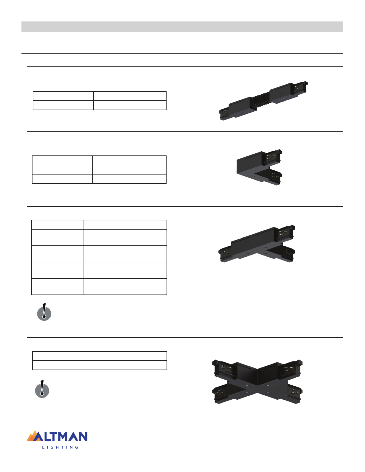
Smart Track Flexible Coupler 9
Smart Track Standard L-Coupler 9
Smart Track Standard T-Coupler 9
Smart Track Standard X-Coupler 9
Smart Track Recessed Lighting Track 10
Smart Track Recessed Couplers 10
Smart Track Recessed Live End Feeds 10
Smart Track Recessed Dead End Cap 10
Smart Track Recessed Straight I Coupler 10
Smart Track Recessed L-Coupler 10
Smart Track Recessed T-Coupler 11
Smart Track Recessed X-Coupler 11
Smart Track Cutting Tool For Track Conductors 11
Smart Track Current Limiting Devices 12
End-Feed With Current Limiting Feeds 12
Middle-Feed With Current Limiting Feeds 12
End-Feed With Small Current Limiting Feeds 12
Smart Track Ceiling Monopoint 12
Smart Track Aircraft Mount Kits 13
Smart Track Pendant Mount Kits 15
Planning and Design 16
General Product Information 16
Smart Track Lighting 2-Circuit Specification 16
Smart Track Luminaire Specification 16
Warning and Notices 17
Track, Components, and DMX Contacts 18
Coupler Examples 19
Examples Of Dmx Termination 19
Examples Of Systems Layout 19
Planning Aid - Track/Components 20
Single Track Straight Run-Feed Left and Right 20
Independent Tracks Sharing DMX Data / AC Feeds 21
3 Straight Runs of Smart Track with “L” Coupler 22
2 Straight Runs of Smart Track with “L” Coupler 22
Straight Runs of Smart Track with Flex Coupler 23
Sample Installation & Guidelines 24
Easy to Cut on Site 24
Smart Track Mounting 24
Pre-Punch Mounting Holes 24
Smart Track Load Distributions 24
Pendant Style Mounting 25
Aircraft Cable Mounting 25
Track-to-Track Connections 25
Power Wiring 26
Live Feed Coupler Installation and Wiring 26
Recessed Cover Installation 27
Monopoint Ceiling Adapter Installation 27
Recessed Monopoint Ceiling Adapter Install 28
Adapter Mounting Into The Track 28
Installing Circuit Limiting Feed Device 29

Page 6
Smart Track Lighting Application Guide
Preface
About this Manual
This document only provides general information for Altman Lighting’s Smart Track Lighting system and products. Refer to the
product’s installation and operation manual for specific product information.
About Smart Track Lighting
Altman Smart Track Lighting Systems are a revolutionary way to bring DMX control and power to addressable architectural / theatrical
luminaires. Smart Track eliminates the need for additional data wiring.
Smart Track Lighting is easy to lay out, install, and offers lighting professionals the opportunity to createand activate new lighting
scenes time after time. Smart Track Lighting is a track based lighting system that carries both power and data down the same track
system. This system allows for simple installation of “smart luminaires” which when connected to the Smart Track can be controlled
via DMX. As with all DMX systems - DMX rules need to be followed for proper fixture control.
The Smart Track Lighting System works in conjunction with numerous Altman luminaires from Incandescent to LED. These fixtures
include but are not limited to the Altman Gallery, IQ Series, UV, LED and Micro series products. Luminaries fitted with smart track
adapters have an addressable DMX dimmer for quartz units and DMX interface for LED color changing and white lighting units. Units
fitted with “Non-Smart” track heads work through direct power and cannot be addressed or controlled via data but can be
controlled if the head end of the track is outfitted with a mains dimmer. Note that the fixtures attached to the track must also be suit-
able for use with a phase cut dimmer.
These unique features and capabilities of Altman Smart Track Lighting System make it the ideal solution for many applications. The
system is suitable for retail stores, museums, churches, restaurants, theme parks, night clubs and much more. Altman Smart Track
Lighting System is a comprehensive system of components that offer innovative solutions for transporting control signals as well as
power to individual luminaires. The heavy duty extruded aluminum track is ideal for demanding applications where a low profile look
is desired and numerous luminaires are required. The Altman Smart Track luminaires retain their identity and programming, even
when moved from location to location along the track.
Smart Track Lighting System is compatible with DMX and many are RDM enabled (Remote Device Management) luminaires. It can
also be integrated into existing systems to transform into new designs. By incorporating the digital control signal into the track, this
system allows dimming and lighting effects to be obtained when using any of the numerous compatible Altman luminaires.

Page 7
Smart Track Lighting Application Guide
DMX512A/RDM Standards
DMX512A (DIGITAL MULTIPLEX) is a standard for digital communication networks that are commonly used to control architectural
and stage lighting. The ANSI standard of E1.11 employs a differential signal at its physical layer in conjunction with a variable size
packet based communication protocol.
The DMX512 standard requirements are:
• Maximum length: 1000 feet
• Wiring type recommended: Belden 9842, 9729,9829, Proplex, Cat5 UTP/STP (Note: A Network is only as good as its Cable)
• Maximum units per bus: 32 (20 RDM devices) - breaking your DMX512 network links and units per data link into smaller seg-
ments is always more desirable
• 120 ohm termination at the end of each run, if a DMX512 network is not terminated, the DMX signal arrives at the far end of the
chain and is “reflected” back up the line to the transmitter, also note that “over terminating” a DMX512 network is just as bad as
this will overload the driver circuit.
All Devices in a DMX512 system must be connected in a “daisy chain” fashion and should never be run ina “WYE/2-fer” fashion.
Utilization of DMX splitters and networked devices is always recommended when long runs or multiple DMX LANs are needed for
One or more DMX networks. DMX splitters Permit a star layout with out breaking the rules. Each output of the splitter is driving a
new DMX512 link on the network. These generally have one (1) DMX input and multiple outputs. Please know that a repeater will be
needed for each DMX universe.
Common Data issues with DMX Networks
• Too many devices on the line (Maximum units per bus: 32 DMX or 20 RDM devices)
• Improper termination on the line.
• DMX can “sometimes work” with the Data - (minus) missing.
• If a DMX splitter “cleans up” an issue check the system for ground loops.
XLR-5 Pin Out
1) Signal Common
2) Data 1- (Primary Data Link)
3) Data 1+ (Primary Data Link)
4) Data 2- (Optional Secondary Data Link)
5) Data 2+ (Optional Secondary Data Link)
RJ-45 Pin Out
1) Data 1+
2) Data 1-
3) Data 2+
4) Not Assigned
5) Not Assigned
6) Data 2-
7) Signal Common (0 V) for Data 1
8) Signal Common (0 V) for Data 2

Page 8
Smart Track Lighting Application Guide
Altman Smart Track Overview
Smart Track Standard Lighting Track
The track is available in black or white powder coat or silver anodized. All system components and adapters are available in white,
black or silver painted finish. Please refer to the specific luminaire’s data sheet for available color choices for your specified Smart
Track Luminaire.
ModelModel DescriptionDescription
AST-9000-UL4-ST2-* 4’ - 2-circuit Smart Track™ - Standard
AST-9000-UL8-ST2-* 8’ - 2-circuit Smart Track™ - Standard
AST-9000-UL12-ST2-* 12’ - 2-circuit Smart Track™ - Standard
Smart Track Standard Couplers
Smart Track Standard Live End FeedsSmart Track Standard Live End Feeds
Live end feeds are utilized in the track system to bring both power and data to the “feed” or beginning of the track. These live feeds
are wired to the input power and data and make contact with the appropriate bus ways in the track to transfer power and data to the
luminaires. With gold plated DMX / data bus contacts and nickel plated line voltage springs for feeding AC and DMX in or out.
ModelModel DescriptionDescription
AST-9001-* Live End, Polarity Right
AST-9002-* Live End, Polarity Left
Electrical Straight Coupler (Data and Power)Electrical Straight Coupler (Data and Power)
Straight coupler for joining two pieces of Smart Track. Can be used as a feed for either DMX / data and AC. Note: DMX / data must
run linear.
ModelModel DescriptionDescription
AST-9003-* Straight Coupler / Jointing
Connector
Smart Track Standard Straight I Coupler (Data and Power)Smart Track Standard Straight I Coupler (Data and Power)
Straight I coupler for joining two pieces of Smart Track. Can be used as a feed for either DMX / data and AC. Note: DMX / data must
run linear.
ModelModel DescriptionDescription
AST-9010-* I-Coupler / Middle Feed
Note: * Add one of the following codes for finish: B - Black, W - White and S - Silver, . Some items are only available in color noted
in their description.
Smart Track Standard Dead End CapSmart Track Standard Dead End Cap
End cap for end of track run.
ModelModel DescriptionDescription
AST-9004-* End Cap for Standard Track
See Page 26 for Installation and wiring of the Live End Feed

Page 9
Smart Track Lighting Application Guide
Smart Track Standard Couplers
Smart Track Flexible CouplerSmart Track Flexible Coupler
The flexible connector can be used from 30° to 330°. Can be used as a DMX/ data & AC feed or as a pass through. Note: DMX/ data
must be run linear.
ModelModel DescriptionDescription
AST-9018-* Flexible Straight Coupler
Smart Track Standard L-CouplerSmart Track Standard L-Coupler
L-Coupler with DMX / data contacts. Can be uses as a feed for either DMX / data or AC. Note: DMX / data must be run linear.
Smart Track L-Coupler.
ModelModel DescriptionDescription
AST-9011-* L-Coupler, Polarity Inside
AST-9012-* L-Coupler, Polarity Outside
Smart Track Standard X-CouplerSmart Track Standard X-Coupler
Four-way, 90° track joiner. Can be used as a DMX / data and AC feed or as a pass through.
Smart Track Standard T-CouplerSmart Track Standard T-Coupler
T-Coupler for joining three track sections. Can be used as a DMX / data and AC feed or as a pass through.
ModelModel DescriptionDescription
AST-9013-* T-Coupler with Polarity Outside
Left / Ground Inside Right
AST-9014-* T-Coupler with Polarity Outside
Right / Ground Inside Left
AST-9015-* T-Coupler with Polarity Inside
Left / Ground Outside Right
AST-9016-* T-Coupler with Polarity Inside
Right / Ground Outside Left
ModelModel DescriptionDescription
AST-9017-* X-Coupler
IMPORTANT!IMPORTANT! Special care must be taken when laying out and wiring DMX / data in and out of the T-Coupler to keep the DMX running linear. This
means breaks inside the T-Coupler on the control signal may be necessary. If more than one DMX/ data line is necessitated for the control wiring layout.
IMPORTANT!IMPORTANT! Special care must be taken when laying out and wiring
DMX / data in and out of the X-Coupler to keep the DMX running
linear. This means breaks inside the X-coupler on the control signal
may be necessary. More than one DMX / data line may need to be run.
Note: * Add one of the following codes for finish: B - Black, W - White and S - Silver, . Some items are only available in color noted in their description.

Page 10
Smart Track Lighting Application Guide
Smart Track Recessed Lighting Track
The track is available in black or white powder coat or silver anodized. All system components and adapters are available in white,
black or silver painted finish. Please refer to the specific luminaire’s data sheet for available color choices for your specified Smart
Track Luminaire.
ModelModel DescriptionDescription
AST-9000-UL4-RE2-* 4’ - 2-circuit Smart Track™ - Recessed
AST-9000-UL8-RE2-* 8’ - 2-circuit Smart Track™ - Recessed
AST-9000-UL12-RE2-* 12’ - 2-circuit Smart Track™ - Recessed
Smart Track Recessed Couplers
Smart Track Recessed Live End FeedsSmart Track Recessed Live End Feeds
Live end feeds are utilized in the track system to bring both power and data to the “feed” or beginning of the track. These live feeds
are wired to the input power and data and make contact with the appropriate bus ways in the track to transfer power and data to the
luminaires. With gold plated DMX / data bus contacts and nickel plated line voltage springs for feeding AC and DMX in or out.
ModelModel DescriptionDescription
AST-9001-RE2-* Live End, Polarity Right
AST-9002-RE2-* Live End, Polarity Left
Smart Track Recessed Straight I Coupler (Data and Power)Smart Track Recessed Straight I Coupler (Data and Power)
Straight I coupler for joining two pieces of Smart Track. Can be used as a feed for either DMX / data and AC. Note: DMX / data must
run linear.
ModelModel DescriptionDescription
AST-9010-RE2-* I-Coupler / Middle Feed
Note: * Add one of the following codes for finish: B - Black, W - White and S - Silver, . Some items are only available in color noted in their description.
Smart Track Recessed Dead End CapSmart Track Recessed Dead End Cap
End cap for end of track run.
ModelModel DescriptionDescription
AST-9004-RE2-* End Cap for Recessed Track
Smart Track Recessed L-CouplerSmart Track Recessed L-Coupler
L-Coupler with DMX / data contacts. Can be uses as a feed for either DMX / data or AC. Note: DMX / data must be run linear.
Smart Track L-Coupler.
ModelModel DescriptionDescription
AST-9011-RE2-* L-Coupler, Polarity Inside
AST-9012-RE2-* L-Coupler, Polarity Outside
AST-9001-RE2-* / AST-9002-RE2-* Includes AST-9001-R-6-* Recessed Cover
AST-9010-RE2-* Includes AST-9010-R-6-* Recessed Cover
AST-9011-RE2-* / AST-9012-RE2-* Includes AST-9011-R-6-* Recessed Cover
See Page 26 for Installation and wiring of the Live End Feed
See Page 27 for Recessed Cover Installation

Page 11
Smart Track Lighting Application Guide
Smart Track Recessed Couplers
Smart Track Recessed X-CouplerSmart Track Recessed X-Coupler
Four-way, 90° track joiner. Can be used as a DMX / data and AC feed or as a pass through.
Smart Track Recessed T-CouplerSmart Track Recessed T-Coupler
T-Coupler for joining three track sections. Can be used as a DMX / data and AC feed or as a pass through.
ModelModel DescriptionDescription
AST-9013-RE2-* T-Coupler with Polarity Outside
Left / Ground Inside Right
AST-9014-RE2-* T-Coupler with Polarity Outside
Right / Ground Inside Left
AST-9015-RE2-* T-Coupler with Polarity Inside
Left / Ground Outside Right
AST-9016-RE2-* T-Coupler with Polarity Inside
Right / Ground Outside Left
ModelModel DescriptionDescription
AST-9017-RE2-* X-Coupler
IMPORTANT!IMPORTANT! Special care must be taken when laying out and wiring DMX / data in and out of the T-Coupler to keep the DMX running linear. This
means breaks inside the T-Coupler on the control signal may be necessary. If more than one DMX/ data line is necessitated for the control wiring layout.
IMPORTANT!IMPORTANT! Special care must be taken when laying out
and wiring DMX / data in and out of the X-Coupler to keep the
DMX running linear. This means breaks inside the X-coupler
on the control signal may be necessary. More than one DMX
/ data line may need to be run.
Note: * Add one of the following codes for finish: B - Black, W - White and S - Silver, . Some items are only available in color noted in their description.
AST-9013-RE2-* / AST-9014-RE2-* / AST-9015-RE2-* / AST-9016-RE2-* /
Includes AST-9013-R-6-* Recessed Cover
AST-9017-RE2-* / Includes AST-9017-R-6-* Recessed Cover
Smart Track Cutting Tool For Track ConductorsSmart Track Cutting Tool For Track Conductors
ModelModel DescriptionDescription
AST-S-9000/T Cutting Tool
ModelModel DescriptionDescription
61-DMXCAT DMXcat for addressing fixtures via RDM (Required for DMX Model)
ST-STU-PDTO AP-150 / Pegasus Track Mounting Kit with and Data/ PowerCon and Fixture Mount
ST-STU-PDTO-PK AIP200 Track Mounting Kit with Seetronic Power and Data with Fixture Mount
ST-STU-PTO AP-150 / Pegasus Track Mounting Kit with PowerCon and Fixture Mount (No Data)
ST-STU-PTO-PK AIP200 Track Mounting Kit with Seetronic Power with Fixture Mount (No Data)
Smart Track Programming Devices and Adapters
See Page 27 for Recessed Cover Installation

Page 12
Smart Track Lighting Application Guide
Smart Track Current Limiting Devices
End-Feed With Current Limiting FeedsEnd-Feed With Current Limiting Feeds
ModelModel DescriptionDescription
AST-9001-CL-* Live End Feed with Circuit Limiting
Feed, Polarity Right
AST-9002-CL-* Live End Feed with Circuit Limiting
Feed, Polarity Left
Middle-Feed With Current Limiting FeedsMiddle-Feed With Current Limiting Feeds
ModelModel DescriptionDescription
AST-9010-CL-* Middle Feed with Circuit Limiting
Feed
End-Feed With Small Current Limiting FeedsEnd-Feed With Small Current Limiting Feeds
ModelModel DescriptionDescription
AST-9001-CL-S-* Live End Feed with Small Circuit
Limiting Feed, Polarity Right
AST-9002-CL-S-* Live End Feed with Small Circuit
Limiting Feed, Polarity Left
Note: End Feeds require at least one circuit breaker and can have a maximum of two. I-Couplers must have two circuit breakers. Circuit breakers for current limiting
products are found at the end of this section.
Smart Track Ceiling Monopoint
Note: * Add one of the following codes for finish: B - Black, W - White and S - Silver, . Some items are only available in color noted in their description.
Note: Circuit Breakers are sold separately
ModelModel DescriptionDescription
AST-9000-BPU-D-* Ceiling Monopoint Adapter with Data
bus
AST-9000-BRU-D-* Ceiling Monopoint Adapter for Base
for Recessed Fixing
Note: The AST-9000-BRU-D-* does not include the Monopoint Adapter
Note: * Add one of the following codes for finish: B - Black, W - White. Some items are only available in color noted in their description.
See Page 29 for Current Limiting Feeds Installation
See Page 27 for Ceiling Monopoint Installation
See Page 28 for Recessed Ceiling Monopoint Installation

Page 13
Smart Track Lighting Application Guide
Smart Track Aircraft Mount Kits
Suspension Kit with Screw Gripper with Steel CableSuspension Kit with Screw Gripper with Steel Cable
ModelModel DescriptionDescription
AST-9000-KIT1-1.5
Suspension Kit with Screw Gripper + Steel Cable
(Diameter 1.5 mm, Length 1.5 m) + Clamp with
Auto Gripper
AST-9000-KIT1-3
Suspension Kit with Screw Gripper + Steel Cable
(Diameter 1.5 mm, Length 3 m) + Clamp with Auto
Gripper
Suspension Kit with Ceiling ClampSuspension Kit with Ceiling Clamp
ModelModel DescriptionDescription
AST-9000-KIT2-1.5-*
Suspension Kit with Ceiling Clamp + Plastic Cup
+ Steel Cable (Diameter 1.5 mm - Length 1.5 m)
with a Spherical End + Fast Fixing Clamp
AST-9000-KIT2-3-*
Suspension Kit with Ceiling Clamp + Plastic Cup
+ Steel Cable (Diameter 1.5 mm - Length 3m)
with a Spherical End + Fast Fixing Clamp..
AST-9000-KIT2-5-*
Suspension Kit with Ceiling Clamp + White Plas-
tic Cup + Steel Cable (Diameter 1.5 mm - Length
5 m) with a Spherical End + Fast Fixing Clamp
Suspension Kit with Screw Gripper-Steel CableSuspension Kit with Screw Gripper-Steel Cable
ModelModel DescriptionDescription
AST-9000-KIT3-1.5-*
Suspension Kit with Screw Gripper + Plastic Cup
+ Steel Cable (Diameter 1.5 mm - Length 1.5 m)
+ Bracket with Automatic Gripper
AST-9000-KIT3-3-*
Suspension Kit with Screw Gripper + Plastic Cup
+ Steel Cable (Diameter 1.5 mm - Length 3m) +
Bracket with Automatic Gripper
AST-9000-KIT3-5-*
Suspension Kit with Screw Gripper + Plastic Cup
+ Steel Cable (Diameter 1.5 mm - Length 5m) +
Bracket with Automatic Gripper
Suspension Kit with Round Head Ceiling AttachmentSuspension Kit with Round Head Ceiling Attachment
ModelModel DescriptionDescription
AST-9000-KIT4-1.5-*
Suspension Kit with Round Head Ceiling Attach-
ment + Steel Cable (Diameter 1.5mm - Length
1.5 m) with a Spherical End + Clamp with
Automatic Gripper
AST-9000-KIT4-5-*
Suspension Kit with Round Head Ceiling Attach-
ment + Steel Cable (Diameter 1.5mm - Length
5m) with a Spherical End +Clamp with Auto-
matic Gripper
Note: * Add one of the following codes for finish: B - Black, W - White. Some items are only available in color noted in their description.

Page 14
Smart Track Lighting Application Guide
Smart Track Aircraft Mount Kits
Suspension Kit with Screw Gripper-Black Plastic Cup-Steel CableSuspension Kit with Screw Gripper-Black Plastic Cup-Steel Cable
ModelModel DescriptionDescription
AST-9000-KIT5-1.5
Suspension Kit with Screw Gripper + Black Plastic
Cup + Steel Cable (Diameter 1.5 mm - Length 1.5
m) with a Spherical End + Short Pendant Bracket for
Suspensions
AST-9000-KIT5-5
Suspension Kit with Screw Gripper + Black Plastic
Cup + Steel Cable (Diameter 1.5 mm - Length 3m)
with a Spherical End + Short Pendant Bracket for
Suspensions
Suspension Kit with Screw Gripper-Black Plastic Cup-Steel CableSuspension Kit with Screw Gripper-Black Plastic Cup-Steel Cable
ModelModel DescriptionDescription
AST-9000-KIT6-1.5-*
Suspension Kit with Screw Gripper + Plastic Cup
+ Steel Cable (Diameter 1.5mm - Length 1.5m) +
Short Pendant Bracket with Countersunk Hole for
Suspensions with Automatic Gripper
AST-9000-KIT6-3-*
Suspension Kit with Screw Gripper + Plastic Cup
+ Steel Cable (Diameter 1.5mm - Length 3m) +
Short Pendant Bracket with Countersunk Hole for
Suspensions with Automatic Gripper
AST-9000-KIT6-5-*
Suspension Kit with Screw Gripper + Plastic Cup
+ Steel Cable (Diameter 1.5mm - Length 5m) +
Short Pendant Bracket with Countersunk Hole for
Suspensions with Automatic Gripper
Suspension Kit with Round Head Ceiling Attachment-Steel CableSuspension Kit with Round Head Ceiling Attachment-Steel Cable
ModelModel DescriptionDescription
AST-9000-KIT8-1.5-*
Suspension Kit with Round Head Ceiling Attach-
ment + Steel Cable (Diameter 1.5 mm - Length 1.5
m) with a Spherical end + Short Pendant Bracket
with Countersunk Hole for Suspensions with
Automatic Gripper
AST-9000-KIT8-3-*
Suspension Kit with Round Head Ceiling Attach-
ment + Steel Cable (Diameter 1.5 mm - Length
3m) with a Spherical end + Short Pendant Bracket
with Countersunk Hole for Suspensions with
Automatic Gripper
AST-9000-KIT8-5-*
Suspension Kit with Round Head Ceiling Attach-
ment + Steel Cable (Diameter 1.5 mm - Length
5m) with a Spherical end + Short Pendant Bracket
with Countersunk Hole for Suspensions with
Automatic Gripper
Note: * Add one of the following codes for finish: B - Black, W - White. Some items are only available in color noted in their description.

Page 15
Smart Track Lighting Application Guide
Smart Track Pendant Mount Kits
Suspension Set Pendant Mount with Metal Cup CanopySuspension Set Pendant Mount with Metal Cup Canopy
ModelModel DescriptionDescription
AST-S-9000-P1-UL-SF-***-* Suspension Set- Crossbar + Metal cup +
Mounting bracket + Stem*
Suspension Set Pendant Mount with Flat CanopySuspension Set Pendant Mount with Flat Canopy
ModelModel DescriptionDescription
AST-S-9000-P2-UL-SF-***-* Suspension Set- Crossbar + Flat Canopy +
Mounting bracket + Stem*
Suspension Set with Power Cord GasketSuspension Set with Power Cord Gasket
ModelModel DescriptionDescription
AST-S-9000-P3-P-UL-****-* Suspension Set - With power cord gasket
(power cord not included)
Note: * Add one of the following codes for finish: B - Black, W - White. Some items
are only available in color noted in their description.
Note: *** - Add one of the following codes for Stem Length: 12 - 12 inches, 24 - 24
inches and 48 - 48 inches
Note: * Add one of the following codes for finish: B - Black, W - White. Some items
are only available in color noted in their description.
Note: *** - Add one of the following codes for Stem Length: 12 - 12 inches, 24 - 24
inches and 48 - 48 inches
Note: * Add one of the following codes for finish: B - Black, W - White. Some items
are only available in color noted in their description.
Note: **** - Add one of the following codes for Cable Length: 36 - 36 inches,
120 - 120 inches and 200 - 200 inches
Note: Cable Gripper and Track Bracket not included

Page 16
Smart Track Lighting Application Guide
Planning and Design
General Product Information
Before you begin planning, this section contains some basic product specification and precautions when planning, designing, and
installing a Smart Track Lighting system.
Smart Track Lighting 2-Circuit SpecificationSmart Track Lighting 2-Circuit Specification
The Track Lighting System shall consist of high quality aluminum extruded lighting track with integral data distribution, rugged multi
adapters to support fixtures & transfer power/ data from the track to controllable devices such as lighting fixtures. It shall be possible
to field cut Track Sections to necessary lengths for each project and location. The top of the track shall have an extruded profile to
allow for the mounting a manufacturer supplied bracket/ hanging supports for connecting with contractor supplied stem, cable or
threaded rod. Track Sections shall distribute two 20 Amp, 120 VAC power circuits with independent neutrals and shall include inte-
gral distribution of DMX-512A (ANSI E.1.11-2004) and RDM (ANSI E1.20- 2006) control signals to lighting fixtures and controllable
devices mounted on the Smart Track.
Connection points shall be available for both wired and wireless connection of controls to the Lighting System. The Lighting System
shall have a complete line of components to join data and electrify separate track pieces, including: Live End Feeds, Dead End Caps, In-
Line Couplers, Feed Thru Connectors, L Turns (left and right), Flexible Couplers, X-Connectors, T-Connectors, and Data Terminators.
All components of the Lighting System shall be UL or ETL listed.
Smart Track Luminaire SpecificationSmart Track Luminaire Specification
Fixtures for use on the DMX track system shall include an on-board DMX interface and an installed Multi-Adapter designed to me-
chanically hang, power and feed data. Fixtures compatible with the Lighting System shall include incandescent, low voltage, CDM, and
LED sources. Luminaires shall be compatible with DMX-512A (ANSI E.1.11-2004) and RDM (ANSI E1.20-2006) control protocols.
LED fixtures shall feature integral power supplies, drivers, pre-programmed modes and DMX interface. Quartz fixtures shall have
an integral, on-board DMX controlled phase-forward (leading edge) dimmer compatible with incandescent, low voltage, and certain
phase-dimmable LED loads. Metal Halide (CDM) fixtures shall have an on-board DMX on/off relay rated for a maximum of 70 Watts.
DMX addressing for all system fixtures shall be conducted via either (a) manual setting of the rotary dials for Dimmer & CDM lu-
minaires (b) push button display for LED or (c) RDM from a remote location by a compatible hand held programmer or personal
computer. Luminaries shall retain their identity and programming, even when moved to a new location. Data input on all fixtures shall
have high voltage protection circuitry. Fixtures may be connected to the system at any point along the track. All fixtures shall be UL
or ETL listed.

Page 17
Smart Track Lighting Application Guide
Warning and NoticesWarning and Notices
When installing or using the Altman Smart Track Lighting System, basic safety precautions should always be followed.
Including:
1. Read and understand all of these installation instructions before installing the Smart Track fixtures and lighting track.
Also refer to “Important Information” on page 2.
2. Only a qualified electrician in accordance with the National Electrical Code and all local codes and ordinances should
perform installation of the Smart Track system.
3. Do not install the track in damp or wet locations.
4. Do not install any parts of the track system less than five (5) feet above the floor.
5. Do not install any fixtures closer than six inches from combustible materials.
6. Do not use this track with a power supply cord or convenience receptacle adapter.
7. Smart Track must be mounted flat and horizontal, facing down and is not compatible for walls, floors, sloped or curved
ceilings.
8. The Altman Smart Track System is intended for use only with Altman Smart Track components and fixtures marked for
use with the Altman Smart Track System. To reduce the risk of fire and electric shock, do not use other components as
part of this system.
9. Data Cable shall be suitable for transport of USITT DMX-512A (ANSI E1.11-2004) and RDM (ANSI E1.20-2006) control
information between Smart Track Sections and the Lighting Control System (example: Belden 9842) or CAT-5 Ethernet
cable (Example: Belden 1583A) can be used.
10. Do not connect DMX Pin 1 / Digital Common directly to earth AC ground at the track power / data feeds.
11. DMX/ Data Digital Common is allowed to float at track Power / Data feeds and remains unterminated.
12. The 2-circuit track contains 2 hot circuits and 2 neutral conductors, allowing a maximum load of two 20 Amp circuits at
120 VAC.
13. Insure that ALL lighting branch circuits for the Smart Track are dedicated and NOT connected to an in-line dimmer (un-
less the Smart Track lighting fixtures are Mains Dimmable models. Do not mix Mains Dimmable models and non-Mains
Dimmable models on the same track).
14. Do not attempt to energize anything other than Lighting Track Fixtures on the lighting track. To reduce the risk of fire and
electrical shock, do not attempt to connect power tools, extension cords, appliances, and the like to the lighting track.
15. Data Control Wires (+/-) on the 2-circuit adapters and track are to be used for DMX or RDM control signals only, rated
max. 5 volts, 1 Amp.
16. During installation, do not connect data control cables to the lighting track with electric power connected. Power off the
lighting track first, insert the data control cable, and then turn power back onto the lighting track. Voltage spikes can
damage the fixtures.
17. Keep the data rail control circuits on the lighting track as clean as possible. Use a clean lint-free cloth with isopropyl
alcohol to clean the data rail control circuits in the event of dirt and dust collection. The data control lines have to be
absolutely clean and free

Page 18
Smart Track Lighting Application Guide
SymbolSymbol ModelModel DescriptionDescription
AST-9000-UL4-* 4-foot Smart Track
AST-9000-UL8-* 8-foot Smart Track
AST-9000-UL12-* 12-foot Smart Track
AST-9001-* Live End with DMX / Data - Ground Inside
AST-9002-* Live End with DMX / Data - Ground Outside
AST-9003-* Straight Coupler
AST-9011-* L-Coupler with DMX Data Contact Inside
AST-9012-* L-Coupler with DMX Data Contact Outside
AST-9018-* Flex Connector
DMX Terminator
AST-9004-* Dead End Cap
Track, Components, and DMX Contacts
The Altman Lighting two circuit Smart Track incorporates a two contact DMX/track bus running along the inside of the track profile.
IMPORTANT!IMPORTANT! When planning the layout make sure the course of the DMX/Data Bus is continuous without change or intersec-
tion. Please take special care when changing linear direction of the track to ensure that the proper DMX connector is chosen.
For example, if you have an inside DMX track with a right hand turn to another make sure that you pick the L coupler with an
inside DMX contact.
Note:Note: For all available track components and accessories, refer to “Altman Smart Track Lighting” on page 8.

Page 19
Smart Track Lighting Application Guide
Examples Of Dmx Termination
There are a variety of configurations that can be assembled using the available Smart Track couplers. It is recommended that you
layout the DMX cable path to ensure that no loops, stars or Y’s are created within the data line.
IMPORTANT!IMPORTANT! Data transmission will become unreliable if DMX is not installed according to standard protocols. it is highly
recommended to lay out the data path for your track configuration BEFORE ordering all track and couplers.
Coupler Examples
Below are a few examples of the couplers available for Smart Track Lighting. Also to refer to “Smart Track Accessories” on page 8“Smart Track Accessories” on page 8.
Examples Of Systems Layout

Page 20
Smart Track Lighting Application Guide
Planning Aid - Track/Components/DMX Contacts
Below are some examples to assist in planning a Smart Track Lighting System.
Note:Note: The layout examples in this guide shows dead end caps at the end of the run. Altman Lighting recommends the use of live end
data feeds at the end of the track. This will allow for an easy additions to the system - for data daisy-chain connections from the track.
Examples:Examples:
Example 1 - Single Smart Track,
Straight Run-Feed Right
Example 2 - Single Smart Track
Straight Run-Feed Left
Example 3 -
Straight
Run with
2 Tracks and Middle Joiner
AC and DMX Data Feed In
AC and DMX Data Feed In AC and DMX Data Feed In
Note:Note: The examples show track seen from above. The opening of the track shows downwards.
This manual suits for next models
41
Table of contents
Other Altman Lighting Equipment manuals
Popular Lighting Equipment manuals by other brands

Clevertronics
Clevertronics LP Argonaut Installation & Maintenance Instruction Manual

S.R.Smith
S.R.Smith FRONTIER II installation instructions

BAYLED
BAYLED TITUS AIO RGB user manual

EuroLite
EuroLite 42000420 user manual

Laserworld
Laserworld Diode Series manual

Generac Power Systems
Generac Power Systems MAGNUM MLT4250 owner's manual