Alto 91WS User manual

AMERICAN-LINCOLN
TECHNOLOGY
Operator's Manual 91WS
Walkbehind
Sweeper
Beginning with
Serial No. 306005
READ THIS BOOK!
All directions given in this book are as seen from the operator's position at the rear of the machine.
For new books, write to: Alto U.S., Inc., 1100 Haskins Road, Bowling Green, Ohio 43402
This book has important information for the use and safe operation of this machine. Failure
to read this book prior to operating or attempting any service or maintenance procedure to
your machine could result in injury to you or to other personnel; damage to the machine or to
other property could occur as well. you must have training in the operation of this machine
before using it. If you or your operator (s) cannot read English, have this manual explained
fully before attempting to operate this machine.
Si Ud. o sis operadores no pueden leer el Inglés, se hagen explicar este manual
completamente antes de tratar el manejo o servicio de esta máquina.
Part No. 2-86-00180 1995 American-Lincoln Technology®
950327
Printed in the USA
UL
®
ISO 9001
FILE A2287
#
E

American-Lincoln 1 - 1
91 WS
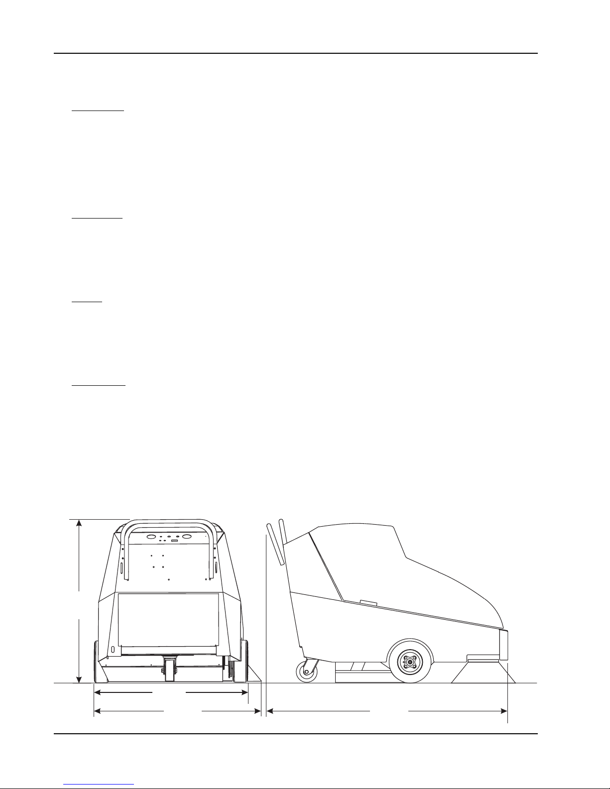
MACHINE SPECIFICATIONS........................................................................................................................ 1-3
MACHINE PREPARATION............................................................................................................................. 1-5
GAS/LP POWERED MACHINES ........................................................................................................... 1-5
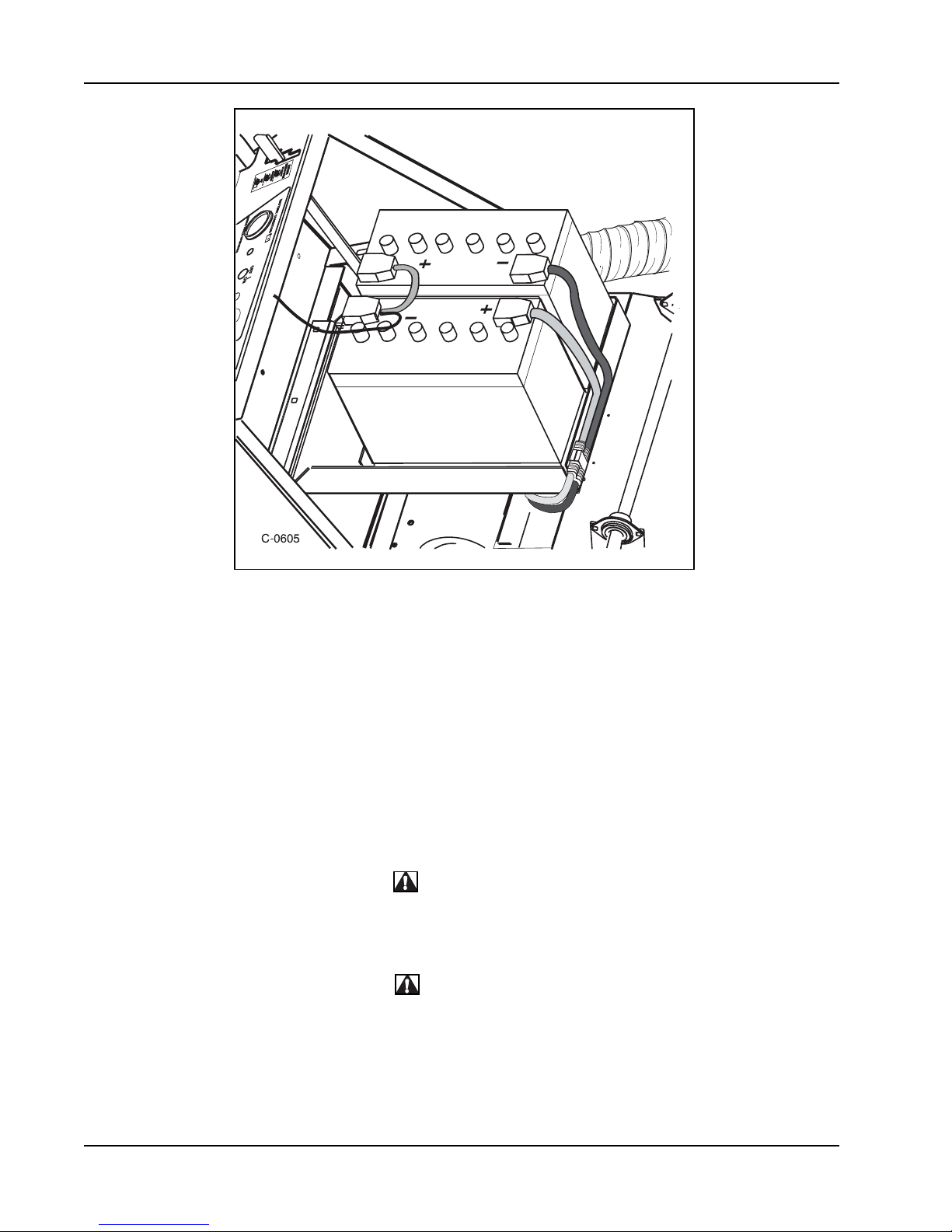
BATTERY POWERED MACHINES ........................................................................................................ 1-6
SAFETY PRECAUTIONS............................................................................................................................... 1-7
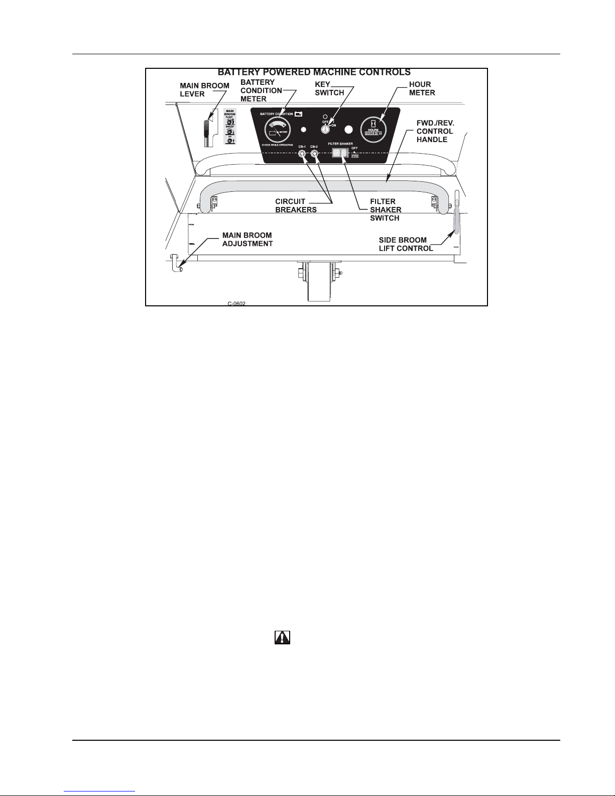
MACHINE CONTROLS .................................................................................................................................. 1-9
KEY SWITCH .......................................................................................................................................... 1-9
BATTERY CONDITION METER (BATTERY ONLY)................................................................................1-9
HOUR METER ......................................................................................................................................... 1-9
START BUTTON (GAS/LP ONLY)........................................................................................................... 1-10
BATTERY VOLT METER (GAS/LP ONLY) ............................................................................................. 1-10
CHOKE CONTROL (GAS/LP ONLY) ...................................................................................................... 1-10
LOW OIL LIGHT (GAS/LP ONLY) ........................................................................................................... 1-10
FILTER SHAKER SWITCH...................................................................................................................... 1-10
SIDE BROOM LIFT HANDLE.................................................................................................................. 1-11
MAIN BROOM LEVER ............................................................................................................................ 1-1
MAIN BROOM ADJUSTMENT ................................................................................................................ 1-11
FILTER MANIFOLD LATCH ..................................................................................................................... 1-12
HOPPER DUMP HANDLE ...................................................................................................................... 1-12
FORWARD/REVERSE CONTROL HANDLE ......................................................................................... 1-12
CIRCUIT BREAKERS .............................................................................................................................. 1-13
REWIND STARTER ................................................................................................................................. 1-13
OPERATING INSTRUCTIONS ...................................................................................................................... 1-14
BATTERY MACHINE OPERATION ......................................................................................................... 1-14
GAS/LP MACHINE OPERATION............................................................................................................ 1-14
PRE-START CHECKLIST ........................................................................................................................ 1-15
TO START THE BATTERY POWERED SWEEPER .............................................................................. 1-15
TO START THE GAS POWERED SWEEPER ......................................................................................1-15
TO START THE LP POWERED SWEEPER......................................................................................... 1-15
TO START THE ENGINE WITH THE REWIND STARTER ..................................................................... 1-16
TO DRIVE THE MACHINE FOR TRANSPORT ...................................................................................... 1-16
TO SWEEP WITH MACHINE ................................................................................................................. 1-16
TO EMPTY HOPPER .............................................................................................................................. 1-16
TO STOP SWEEPER ............................................................................................................................. 1-16
POST OPERATION CHECKLIST ............................................................................................................ 1-17
BATTERY CHARGING INSTRUCTIONS ................................................................................................. 1-17
TO CHARGE THE MOTIVE POWERED BATTERIES (BATTERY ONLY)............................................. 1-18
GASOLINE POWERED MACHINE FUELING INSTRUCTIONS ............................................................ 1-18
TO FILL THE GASOLINE POWERED MACHINE FUEL TANK ............................................................. 1-18
LP POWERED FUELING INSTRUCTIONS ............................................................................................ 1-18
TO CHANGE THE LP TANKS ................................................................................................................. 1-19
MACHINE STORAGE - GASOLINE POWERED MACHINES............................................................... 1-19
MACHINE STORAGE - BATTERY POWERED MACHINES ................................................................. 1-19
SERVICE CHART........................................................................................................................................... 1-20
HOW TO SWEEP .......................................................................................................................................... 1-22
SWEEPING GUIDELINES ...................................................................................................................... 1-22
SWEEPING VARIOUS TYPES OF DEBRIS.......................................................................................... 1-22
SERVICE INSTRUCTIONS............................................................................................................................ 1-23
MAIN BROOM ......................................................................................................................................... 1-23
TO CHECK THE MAIN BROOM SWEEP PATTERN .............................................................................1-23
TO ADJUST THE MAIN BROOM SWEEP HEIGHT ............................................................................... 1-23
TO REPLACE THE MAIN BROOM......................................................................................................... 1-24
SIDE BROOM .......................................................................................................................................... 1-25
TO CHECK THE SIDE BROOM SWEEP PATTERN.............................................................................. 1-25
TO ADJUST THE SIDE BROOM SWEEP HEIGHT................................................................................ 1-25
TO CHANGE THE SIDE BROOMS ........................................................................................................ 1-26
DUST CONTROL .................................................................................................................................... 1-26
TO CLEAN THE FILTER BAFFLE........................................................................................................... 1-26
TO CLEAN THE PANEL FILTER ............................................................................................................. 1-26
TABLE OF CONTENTS

1-2 American-Lincoln
91 WS
TO CHANGE THE PANEL FILTER.......................................................................................................... 1-26
FLAPS ..................................................................................................................................................... 1-27
TO ADJUST THE SIDE FLAPS ............................................................................................................... 1-27
HOPPER .................................................................................................................................................. 1-27
TO CLEAN THE HOPPER ...................................................................................................................... 1-27
TO CHECK THE HOPPER SEALS ........................................................................................................ 1-27
BATTERY ................................................................................................................................................. 1-27
ENGINE AIR INTAKE .............................................................................................................................. 1-28
FUEL FILTER ........................................................................................................................................... 1-28
TO CHECK THE ENGINE OIL LEVEL .................................................................................................... 1-29
DRIVE SYSTEM ...................................................................................................................................... 1-29
TO ADJUST NEUTRAL SETTING............................................................................................................ 1-29
‘ REPLACING THE FORWARD DRIVE BELT .......................................................................................... 1-29
REPLACING THE REVERSE BELT ....................................................................................................... 1-30
LP SAFETY PRECAUTIONS......................................................................................................................... 1-31
LP GAS SYSTEM .......................................................................................................................................... 1-32
LP LIQUID WITHDRAWAL SYSTEM...................................................................................................... 1-32
LP CHECKLIST........................................................................................................................................ 1-33
LP FUEL TANKS ..................................................................................................................................... 1-33
‘ USE AND CARE OF LP TANKS ............................................................................................................. 1-34
CHANGING LP TANKS ........................................................................................................................... 1-34
TO BEGIN CHANGING THE LP TANK ...................................................................................................1-34
STORAGE OF LP TANKS....................................................................................................................... 1-34
STANDARD HARDWARE & TORQUE VALUES........................................................................................... 1-35
DECIMAL METRIC & CONVERSION TABLE ...............................................................................................1-36
BOLT IDENTIFICATION ................................................................................................................................ 1-37
LEGENDS - SCREW/SETSCREWS.............................................................................................................. 1-38
HARDWARE LEGEND ................................................................................................................................... 1-39
ORDERING PARTS........................................................................................................................................ 1-42
TABLE OF CONTENTS - CHAPTER 2.......................................................................................................... 2-1
FRAME .................................................................................................................................................... 2-2
COVERS.................................................................................................................................................. 2-4
WHEEL DRIVE........................................................................................................................................ 2-6
LOWER WHEEL DRIVE ......................................................................................................................... 2-8
‘ MAIN BROOM ......................................................................................................................................... 2-10
MAIN BROOM ARMS.............................................................................................................................. 2-12
RIGHT HAND SIDE BROOM................................................................................................................... 2-14
HOPPER.................................................................................................................................................. 2-16
FILTER SHAKER ..................................................................................................................................... 2-18
IMPELLER ............................................................................................................................................... 2-20
BATTERY ................................................................................................................................................. 2-22
ENGINE ................................................................................................................................................... 2-24
ELECTRICAL ASSEMBLY (BATTERY) .................................................................................................. 2-26
ELECTRICAL ASSEMBLY (GAS) ........................................................................................................... 2-28
CONTROL PANEL ................................................................................................................................... 2-30
DECALS................................................................................................................................................... 2-34
TABLE OF CONTENTS - CHAPTER 3.......................................................................................................... 3-1
LEFT HAND SIDE BROOM OPTION ...................................................................................................... 3-2
LOW OIL SHUTDOWN OPTION ............................................................................................................. 3-4
FOAM-FILLED TIRE OPTION ................................................................................................................. 3-6
WET SWEEP BYPASS OPTION ........................................................................................................... 3-7
SPARE PARTS KITS............................................................................................................................... 3-8
MAIN BROOM OPTIONS ........................................................................................................................ 3-9
SCHEMATIC & CONNECTION DIAGRAMS (BATTERY) ....................................................................... 3-10
SCHEMATIC & CONNECTION DIAGRAMS (GAS)................................................................................ 3-11
INDEX ........................................................................................................................................................... 3-12
WARRANTY ................................................................................................................................................... 3-15
TABLE OF CONTENTS

American-Lincoln 1 - 3
91 WS
SWEEPINGPATH 36 inches (91.44 cm) with single side broom
45 inches (114.30 cm) with dual side broom
TRAVELSPEED 0-3 m.p.h.
DIMENSIONS
Length 60.00 inches (152.40cm)
Width 34.00inches(86.36 cm)
Height 39.00inches(99.06 cm)
Wheel Base 22.65 inches (57.79cm)
Track 32.00inches(81.28 cm)
WEIGHT (SHIPPING)
GasMachine 460 lbs. (171.58kg)
LPMachine 460lbs. (171.58 kg)
LPTank 20 lbs. (7.46 kg)
24VDC Machine 385 lbs.(143.61 kg)
Batteries 275lbs.(102.58 kg)
Charger 30 lbs. (11.19 kg)
WHEELS
RearCater(1) 2.0wide x5.00 dia. MoldedNon-marking Urethane
FrontDrive(2) 2.0 wide x 10.00 dia. (5.08 cm wide x 25.4 cm dia)
Solidgrey Non-markingRubber Standardor
3.0 wide x 10.00 dia (5.08 cm wide x 25.4 cm dia)
FoamFilled GreyNon-marking Rubber(Optional)
POWERSOURCES
24 VDC Battery
24 volt system, 1.3 HP (.97 kw) Electric Motor, (2) 12 volt batteries in series, 185A.H. @ 20 hour discharge
rating
Gas/LP
Briggs & Stratton 8 HP I/C Engine with electric and backup recoil start, Dual ElementAir Filter, 1.5 gal Fuel
Tank,LowOil Shutdown
Briggs & Stratton I/C Series
Model 1 cylinder, 8 HP (6 kw)
Bore 3 inches (7.62 cm)
Stroke 2.75 inches (6.98 cm)
Displacement 19.44 cu. inches (319.0 cc)
RPM 2200Max.
DRIVESYSTEM
Unitis self-propelled inforward and reverse,controlled byafull widthhandle bar,dual flat beltdrive toautomotive
typedifferential, chain drivewheels, beltdrivenmain andsidebrooms.
CONTROLSANDINSTRUMENTATION
Key Switch (with push button STAR for Gas/LP machines)
Forward/ReverseHandle
HourMeter
Ammeter(Gas/LP Models)
FuelGauge (Gas/LPModels)
ConditionMeter (Gas/LPModels)
SingleLever RaisesandLowers MainBroom
SingleLever Raises, Lowers,andActivates SideBroom
SPECIFICATIONS

1-4 American-Lincoln
91 WS
SWEEPINGSYSTEM
Type DirectThrow
MainBroom
One place plastic core disposable type. No tool charge. Position can be set to “Restricted Down” or “Free
Float”.
Length 27 inches (68.6 cm)
Diameter 11 inches (27.90 cm)
BristleLength 3 inches (7.62 cm) long, usable to 1.00 inch
Option BristleTypes Proes, Nylon, High Density Nylon
SideBroom
Rotarydisposabletype with 1.25inches (3.17 cm)thickmarine grade varnishedhardwooddisk. Floats over
uneven surfaces and is adjustable for wear. Retracts up to impact. No tool charge.
Diameter 16.00inches(40.60 cm)
BristleType Polypropylene
Hopper
Moldedpolypropylene construction withhandle todumpand leverstoremove (notool).
VolumetricCapacity 3 cu. ft. (85.00 It)
Weight Capacity 220 lbs. (82.06 kg)
GroundClearance 3 inches (7.62 cm)
DustControl
One pleated water resistant fibre type panel filter with automatic timed (20 seconds) filter shaker. Patented
shaker system. No tool quick change filter.
FilterArea 40 sq. ft. (3.70 m²)
Impeller 9 inches dia.
OPTIONALEQUIPMENT
LeftHand Side Broom LowOil Light
ShakerSwitch FoamFilled Tires in LieuofSolid Tires
MACHINEDIMENSIONS
SPECIFICATIONS
36.00"
91.44 cm 60.00"
152.40 cm
34.00"
86.36 cm
39.00"
99.06 cm
C0606

American-Lincoln 1 - 5
91 WS
MACHINEPREPARATION
YourAmerican-LincolnTechnologysweeper hasbeen shipped complete,but do notattempt to operatebefore
readingand following thepreparation instructions foryour typeofmachine.
GAS/LPPOWERED MACHINES
1. Uncratethemachine andcarefullyremove itfromthe skidtoprevent damage.
2. Inspectthe machine forobvious damage andcheck the controlsfor proper operation.
3. Connectand tighten batterycables.
4. Fillfuel tank withregular gradeunleadedgasoline.
*Install filled LP tank and connect fuel line to the tank.
*Turnonservice valve,checkall LPconnectionsfor leaks.
*Turnoff servicevalve afterinspection hasbeen completed.
5. Checkenginecrankcase oil level. Although properlylubricatedat the factory, check before startingengine.
The engine uses no special break in oil. The recommended number of hours before the initial oil change is 5
hours(see maintenance chart).
6. For safety, do not operate until you have read the safety precautions and operation instructions in the
manual.
*=LPPoweredmachines only
WARNING
To prevent possible fire, never fill fuel tank while the engine is running. Always be sure gasoline container and
sweeper are electrically grounded before dispensing gasoline. This can be done by permanently attaching an
insulated wire with a battery clip on the end to the gasoline container.
WARNING
Keep cigarettes, sparks, and open flame away from LP equipment.
Use extreme caution when inspecting for gas leaks.
MACHINE PREPARATION
C1199 FIGURE 1

1-6 American-Lincoln
91 WS
BATTERYPOWERED MACHINES
Thebatterypowered machines maybe shipped withthebatteries and chargerin separate containers. The
batteries will need to be filled with electrolyte if batteries were shipped dry.
1. Uncratethemachine andcarefullyremove itfromthe skidtoprevent damage.
2. Inspectthe machine forobvious damage andcheck the controlsfor proper operation.
3. Connect and tighten battery cables. (See Figure 2)
4. Connect battery cables. Be sure to observe polarity. (See Figure 2)
5. Charge batteriesusing thequickdisconnect provided. Leavethe top coveropen whilechargingto prevent
buildupof explosivegasesgenerated during thecharging process. Refer tothecharging instructions
providedinthe manualandon thechargingunit beingused.
6. For safety, do not operate until you have read the safety precautions and operation instructions in the
manual.
WARNING
Lead acid batteries generate gases which can cause an explosion. Make sure the switch on the charger is in the
“OFF” position before connecting or disconnecting the charger. If no switch is provided, unplug the charger before
making connections to the batteries. Keep sparks and flame away from batteries. NO SMOKING. Charge the
batteries only in an area with good ventilation and leave the top cover open while charging.
WARNING
Batteries contain sulfuric acid which can cause burns to exposed skin or eyes. To prevent injury, wear protective
clothing and safety glasses when working on batteries. In the event that acid comes in contact with skin or eyes,
flush affected area with fresh water for a minimum of 5 minutes and get medical attention immediately.
MACHINE PREPARATION
C0605 FIGURE 2

American-Lincoln 1 - 7
91 WS
SAFETYPRECAUTIONS
Thefollowing statementsareusedthroughoutthismanualasindicatedintheirdescriptions:
DANGER
To warn of immediate hazards which will result in severe personal injury or death.
WARNING
To warn of hazards or unsafe practices which could result in severe personal injury or death.
CAUTION
To warn of hazards or unsafe practices which could result in minor personal injury.
ATTENTION
To warn of unsafe practices which could result in extensive equipment damage.
NOTE
To give important information or to warn of unsafe practices which could result in equipment damage.
THE FOLLOWINGINFORMATIONSIGNALS POTENTIALLYDANGEROUS CONDITIONSTOTHEOPERA-
TOR OR EQUIPMENT. READ THIS MANUAL CAREFULLY. KNOW WHEN THESE CONDITIONS CAN EXIST.
THEN,TAKENECESSARYSTEPSTOTRAINMACHINE OPERATING PERSONNEL.
FOR THE SAFE OPERATION OF THIS MACHINE, READ AND UNDERSTANDALL WARNINGS. CAUTIONS
ANDNOTES.
WARNING
Machines can ignite flammable materials and vapors. Do not use with or near flammables such as: gasoline, grain
dust, solvents and thinners.
WARNING
Heavy machinery. Improper use can cause personal injury.
WARNING
Operate only when lids, doors, and access panels are securely closed.
WARNING
Use care when reversing machine in confined area.
WARNING
When servicing the machine disconnect the batteries first to prevent possible injury.
WARNING
When working on the machine, empty hopper, remove batteries, clear area of people and obstructions, use
additional people and proper procedures when lifting the machine.
WARNING
Always empty the Hopper and Disconnect Battery before doing maintenance.
WARNING
You must have training in the operation of this machine before using it. READ THE INSTRUCTION BOOK.
WARNING
Do not operate this machine unless it is completely assembled.
SAFETY PRECAUTIONS

1-8 American-Lincoln
91 WS
WARNING
Do not use this machine as a step or furniture.
WARNING
Be careful when operating the machine on a ramp or incline. Always move slowly on a ramp. Do not turn this
machine on a ramp. Do not stop and leave this machine on a ramp.
WARNING
Stop and leave this machine on a level surface. When you stop the machine, put the key switch in the “OFF”
position.
WARNING
To prevent injury, and damage to the machine, do not lift the machine or move it to an edge of a stair or loading
dock.
WARNING
Lead acid batteries generate gases which can cause an explosion. Keep sparks and flames away from batteries.
NO SMOKING. Charge batteries only in area with good ventilation and always leave the top cover open while
charging batteries. Do not disconnect the charger from the batteries before disconnecting the AC power cord.
Disconnecting the battery cable with the charger plugged in could cause an explosion.
WARNING
Always wear eye protection and protective clothing when working near batteries. Remove all jewelry. Do not put
tools or other metal objects across the battery terminals, or the tops of batteries.
WARNING
Maintenance and repairs must be done by authorized personnel only. Tighten all fasteners. Keep adjustments
according to the specifications given in the service manual for the machine. Keep the electrical parts of the
machine dry. For storage, keep the machine in a building.
WARNING
Make sure that all labels, decals, warnings, cautions and instructions are fastened to the machine. Get new labels
and decals from American-Lincoln.
SAFETY PRECAUTIONS

American-Lincoln 1 - 9
91 WS
MACHINECONTROLS
KEYSWITCH
The key switch is a two position rotary ON/OFF switch that is located on the control panel.
The filter shaker will activate for 20 seconds after the key switch is turned to the “OFF” position unless equipped
with the optional filter shaker switch.
Gas/LP Powered Machines
The key switch must be turned “ON” before using the electric starter button or the pull start.
-Turn the key switch to the “ON” position before using the start button.
-Turn the key switch to the “OFF” position to turn off the sweeper.
Battery Powered Machines
Toconservebattery powerturnthe keyswitch“OFF” whenleavingthe machineunattendedeven ifonlyfor a
minute.Runtime forthebattery poweredmachinecan varywithoperating conditionsandmachine maintenance
practices.
-Turn the key switch to the “ON” position to turn on the sweeper.
-Turn the key switch to the “OFF” position to turn off the sweeper.
BATTERYCONDITION METER (Battery Powered Machines)
The battery condition meter is located on the left side of the console. The condition meter indicates the level of
charge in the batteries. The batteries are sufficiently charged when the needle stays in the green area on the
gaugewhilethe machineisbeing operated. Chargethebatteries whentheneedle drops intothe red zonewhile
operatingthe machine.
WARNING
Do not operate the machine if the needle stays in the red zone. Operating the sweeper with discharged batteries
will degrade battery life.
HOURMETER
The Hour Meter is located on right side of the console. The meter is activated when the key switch is on. The
meter indicates actual run time of the sweeper.The meter is used to determine when maintenance should be
performed.
MACHINE CONTROLS
C0602 FIGURE3

1-10 American-Lincoln
91 WS
START BUTTON (Gas/LP Only)
The start button is located on the right side of the console next to the key switch. The start button is a momen-
tary push button switch that energizes the electric starter motor when pushed. The key switch must be turned
on before using the start button to start the engine.
WARNING
Do not hold the start button for more than 15 seconds at a time. Allowing the starter motor to run for more than 15
seconds at a time may cause permanent damage to the starter motor.
To start the engine, push and hold the switch until the engine starts.
BATTERYVOLT METER (Gas/LP Only)
The battery volt meter is used to monitor the charging system on GAS/LP Powered machines.
Themeterindicates the voltageof thebattery.Aproperly chargedbatterywill indicate approximately13.8volts.A
reading of less than 12 volts could be an indication of a charging system fault.
CHOKECONTROL (Gas/LPOnly)
The choke control is located on the console. The choke governs the air/fuel mixture during the combustion cycle
oftheengine operation.Thechoke shouldbepulled out whilestarting the engineandthen graduallypushed
back in after the engine warms up.
LOW OIL LIGHT (Gas/LP Only)
The low oil light is located on the console. The low oil light is part of a protection feature for the engine. When
theoillevel drops below asafe level the engineshutsoff and illuminates thelight to advise theoperatorof the
low oil level. When this occurs check the oil level in the engine and add oil as necessary. The oil level must be
fullbeforethe engine willstart.
FILTER SHAKERSWITCH
The filter shaker switch is a two position rocker switch that is located on the console. When the filter shaker
switch is set to the “ON” position the filter shaker will operate automatically for approximately 20 seconds after
the key switch is turned off. The “OFF” position disables the automatic shake cycle which would normally occur
after turning the key switch off.
LOW OIL
FLOAT
SWEEP
UP
MAIN
BROOM
MAIN
BROOM
CHOKE START
CB-1 CB-2 FILTER SHAKER
OFF
OFF
ON
BATTERY
10
12 14
16
0 0 0 0 0
HOURS
MAIN BROOM
LEVER
MAIN BROOM
ADJUSTMENT
BATTERY
VOLT
METER
KEY
SWITCH
START
BUTTON
CHOKE
CONTROL
G
A
S/
LP P
O
WERED MA
C
HINE
CO
NTR
O
L
S
HOUR
METER
LOW
OIL
LIGHT
FWD./REV.
CONTROL
HANDLE
FILTER
SHAKER
SWITCH
CIRCUIT
BREAKERS
SIDE BROOM
LIFT CONTROL
C-0601
MACHINE CONTROLS
C0601 FIGURE4

American-Lincoln 1 - 11
91 WS
SIDEBROOM LIFTHANDLE
The Side Broom lift handle is located at the rear of the
sweeperonthe right side.The lift handleraisesand lowers
the side broom. Broom rotation stops when the side broom
is raised.
-To raise the side broom, pull the handle out and down to
lock the broom in the raised position.
-To lowerthe sidebroom,move handleup andforwardinto
the slot.
MAINBROOM LEVER
The main broom lever is located on the left side of the
console.Themain broomleverhas three positionsthat
controlthemain broomsweepheight.
To lowerthemain broom, graspthelever and moveit to the
right out of the “UP” position and place the lever in the
“SWEEP”or“FLOATposition.
The“SWEEP”position isfornormal sweeping andshould
beusedfor most sweepingconditions.
The“FLOAT”positionisusedforsweepingveryuneven
surfaces only. Using the float position will cause premature
wearon the mainbroom ifusedunder normaloperating
conditionsforextended periodsoftime.
MAINBROOM ADJUSTMENT
The main broom adjustment is located at the rear of the
machine.Adjust the mainbroomsweep height to compen-
sate for wear of the broom bristles. Check the main broom
sweepheightregularly and adjustasnecessary.(See “Main
BroomService” in thismanual)
TO LOWER
BROOM
C0613/9705
MAIN BROOM
ADJUSTMENT
TO RAISE
BROOM
C-0611
MACHINE CONTROLS
C0611 FIGURE 5
C0612 FIGURE 6
C0613 FIGURE 7

1-12 American-Lincoln
91 WS
FILTER MANIFOLD LATCH
Thefiltermanifold latch is locatedonthe hinged filter
manifoldassembly.Thelatchmust bedisengagedbefore
dumpingthehopper orremovingthe dustfilter.Apply slight
downpressureon the edgeof the manifold assemblyto
easeremoval.
To disengagethefilter manifold latches,apply slight down
pressure to the manifold assembly and lift the latch off the
catch.
HOPPERDUMPHANDLE
Thehopperdump handleislocated on thehopper and is
usedfor dumping debris.Amechanical interlock prevents
thehandle from beingmoved out ofthe stowed position
beforethe filter manifoldassembly has beenlifted away from
thehopper.
To dump the hopper, disengage the filter latch, lift the
manifoldassemblythen rotate the dumphandle out of the
stowed position and lift.
To stow the handle, replace the handle to the stowed
position,lowerthe filtermanifoldassembly andengagethe
filter latch.
FORWARD/REVERSECONTROLHANDLE
Theforward/reverse controlhandleis locatedat therear of
themachine.The controlhandleextending across therear
ofthemachine activatesthebelt driven dead-manclutch in
thedrivesystem.
Todrivethemachineforward,movethe controlhandle
forward.
Todrivethe machinebackward, movethe controlhandle
back.
Thehandle returns toneutral automaticallywhenreleased.
FLOAT
SWEEP
UP
MAIN
BROOM
MAIN
BROOM
CB-1
CB-1
CB-2
CB-2
FILTERSHAKER
FILTER SHAKER
BATTERYC
ONDITION
BATTERYCONDITION
CHECKWHILEOPERATING
CHECK WHILE OPERATING
OFF
OFF
OFF
OFF
ON
ON
-
+
FORWARD/REVERSE
CONTROL HANDLE
FORWARD
REVERSE
NEUTRAL
1
34
2
HOPPER
DUMP
HANDLE
LIFT
HANDLE
TO DUMP
HOPPER
LIFT
HANDLE
TO DUMP
HOPPER
HOPPER
DUMP
HANDLE
C0614 FIGURE 10
C0608 FIGURE 9
C0609 FIGURE 8
MACHINE CONTROLS

American-Lincoln 1 - 13
91 WS
CIRCUITBREAKERS
Thecircuit breakers provideprotection fortheelectrical
system and are located on the console. The circuit breaker
“POPS”outwhen anovercurrentcondition exists.
When a circuit breaker pops out, the machine must be
takenout of serviceand repairedbeforethe circuitbreaker
will reset. The circuit breaker may be reset when the
overcurrentcondition hasbeen corrected.
Push the button in to reset a popped circuit breaker.
REWINDSTARTER
TheGas/LPengine isequipped with arewindstarter. If the
battery is dead, it may be possible to start the engine with
therewind starter.
Open the top cover to gain access to the rewind starter.
To use therewindstarter:
-Turn key switch to “On” position.
-Grasp the starter, and pull it slowly until the starter en-
gages.
-Pullthe cord rapidlyenough to overcomecompression,
preventkickbackand startengine.
CHOKE START
CB-1 CB-2 FILTER SHAKER
OFF
OFF
ON
BATTERY
10
12 14
16
0 0 0 0 0
HOURS
CIRCUIT
BREAKERS
C-1161
P4550 FIGURE 12
C1161 FIGURE 11
MACHINE CONTROLS

1-14 American-Lincoln
91 WS
BATTERYMACHINEOPERATION
Charge the batteries after operating the machine. See the battery charging instructions in this manual. Use the
pre-start checklist and follow the service chart for daily check points. Read and follow the safety precautions to
assuresafe, troublefreeoperation.
WARNING
Lead acid batteries generate gases which can cause an explosion. Keep sparks and flames away from batteries.
NO SMOKING. Charge batteries only in area with good ventilation and always leave the top cover open while
charging batteries. Do not disconnect the charger from the batteries before disconnecting the AC power cord.
Disconnecting the battery cable with the charger plugged in could cause an explosion.
WARNING
Always wear eye protection and protective clothing when working near batteries. Remove all jewelry. Do not put
tools or other metal objects across the battery terminals, or the tops of batteries.
GAS/LPMACHINE OPERATION
See the LP instructions in this manual for fueling and service instructions on the LP fuel system and replace-
ment of tanks. Use the pre-start checklist and follow the service chart for daily check points. Read and follow the
safetyprecautions to assuresafe, troublefreeoperation. Gasolinepoweredmachines useregular grade un-
leadedgasoline. Turntheengine offbefore dispensingfuel intothegasoline poweredmachine.
WARNING
To prevent possible fire. Never fill fuel tank while the engine is running.Always be sure gasoline container and
sweeper are electrically grounded before dispensing gas. This can be done by permanently attaching an insulated
wire with a battery clip on the end to the gasoline container.
WARNING
All internal combustion engines give off harmful fumes and gases while running. Do not start or run the engine in
an enclosed area where the exhaust gases can accumulate. Avoid breathing these gases as they contain poison-
ous carbon monoxide which can endanger your health or life if inhaled steadily for even a few minutes.
WARNING
Check for gas odor before and during starting operations. If gas odor is noticed, stop and check for leaks or
component malfunctions in the fuel system. Check fuel supply hoses for proper connection and signs of abrasion.
Do not start engine when gas odor is present.
WARNING
Keep cigarettes, sparks and open flame away when working on LP equipment, use caution when inspecting for
gas leaks or when LP tanks are present.
WARNING
Do not run engine in an enclosed area. exhaust gases contain carbon monoxide, an odorless and deadly poison.
Do not operate the engine without adequate ventilation.
OPERATING INSTRUCTIONS

American-Lincoln 1 - 15
91 WS
STARTING INSTRUCTIONS
PRE-START CHECKLIST
Before starting the machine, do these pre-start checks.
1. Checkall controls forproper operation.
2. Checkfor loose battery connections.
3. Make sure all controls are “OFF”.
4. Checkto be certain thattheforward /reverse control handleis centered in theneutralposition.
TOSTART THE BATTERYPOWERED SWEEPER
Performthepre-startchecklistbefore startingthe sweeper.
1. Turn the key switch to the “ON” position.
2. Check the battery condition meter after the machine is on to determine if battery is sufficiently charged.
Charge the batteries when the needle stays in the red zone while the machine is being operated
TO START GAS POWERED SWEEPER
Follow these instructions for starting a cold engine. If the engine is warm reduce the initial choke setting in step
1 to halfway out position.
1. Set the choke to the full out position.
2. Turn the key switch to the “ON” position.
3. Push the start button until the engine starts. Do not hold the start button for more than 15 seconds at a
time.
4. After engine starts, gradually push in the choke until the engine runs smoothly.
5. If the engine starts then stalls push in the choke halfway and restart the engine.
6. Attemperatures below 50°F(10° C), aoneor two minutewarm-upmay be required.
7. Pushthe choke controlallthe way inwhenthe engine reachesnormaloperating temperature.
TO START LP POWERED SWEEPER
Follow these instructions for starting a cold engine. If the engine is warm reduce the initial choke setting in step
4 to halfway out position.
1. Openthe LP storagetank valve.
2. Check all propane components for leaks and physical security. Be sure the tank is securely fastened.
3. Check the regulator. Momentarily press fuel primer on the regulator cover to bleed air out of the system.
4. Set the choke to the full out position.
5. Push the start button until the engine starts. Do not hold the start button for more than 15 seconds at a
time.
6. If the engine starts then stalls, push in the choke halfway and restart the engine.
7. At temperatures below 50° F (10° C),a one ortwo minute warm-up mayberequired.
8. Pushthe choke controlallthe way inwhenthe engine reachesnormaloperating temperature.
TOSTARTENGINE USINGTHE REWIND STARTER
The Gas/LP engine is equipped with a rewind starter. If the battery is dead, it may be possible to start the
engine with the rewind starter. Grasp the starter, and pull it slowly until the starter engages. Pull the cord rapidly
enoughtoovercome compression, preventkickback and startengine.Repeat if necessarywith the choke
opened slightly. When the engine starts open the choke gradually to position that allows the engine to run
smoothly.
OPERATING INSTRUCTIONS

1-16 American-Lincoln
91 WS
TODRIVE MACHINEFOR TRANSPORT
Use these instructions to drive the machine for transport to the sweeping site.
WARNING
Be careful when operating the machine on a ramp or incline. Always move slowly on a ramp. Do not turn this
machine on a ramp. Do not stop and leave this machine on a ramp.
1. Pushthe Forward/Reversecontrol Handleforwardtostartmachine moving.
2. Vary yourhand pressure onthecontrol handle toobtainthe desiredtravel speed.
TO SWEEP WITH MACHINE
Follow these steps to sweep with the machine.
WARNING
Machines can ignite flammable materials and vapors. Do not use with or near flammables such as: gasoline, grain
dust, solvents and thinners.
1. Lowerthe side broom.
2. Movethe main broomlever to thesweep position.
3. Vary yourhand pressure onthe forwardreversecontrol handleto obtaindesired travelspeed.
4. Emptythe hopper when full.The sweeper will startto leave debris onthefloor when thehopperfills to
capacity.
TOEMPTY HOPPER
Emptythehopper whenfull.The sweeper maybeginto leaveatrail of debriswhile sweeping whenthehopper is
full.Usethe hopperdumphandle to emptythe hopper.The hoppermay be removedforcleaning. Do notattempt
toremovethe hopperwhenfull. Emptythehopper beforeremoving.Follow theseinstructionsto dumpthe
hopper.
WARNING
To prevent possible back injury. Do not attempt to dump the hopper if it is too heavy to be lifted by one person. Get
help if needed. Know how to lift safely. Use your legs to do the work while keeping your back straight in an upright
position. Do not bend over and use your back to lift heavy objects.
1. Drive to dump site and position machine on hard level surface. Turn key switch to the “OFF” position.
2. Openthe hingedtop cover.
3. Disengage the filter manifold latch located on the filter shaker assembly.Apply light down pressure on the
corner of the shaker assembly to ease removal of the latches.
4. Liftthe hingedshakerassembly away fromthe hopper.
5. Swingthe hopper dumphandleto the dumpposition.
6. Lift the hopperdump handle toemptythe hopper.
7. Usethe hopper dumphandleto return thehopperto the sweepposition.
8. Swingthe hopper dumphandleto the stowedposition.
9. Lowerthe hinged shakerassemblyand engage thefiltermanifold latch.Apply slightdown pressure on the
cornerofthe shaker assemblytoease engagement.
10. Close thehinged topcover.
TO STOP SWEEPER
1. Allowthe directional control handletoreturn to the center(neutral)position.
2. Use the side broom lift handle to raise the side broom. Pull out and down to lock the side broom in the
raisedposition.
3. Usethe main broom levertoraise the main broom.Movethe main broomleverback to the “UP”positionand
movethelever into theslotprovided to holdthe main broom inthe “UP” position.
4. Turn the key switch to the “OFF” position.
5. Perform the post operation checklist.
OPERATING INSTRUCTIONS

American-Lincoln 1 - 17
91 WS
POSTOPERATION CHECKLIST
Afterstoppingthe machine performthese post operation checks.
1. Checksweepingbrooms forwear ordamage.
2. Checkallflapsforwear, damageor adjustment.
3. Close the supply valve on the LP cylinder. Check the fuel level and install a filled cylinder if needed.
~3. Fill the fuel tank.
*3. Chargethe batteries.
4. Performthescheduled maintenanceaccordingto theservicechart.
- = LP powered machines only.
~=Gasolinepowered machinesonly.
* = Battery powered machines only.
BATTERYCHARGINGINSTRUCTIONS
Charge the batteries at the end of each day or when the battery condition meter indicates low battery voltage.
The batteries need to be charged when the needle stays in the “red” zone while the machine is being operated.
When charging batteries, only use the quick disconnect provided. Use the quick disconnect to insure correct
polarity.
Check the liquid level in the batteries a least once a week and add water when low. Use only distilled water. Fill
thebatteriesafter charging the batteriestoprevent electrolyte from spillingoveron to the topsof the batteries
duringthe charging process.
WARNING
The use of an extension cord with the charger should be avoided. Risk of fire and electrical shock is possible if the
wrong type or size extension cord is used. If an extension cord must be used, only use a three conductor number
12AWG cord with ground, properly wired, in good electrical condition and keep it as short as possible. Locate all
cords so that they cannot be stepped on, tripped over, or otherwise subjected to damage or stress.
WARNING
Verify that the AC power source to which the charger is to be connected is capable of supplying the current
specified on the charger nameplate.
WARNING
Keep all charger ventilation holes at least 2 inches away from walls or other objects. Do not allow vent holes to
become obstructed.
WARNING
Do not operate charger that has been damaged or shows physical signs of damage. Have charger serviced by a
qualified professional repair person.
WARNING
Lead acid batteries generate gases which can cause an explosion. Keep sparks and flames away from batteries.
NO SMOKING. Charge batteries only in area with good ventilation and always leave the top cover open while
charging batteries. Do not disconnect the charger from the batteries before disconnecting the AC power cord.
Disconnecting the battery cable with the charger plugged in could cause an explosion.
OPERATING INSTRUCTIONS

1-18 American-Lincoln
91 WS
TO CHARGE THE MOTIVE POWER BATTERIES (Battery powered machines only)
1. Readthe detailedinstructions provided onthe charger.
2. Be sure all controls are “OFF” and machine is located in an area with good ventilation.
3. Openthetop cover.The topcover must remainopen during thecharging process.
4. Disconnect the machine power supply cable from the battery using thequickdisconnect provided.
5. Connectthe charger cable to thebatteryconnector.
6. Plugthe charger intoproperlygroundedAC outlet. Besureto verify theoperatingvoltageofyourcharger.The
chargerssuppliedwith machine operate at115 VAC @60 HZ or230VAC@ 50 HZ.
7. Thechargerwill beginchargingthe batteries afterashort periodoftime. The chargerwill shut offautomati
cally when the charging process is complete.
8. Unplugthe charger fromthe groundedACoutletbefore disconnectingthecharger fromthe battery.
9. Disconnectthe charger cablefromthe battery.
10. Check theelectrolytelevel in the batteryafter charging.Add distilled water if needed.
11. Reconnect the machine power supply cable to the battery cable.
12. Lower thetop coverandperform thepre-startchecks beforeoperating the machine.
GASOLINEPOWERED MACHINE FUELINGINSTRUCTIONS
Thefueltank for gasoline powered machinesis located on the engine.Thetop cover must beopenedto access
thefueltank.Afteropening thetopcover,observe the combinationfuelcap/gas gauge andcheck the fuellevelto
determine if the fuel tank needs to be filled.
TO FILL THE GASOLINE POWERED MACHINE FUELTANK
WARNING
To prevent possible fire. Never fill fuel tank while the engine is running.Always be sure gasoline container and
sweeper are electrically grounded before dispensing gas. This can be done by permanently attaching an insulated
wire with a battery clip on the end to the gasoline container.
1. Turn the key switch to the “OFF” position.
2.Openthe topcover.
3. Observe the level indicated by the gas gauge on the fuel tank cap.
4.Removethe fuel tank capfromthe fuel tank andaddgasoline as needed.
5. Install the gas cap and lower the hinged top cover.
LPPOWERED MACHINEFUELING INSTRUCTIONS
Fueling the LP powered machine is accomplished by removing the empty LP cylinder and replacing it with a full
replacementcylinder. Some cylindersare equipped witha fuel levelgauge.Check thegaugeand changethe
cylinderwhenthe gauge reads“EMPTY”. See theLPInstructions in thismanualfor additional information.
WARNING
Improper filling procedures could cause an explosion. Have your LP cylinders filled by qualified personnel.
WARNING
Park the machine in a safe area designated for changing LP fuel tanks. The designated safe area must have
adequate ventilation, must be free from sparks or other sources of ignition.
WARNING
NO SMOKING signs should be posted and enforced. The area must not be in the vicinity of flammables, combustible
materials or high temperature sources such as furnaces or ovens.
WARNING
Always store and transport LP fuel tanks with the safety relief valve in the up position. This will prevent the tank
from venting liquid propane in the event the safety relief valve opens due to overpressure in the tank. A properly
stored tank will only vent gaseous propane which dissipates much faster than liquid propane.
OPERATING INSTRUCTIONS

American-Lincoln 1 - 19
91 WS
TOCHANGE LPTANK
The tank changing operation presents an opportunity for the operator to inspect the tank, tank fittings and the
fuel lines for damage or wear that could cause leaks in the LP fuel system. Follow these steps to change the LP
tank.
1. Park the machine in a designated safe area.
2. Turn key switch to “OFF” position.
3. Closethe tank supplyvalve.
4. Removethe machine fuel supply hosequickdisconnect coupling from the tank.
5. Inspectthefuel systemcomponentsfordamageand abnormalwear.
6. Removethe tank fromthecradle holding device. Handlethe tank carefully. Itmust not be droppedor
mishandled.
7. Store the empty tank in the designated storage area.
8. Select a filled LP tank and inspect for damage and abnormal wear.
9. Carefully install the tank so the centering pin aligns with the hole in the tank collar.
10. Fasten the tank hold down clamp so that the tank locks into position.
11. Reconnect the machine fuel supply hose to the tank supply coupling.
12. Open thetanksupply valveandinspect for leaks. If leaksarepresent close the supply valveimmediately.
Investigatethesource oftheleak and haveit repaired beforeusingthe machine.Ifno leaks arefound, the
machine is ready to start.
13. Close thetop cover.
14. Close the tank supply valve if the machine is to be stored.
MACHINESTORAGE
GASOLINEPOWEREDMACHINES
Machinestobe stored over30 days shouldbecompletely drained offuel to preventgumdeposits forming on
essentialcarburetorparts, fuel filterand tank.
Theuseof a fueladditive, such as STA-BIL, oranequivalent, will minimizetheformation of fuelgum deposits
during storage. Such an additive may be added to the gasoline in the fuel tank of the engine.
Thefollowing procedureshouldbe usedto preparethemachine forstorage:
1. All fuel should be removed from the tank. Run the engine until it stops from lack of fuel.
2. While engine is still warm, drain oil from the crankcase. Refill with fresh oil.
3. Removespark plug, pour approximately1/2ounce (15 grams) ofengine oil into cylinderandcrank slowly to
distribute oil. Replace spark plug.
4. Store in a clean and dry area.
BATTERYPOWEREDMACHINES
All wet batteries will slowly discharge on standing and will discharge much faster when warm than when cold.At
normal temperature of 80°F (26°C) loss of capacity by self-discharge, starting with a fully charged battery, may
amounttoan averageof.001 specificgravityper dayovera 30 dayperiod. The batteryshould be givena booster
chargewhenthe specificgravityfalls .040.
Donotdischarge thebatteriesexcessively.Excessive discharge cancause polarity reversalofthe individual
cells in the battery which will lead to complete failure of the batteries.
Use a hydrometer to monitor the specific gravity of the individual cells in the batteries. When checking the
specificgravityof thebatteries,you should notseea largedifferencebetween the individualcells. The batteries
may need to be replaced if the battery shows a significant difference of specific gravity between the cells.
Thespecificgravity oftheelectrolyte shouldmeasure1.285 whenfullycharged.
OPERATING INSTRUCTIONS
Table of contents
Other Alto Blower manuals
Popular Blower manuals by other brands

Worx
Worx WG500.2 manual

Echo
Echo ES-210 - PARTS CATALOG SERIAL NUMBER P11012001001 -... parts catalog

Floorwash
Floorwash MB38 Original instruction manual

Homelite
Homelite UT09523 Replacement parts list

Stanley
Stanley Fatmax SFMCBL7M1 manual

Lennox Hearth Products
Lennox Hearth Products CI1500 installation instructions