3
www.altrex.com
EN
1. Introduction
Thismanualappliesexclusivelytofoldingandrollingtowercongurations(hereinafter:‘thescaold)asdescribedinthis
assembly&usermanual(hereinafter:‘themanual’).Priortostartingtoassemblethetower,youshouldcarefullyreadthisma-
nual. The required tower should be assembled and used in accordance with this manual.All instructions in this manual have to
befollowedstrictly.Notfollowingtheinstructionscontainedinthismanualcaneasilyresultinseriousaccidents.Altrexcannot
beheldliableforanylossresultingfromtheassemblyoruseofanAltrextowerthatisnotincompliancewiththemanual.The
employer,supervisoranduserareresponsibleforthecorrectuseofthetowerinaccordancewiththismanualandtheymust
ensure that this manual is available at all times when work is being carried out using the tower. Additional copies of the manual
can be ordered from Altrex.
Local legislation and regulations might encompass measures in addition to those stated in this manual.
AltrexBV–Mindenstraat7–8028PKZwolle–T
el.:+31(0)384557733–Email:
[email protected]–Internet:www
.altrex.com
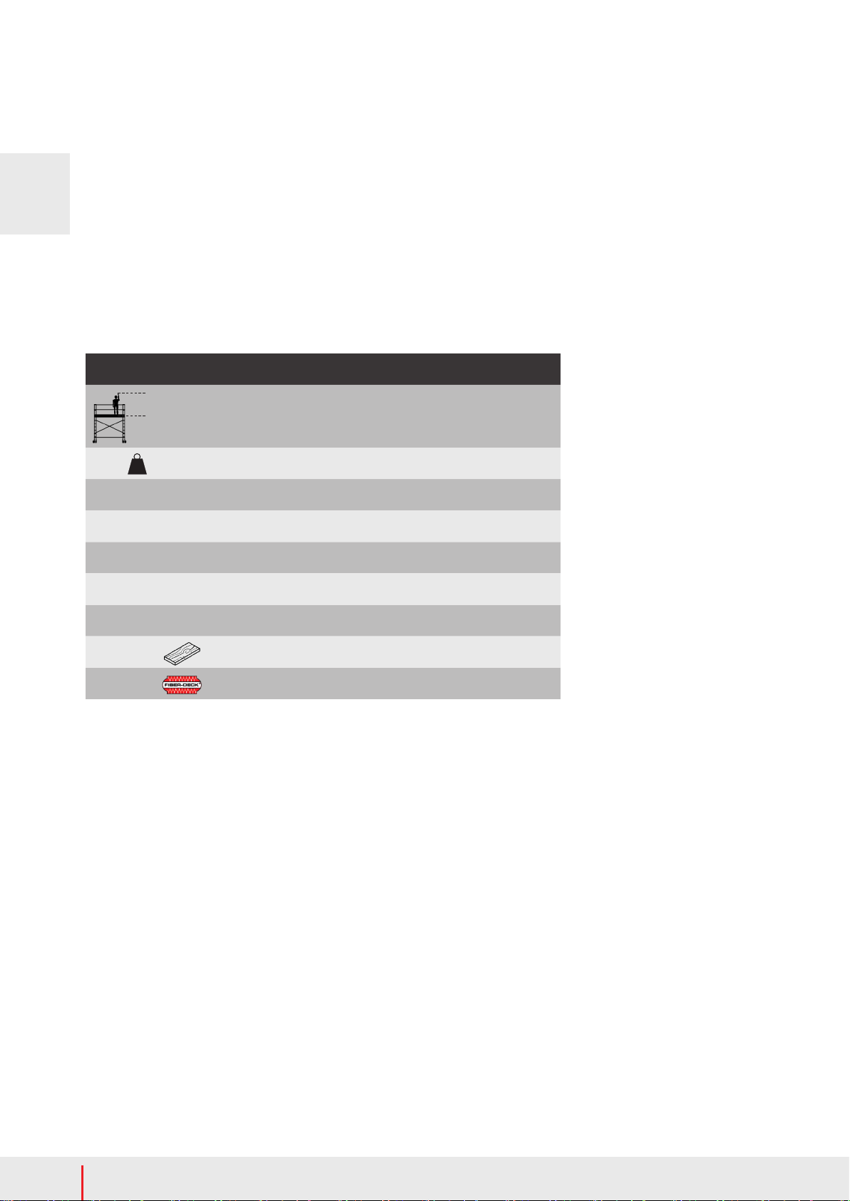
2. Type of rolling tower
MiTOWER MiTOWER+
Norm EN1004 EN1004
Category 3 - H2 3 - H2
Accesscategory XXCD XXCD
Maximum platform height outdoors 4 m 6 m
Maximum platform height indoors 4 m 6 m
Maximum platform load 150 kg 240 kg
Maximum load on rolling tower 750 kg 750 kg
Max number of platforms to be loaded 1 2
Maximum wind load 7,9m/s
(max.4Beaufort*) 7,9m/s
(max.4Beaufort*)
Minimumnumberofassemblypersons 1 1
3. Safety instructions
1. Thelocationoftherollingtowermustbecheckedtopreventaccidentsduringassembly,dismantlingandmovingwithrespectto:
A. Ahorizontal,atandsolidbase;
B. Thelocationmustbefreeofobstacles;
C. Maximum allowed wind speeds.
2. Checkifallrequiredparts,toolsandsafetytools(ropes,etc)forassemblingtherollingtowerareavailable.
3. Therollingtowermustnotbeoutoftheplumbinexcessof1%.Therefore,ataheightof4meters,thedeviationmaynotexceed4cm.
4. Theuseofhoistinggearonorattachedtotherollingtowerisnotpermitted;thiscanseriouslyaectthestabilityofthetower.
Rollingtowerparts,toolsandmaterialsmayonlybebroughtupanddown(toandfromtheworkoor)manuallyusingarope,for
example.
5. Checkallpartsfordamage.Damagedorincorrectpartsmaynotbeused.Mixingrollingtowerpartsofdierentbrands/from
dierentmanufacturersisnotpermitted,becausestrength&stabilitycalculationwasnotcarriedoutforthemixedconguration
concerned.
6. Thestandardcongurationsinthismanualarenotcalculatedontheuseoftarpaulinsand/oradvertisingboards.
7. Neverleavetherollingtowerunsupervised.Iftherollingtowermustbeleftunsupervised,youhavetomakesurethat
unauthorisedindividualscannotaccessit.Anchorthetowerwith2anchoragetubes(309106)ifthereisachangethatwindspeed
mightexceed4Beaufort*duringtheunsupervisedperiodoftime.
8. Particularattentionshouldbepaidtousingrollingtowerswhenthereiswind:
- withaspeedgreaterthan7,9m/s(maximum4onthescaleofBeaufort*);takealsointoaccountsquallsandgusts.
- inareasthatareverysensitivetowinde.g.,inopenconstructionsandatthecornersofabuilding.
Inthesecases,therollingtowermustbedisassembledormovedtoawind-freeplace.
9. Lateralloadsexceeding30kgresultingfromworkactivitiesontherollingtowerarenotpermitted.Intheeventofsignicantly
largerforces,thescaoldshouldbeanchoredtothefaçadeat2pointsevery4metres.
10. Never access the rolling tower on the outside and never stand on the braces.
11. Trianglestabilisersandballastmustalwaysbeattachedaccordingtotheconguration&ballasttable.
12. Hoisting or suspending the tower is not permitted.
13. Itisnotpermittedtoincreasetheheightofaplatforme.g.withladders,stepladders,boxesoranyotherobject.
14. Mobile acces towers are not designed as anchor points for personal fall protection.
Index
1. Introduction
2Typeofrollingtower
3. Safetyinstructions
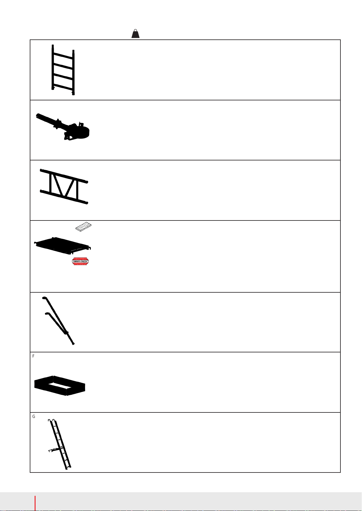
4. Parts
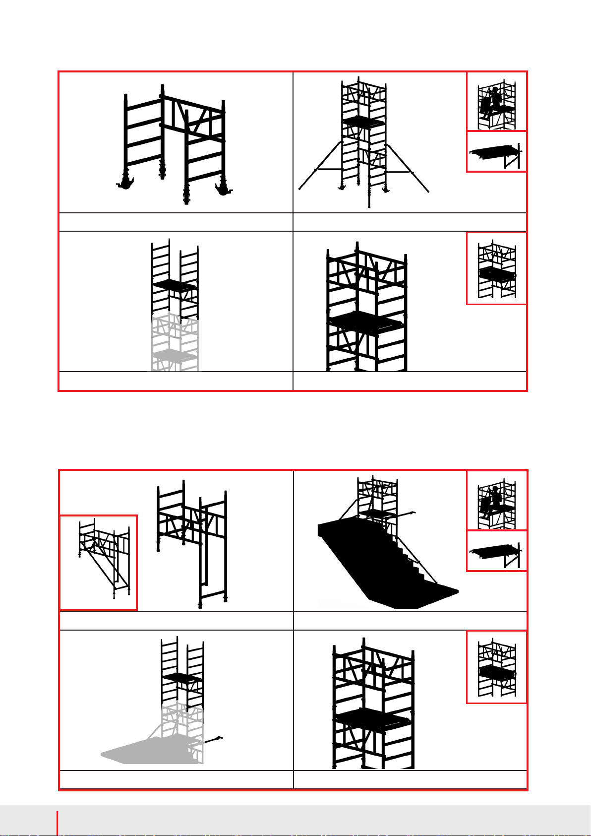
5. Mounting instructions
6. Check before use
7. AssemblingtheMiTOWER/MiTOWER+
8. Assembling the MiTOWER STAIRS
9. Ballast
10. Moving the rolling tower
11. Disassemblyoftherollingtower
12. Inspection,CareandMaintenance
13. Warrantyconditions
14. Abbreviations and logos
Annex
T1. Parts
T2. Mounting instructions
T3.AssemblystepsevenworkingheightsMiTOWER/MiTOWER+
T4.AssemblystepsoddworkingheightsMiTOWER/MiTOWER+
T5.CongurationsMiTOWER
T6.CongurationsMiTOWER+
T7.AssemblystepsMiTOWERSTAIRS
T8.CongurationsMiTOWERSTAIRS
*)4Beaufort:smallbranchesmove,raisesdust
andloosesnow,onalakewavesbecomelonger
withfairlyfrequentwhitehorses.
www.lglt.co.za
Please see Strength & Stability Certificate