Altronic DE-3000+ Series User manual

1
Operating Instructions
DE-3000+ Series Configurable Safety Shutdown and Control System
with Graphing Capabilities
Form DE-3000+ IOI 8-15

DE-3000+ IOI 8-15
All rights reserved © ALTRONIC, LLC 2015 2
1.0 OVERVIEW
1.1 For help locating subjects in this document, a section index is provided on page 68.
A glossary of technical terms begins on page 66.
1.2 The Altronic DE-3000+ controller system is an electronic, microprocessor-based
system designed to sense various analog and digital input points to control and
monitor industrial compressors. The system is field-programmable using a PC
and the supplied terminal program and contains a non-volatile memory to store
the setup. A panel-mounted 10" color MIDAS HMI serves as the user interface.
The DE-3000+ provides for both the safety shutdown functions needed to pre-
vent unnecessary damage to remotely-operated equipment and the closed-loop
automatic control functions needed to optimize their efficiency of operation.
The DE-3000+ also provides for remote data acquisition and supervisory con-
trol in a compact, low cost package for industrial compressor applications. The
optimization strategies available for the management of compressor throughput
include automatic prime mover speed setting as well as capacity control. On
rotary screw compressors, capacity control can be done via suction throttling,
or using an internal gas bypass technique employing poppet valves, turn valves
or slide valves. On reciprocating compressors, capacity can be controlled us-
ing external gas bypass loops or pressure regulation techniques. A wide range
of output options, including both analog current loops and digital outputs, are
provided to interface with the large variety of actuation systems currently in use.
In addition, automatic load limiting based upon prime mover power capabilities
or other application specific limitations, such as cooling capacity, are readily
implemented. There are also AUTO START and OEM ENGINE CONTROL options
that are enabled using the terminal program.
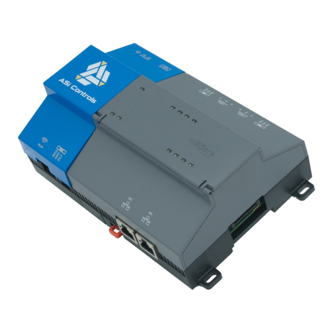
1.3 The DE-3000+ has four components: 10" color MIDAS HMI (G10S0000),
computer module (DE-3000+), terminal module (691171-1), and power supply
module (691122-1). The MIDAS HMI and the computer module communicate
via the Ethernet port using a CAT 5e cable. The computer module connects to
the terminal module via a DB-25 cable. An additional terminal board may be
added for 30 extra channels (691171-2) or 15 extra channels (691175-2). This
increases the channel selections from 1-30 to 1-60 or 1-45 respectively.
To download the terminal program, a DB-9 cable must be connected to the to
the DE-3000+.
2.0 10"COLOR MIDAS HMI
2.1 The 10" color MIDAS HMI serves as the user interface for the DE-3000+ sys-
tem. It is a VGA color standard touchscreen (640 x 480) outdoor model. The
MIDAS HMI has one 10/100 Base-TX Ethernet Port and three fully isolated Se-
rial Communication Ports (two RS-232 and one RS-422/485). In addition, the
MIDAS HMI has one USB Type B Port and two High-retention USB Host Ports.
WARNING: THE CONTROLLER SYSTEM
MUST BE CONFIGURED PRIOR TO USE
ON A COMPRESSOR SYSTEM. REFER-
ENCE THE PROGRAMMING INSTRUC-
TIONS (PAGE 43) FOR INSTRUCTIONS
DESCRIBING HOW TO CONFIGURE THE
CONTROLLER FOR THE SPECIFIC AP-
PLICATION. VERIFY THE PROGRAM IN
NONVOLATILE MEMORY (THE EEPROM)
PRIOR TO STARTING THE SYSTEM.
WARNING: DEVIATION FROM THESE
INSTRUCTIONS MAY LEAD TO IMPROP-
ER ENGINE OPERATION WHICH COULD
CAUSE PERSONAL INJURY TO OPERA-
TORS OR OTHER NEARBY PERSONNEL.
NOTE: THE DE-3000+ REQUIRES
TWO 10-32VDC, 0.2A (MAX) POWER
SOURCES, ONE FOR THE POWER SUP-
PLY BOARD AND THE OTHER FOR THE
COMPUTER MODULE.
TYPE B
USB
STATUS
USB HOST
STATUS
PORT B
PORT A
COMM
RTS (PIN 6)
Tx
CTS (PIN 1)
Rx
COMM
RTS (PIN 6)
Rx
COMM
Tx
COMM
CTS (PIN 1)
(NIC)
ETHERNET
RxB
TxA (PIN 8)
COMM
TxB
TxEN
TxB (PIN 1)
RxA
TxA
AUXILIARY
ETHERNET
(NIC)
COMMS PORTPGM PORT COMMS PORT
RS232 RS485 RS232
DEVICE
USBPOWER
-+USB HOST PORT A (PGM)
ETHERNET RS232 RS232
PORT BPORT A
RS485
AUXILIARY
ETHERNET
POWER
CHASSIS
COMMON
+DC VOLTAGE
1
2
3
CONNECTOR
[OPTIONAL]

DE-3000+ IOI 8-15
All rights reserved © ALTRONIC, LLC 2015 3
2.2 The MIDAS HMI available with the DE-3000+ system uses a status strip to
display the controller status on top of all the screens. The 10 inch screen dis-
plays colored trends for analog values and temperatures, and bar graphs for all
the PIDs. In addition, log files can be stored on the SD card, if mounted on the
MIDAS HMI.
2.3 The MIDAS HMI communicates with the DE-3000+ computer module through
the Modbus TCP/IP protocol. The DE-3000+ computer module has to be cor-
rectly configured to establish communication with the MIDAS HMI.
3.0 COMPUTER MODULE (DE-3000+)
3.1 The Computer Module is designed to be rail-mounted and is the interface be-
tween the Terminal and 10" MIDAS HMI and to other systems. It typically plugs
directly into the Terminal Module using the DB-25 connectors and is held to-
gether with screws and screw locks.
3.2 The computer module must be supplied with 10-32VDC, .2A Max current.
3.2 The computer module comes with a default IP address of 10.1.100.100. In
order to configure the DE-3000+, connect it to a computer through the CAT 5e
cable and type in the default IP address on the web browser. The Home page
appears. User can navigate to the Network Settings and Port Settings by click-
ing on the menu on the left of the web page.

DE-3000+ IOI 8-15
All rights reserved © ALTRONIC, LLC 2015 4
3.3 The Home page gives an overview of the DE-3000+ status. The Status shows
the active time for the computer module along with the firmware and web-
page version.
3.4 The Network Settings page displays the communication configuration of the DE-
3000+. This is the page where the user can change the IP configuration of the
system to match their network. To change the IP configuration, type in the new IP
settings under “Change Settings to:” and press “Apply.” The web page will reload.
Reboot the computer module and access the web browser again. The new IP set-
tings should have been accepted by the computer module.
3.5 The Serial Port Settings page displays the serial port configuration of the DE-
3000+. The settings shown below under “Current” is the default setting and
should be kept this way for optimum communication with the DE-3000+ termi-
nal board(s).

DE-3000+ IOI 8-15
All rights reserved © ALTRONIC, LLC 2015 5
4.0 POWER SUPPLY MODULE
4.1 The Power Supply Module accepts up to four industry-standard, commercial-
ly-available 0.6 inch plug-in Output Modules. The Output Modules provide a
means of using the DE-3000+ Controller Safety Shutdown System status to
interface with other systems on the engine/motor and compressor. A typical
application would be as a relay or solenoid coil driver. The Output Modules are
optically isolated, solid-state switches which are isolated from power supply mi-
nus and engine ground. The Output Modules will be in the open (de-energized)
condition when the unit is not powered.
4.2 Outputs 1 and 2 can be software-configured for either normally-open (N/O) or
normally-closed (N/C) operation and have an LED indicator associated with them.
Outputs 3 and 4 are pre-programmed normally-open for use with the optional
OEM Engine Control or Auto start feature. If an Output Module is programmed for
normally-closed (energized for run), the LED will be ON in the normal run condi-
tion and OFF for a fault condition. For Normally-open configured modules the LED
will be OFF for normal run condition and turn ON for a fault condition.
4.3 The standard Output Module outputs use the top row of the dual 16-position
terminal strip which is marked OUT 1 through OUT 4. Each of these outputs
are fused with a replaceable 6.3 amp slow-blow fuse, Altronic P/N 601653.
In addition to accepting industry-standard Output Modules, a custom Altronic
Output Module P/N 691124 is available for tripping ignition powered CD fuel
valves and shorting CD ignition shutdown leads upon a fault. When making use
of OEM Engine Control, outputs 1 and 2 will not be wired to trip the fuel and ig-
nition valves. When both functions are required, two of these modules are used
as follows: OUT 1 slot must be used to trip the fuel valve, and OUT 2 slot must
be used to short the ignition. If 12-24Vdc is lost to the DE-3000+ annunciator
system, the custom Output Modules will trip the fuel valve and short the igni-
tion shutdown lead. This mimics the “fail-safe” operation of a normally-closed
Output Module and therefore the LED will be ON in the normal run condition
and OFF for a fault condition. In programming the system, these modules are
identified by using the IGN/FUEL selection. Terminals IGN+ and IGN− are used
to connect the shutdown lead, and FV1 and FV2 are used for the CD fuel valve.
A capacitor is included in the Power Supply Module to supply the energy to trip
the fuel valve.
4.4 The 12-24Vdc power for the DE-3000+ system is applied to the power supply
terminals marked (+) and (−) 12–24Vdc INPUT POWER. A 6.3 amp replaceable
slow-blow fuse protects the system from over-currents, and a power LED lights
when power is applied to the system.
4.5 The external connection for the two serial RS-485 communication ports is on
the Power Supply Module terminal strips. Port 2 is for RS-485 serial com-
munication to future Altronic instruments, and port 3 communicates internally
between two different boards within the computer module. Nothing should be
plugged into ports 2 and 3 for normal operations.
4.6 Terminals marked IGN IN and PU IN are used by the DE-3000+ system to de-
tect either engine rotation or ignition system firings. This input monitors chang-
ing signals such as those seen on either the ignition shutdown lead or a mag-
netic pickup monitoring an engine mounted gear.
THE MAGNETIC PICKUP INPUT MUST BE USED FOR APPLICATIONS EN-
ABLING THE AUTO START OR OEM ENGINE CONTROL FUNCTION.
•The IGN IN terminal connects to the positive (+) C.D. ignition shutdown lead.
•The PU IN terminal connects to one magnetic pickup input; the other pickup
wire connects to the minus (−) terminal on the Power Supply Module.
NOTE: AN INSTALLATION MAY USE ONLY
ONE OF THE TERMINALS IGN IN, PU IN,
OR T+.

DE-3000+ IOI 8-15
All rights reserved © ALTRONIC, LLC 2015 6
5.0 TERMINAL MODULE
5.1 The Terminal Module is made to be rail-mounted and is the point of interface
between the field sensor wiring and the DE-3000+ control system. A removable
dual terminal strip is used for the connection of the system to the equipment
mounted discrete sensors which may consist of up to 30 inputs, where any of
the 30 can be used for either a normally-open, normally-closed switch, or analog
inputs including K- or J-type thermocouples. These are listed as channels 01–
30 for the 691171-1 terminal board. They accept industry-standard transducer
signals in the range of 0-5 VDC. Connections from the Terminal Module to the
Display Module are made using the 693115-x series Cable Assembly.
5.2 The DE-3000+ is designed to operate with industry-standard voltage or current-
amplified output transducers in the range of 0 to 5Vdc or 0 to 25mA. Four se-
ries of transducers are available from Altronic: pressure transducers 691201-x,
691204-x and temperature transducers 691202/203-300, 691212/213-450.
5.3 Another terminal board assembly may be added to increase the inputs from 30
to either 45 or 60 inputs. Use cable 693133-1 to connect the two boards. The
691175-2 provides an additional 15 inputs, 4 digital outputs, 2 analog outputs
and an extra speed (pickup) input. The 691171-2 provides an additional 30
inputs, 8 digital outputs, 2 analog outputs, and an extra speed (pickup) input.
5.4 PRESSURE TRANSDUCERS
The pressure transducers, Altronic P/N 691201-x and P/N 691204-x, are pack-
aged in a rugged sealed case with a NPT pressure port, a corrosion resistant
media cavity, and a Packard Electric Metri-Pack connector. The ranges available
are 0-100, 300, 500, 1000, 2000, and 5000 PSIG for the 691201-x series
and 0-50,100, 300, 500 PSIA for the 691204-x series, all of which have an
overload rating of 1.5 times full scale without damage. The three wires from the
transducer are: +5 volt excitation, +0.5 to 4.5 volt output, and minus return.
These three wires connect directly to the back of the Terminal Module using
cable assembly P/N 693008-x.
5.5 DIFFERENTIAL MEASUREMENTS
Differential pressures or temperatures may be measured by using two consecu-
tive channels. The transducers used to measure differential values must be of
the exact same type and range. The first channel of the pair will display the
basic parameter it is monitoring and the second channel of the pair will display
the numeric difference in engineering units of its value subtracted from the first
channel’s value. Setpoints for each channel monitor the displayed value of that
channel. The second channel setpoints monitor the differential value.
5.6 TEMPERATURE TRANSDUCER
The temperature transducers, Altronic P/N 691202-300, 691203-300 with a tem-
perature measurement range of +5 to 300°F and the 691212-450, 691213-450
with a temperature range of -40 to +450°F are packaged in a sealed, stainless steel
housing with a 5/8"-18 UNF threaded body, and a Packard Electric Metri-Pack
connector. During configuration the standard calibration for the 691202/203-300
sensor is selected as dEG1 and the standard calibration for the 691212/213-450 is
selected by choosing dEG2. The three wires from the transducer are: +5 volt excita-
tion, temperature output voltage, and minus return. These wires connect directly to
the Terminal Module using cable assembly P/N 693008-x.
5.7 THERMOCOUPLE INPUTS
The Terminal Modules can accept industry-standard type J or K thermocouples
on inputs 01–60. Automatic cold junction compensation is built-in. The units
can be configured to °F or °C. Both a high and low setpoint is associated with
each channel. The monitor can read type J thermocouples between -76°F and
+1382°F (-60°C and +750°C) and type K thermocouples between -76°F and
+1472°F (-60°C and +800°C).
5.8 N/O and N/C INPUTS
The inputs can also accept standard normally-open and normally- closed con-
tacts. For normally-open input, place the wire between the corresponding in-
puts. Ground the connection to cause a fault. Similarly, for normally-open, wire
the sensor in a normally-closed connection and open it to cause a fault.
691171-1 FOR CHANNELS 01-30
691171-2 FOR CHANNELS 31-60
691175-2 FOR CHANNELS 31-45

DE-3000+ IOI 8-15
All rights reserved © ALTRONIC, LLC 2015 7
5.9 4-20mA inputs
The terminal module can accept 4-20mA inputs by selecting the internally-
connected 200-ohm resistors, creating a termination voltage of .8 to 4.0 volts.
The jumper wires between the + and – terminals for that channel must be con-
nected for proper operation.
5.10 For each input, the corresponding CHANNEL SWITCH must be set according
to the input type. Switches are turned ON by moving them toward the ANALOG
OUT labeling.
5.11 Digital outputs 1 through 8 are pilot-duty, and turn on to common ground when
closed. Outputs 1 through 8 are rated at 500mA, 60V. See FIG. 8 for wiring details.
6.0 MOUNTING
6.1 10" COLOR MIDAS HMI
The operator interface is designed for through-panel mounting. Four VESA mount
tapped screw-holes (M4 x 0.7, 5 mm deep) are present on the rear of the panel to
allow for stand or wall mounting. Care should be taken to remove any loose material
from the mounting cut-out to prevent that material from falling into the operator in-
terface during installation. A gasket is provided to enable sealing to NEMA 4X/IP66
specification. Install the mounting clips provided and tighten to 6.0 pound-force
inch (96 ounce-force inch) evenly for uniform gasket compression.
6.2 POWER SUPPLY MODULE
Mount the Power Supply Module in the panel either on the bottom or the side of
the main panel. The Power Supply Module is made to be rail-mounted onto com-
mercially available 32 or 35mm DIN mounting rails. It is also made to plug directly
into the Terminal Module using the DB-25 connectors and is held together with
screws and screw locks. Two end brackets P/N 604199 should be used to keep
the modules from sliding off the ends of the mounting rail.
Alternatively, the Power Supply Module and the Terminal Module can be mount-
ed separate from each other on the DIN mounting rails but in the same panel;
in this case, a DB-25 male/female cable such as P/N 693115-1 is used to elec-
trically connect these modules. The operating temperature range of the Power
Supply Module is −31°F to +176°F (−35°C to +80°C).
6.3 TERMINAL MODULE
Mount the Terminal Module either on the bottom or the side of the main panel.
The Terminal Module and Power Supply Module can be rail-mounted onto com-
mercially available 32 or 35mm DIN mounting rails. The Terminal Module plugs
directly into the Power Supply Module using the DB-25 D-Sub connectors and
is held together with screws and screw locks. Two end brackets P/N 604199
are used to keep the modules from sliding off the ends of the rail. The Terminal
Module and the Display Module are electrically connected with a DB-25 male/
female cable, 693115-x series or equivalent. The operating temperature range
of the Terminal Module is −31°F to +176°F (−35°C to +80°C).
6.4 PRESSURE TRANSDUCER
Mount the pressure transducer in the panel or in a manifold or tube off of the
engine. Do not expose the pressure transducer to temperatures above 221°F
(105°C). The second terminal module should be placed close to the first and the
wire connecting them should be free of high-powered panel signals.
NOTE: FOR HAZARDOUS LOCATION
INSTALLATION, THIS DEVICE MUST BE
MOUNTED IN A SUITABLE DUST TIGHT
END-ENCLOSURE AND MUST BE WIRED
USING DIVISION 2 WIRING METHODS AS
SPECIFIED IN ARTICLE 501-4 (B), 502-4
(B), AND 503-3 (B) OF THE NATIONAL
ELECTRICAL CODE, NFPA 70 FOR INSTAL-
LATION WITHIN THE UNITED STATES, OR
AS SPECIFIED IN SECTION 19-152 OF
CANADIAN ELECTRICAL CODE FOR INSTAL-
LATION IN CANADA.
IMPORTANT: PRESSURE TRANSDUCERS
WILL WITHSTAND OVERLOADS AS HIGH
AS 1.5 TIMES RATED PRESSURE. IF THE
OVERLOAD RATING IS EXCEEDED, FAIL-
URE MAY OCCUR. PRESSURE FLUCTUA-
TIONS OCCUR IN MOST RECIPROCATING
SYSTEMS; PICK THE TRANSDUCER
WITH A RATING HIGH ENOUGH TO PRE-
VENT OVERLOAD BY PEAK PRESSURES
OF PULSATIONS. IT IS RECOMMENDED
THAT A PRESSURE SNUBBER BE USED
WHICH WILL REDUCE THE PEAK PRES-
SURE APPLIED TO THE TRANSDUCER.
THE LIFE OF THE TRANSDUCER WILL BE
EXTENDED WITH THE USE OF A SNUB-
BER OR PULSATION DAMPENER.

DE-3000+ IOI 8-15
All rights reserved © ALTRONIC, LLC 2015 8
6.5 TEMPERATURE TRANSDUCER
Mount the temperature transducer in a thermowell on the engine or machine.
The actual sensor is located at the bottom of the transducer body; to ensure
accuracy, the tip of the probe should be surrounded by the measured media.
7.0 WIRING (SEE WIRING DIAGRAMS)
7.1 SYSTEM COMPONENT WIRING
A DB-25 male/female cable, 693115-x series or equivalent, is used to connect
the Terminal Module to the Computer Module and secured with the cable lock
screws. If mounted on the same mounting rail, plug the Terminal Module directly
into the Power Supply Module using the DB-25 D-Sub connectors at the ends
of the modules and secure them together with the screws and screw locks cap-
tive to the connectors. If the Power Supply Module and the Terminal Module are
mounted separate from each other (must be mounted in the same panel) a DB-25
male/female cable such as P/N 693115-1 or equivalent is used to connect these
modules. The HMI connects to the computer module through a CAT E5 cable.
7.2 Connect the supply power wires to the 10-32V input power terminals on the
computer board. Connect the ‘+’ to the ‘DC+’ and connect the ‘-’ to the ‘DC-’
input. Do not connect any other wires into the green Phoenix module. The power
rating for the computer module is 10-32V, .2A Max.
7.2 POWER SUPPLY WIRING
Connect the supply power wires to the 12-24Vdc input power terminals on the
power supply, plus to terminal (+) and minus to terminal (−); power requirement
is 12 to 24Vdc (10 watts max.). The DC− terminal must be connected to panel
ground which should be the same as engine ground.
This is the return path for normally-open sensors and MUST be connected for
proper operation. DO NOT ground this device directly to the ignition system
common coil ground.
7.3 CONNECTING THE 10" MIDAS HMI TO EARTH GROUND
The third pin of the power connector is chassis ground for the unit. The unit
should be connected to earth ground (protective earth).
The chassis ground is not connected to signal common of the unit. Maintaining
isolation between earth ground and signal common is not required to operate
the unit. But, other equipment connected to this unit may require isolation be-
tween signal common and earth ground. To maintain isolation between signal
common and earth ground, care must be taken when connections are made. For
example, a power supply with isolation between its signal common and earth
ground must be used. Also, plugging in a USB cable may connect signal com-
mon and earth ground. The USB’s shield may be connected to earth ground at
the host. USB’s shield, in turn, may also be connected to signal common.
7.4 10" MIDAS HMI POWER SUPPLY REQUIREMENTS
The MIDAS HMI panel requires a 24 VDC power supply. The unit may draw con-
siderably less than the maximum rated power depending upon the features be-
ing used. As additional features are used the unit will draw increasing amounts
of power. Items that could cause increases in current are modules, additional
on-board communications, SD card, and other programmed features.
In any case, it is very important that the power supply is mounted correctly if the
unit is to operate reliably. Please take care to observe the following points:
•The power supply must be mounted close to the unit, with usually not
more than 6 feet (1.8 m) of cable between the supply and the operator
interface. Ideally, the shortest length possible should be used.
•The wire used to connect the operator interface’s power supply should
be at least 22-gage wire suitably rated for the temperatures of the
environment to which it is being installed. If a longer cable run is used,
a heavier gage wire should be used. The routing of the cable should be
kept away from large contactors, inverters, and other devices which may
generate significant electrical noise.
IMPORTANT: DO NOT EXCEED THE
ABSOLUTE MAXIMUM RATING OF THE
TRANSDUCERS, 350°F (176°C) FOR THE
691202/203-300 OR 450°F (232°C) FOR
THE 691212/213- 450. CARE SHOULD
BE TAKEN TO PROTECT THE WIRING AND
CONNECTORS FROM CONTACT WITH HOT
SURFACES.

DE-3000+ IOI 8-15
All rights reserved © ALTRONIC, LLC 2015 9
•A power supply with an NEC Class 2 or Limited Power Source (LPS) and
SELV rating is to be used. This type of power supply provides isolation to
accessible circuits from hazardous voltage levels generated by a mains
power supply due to single faults. SELV is an acronym for “safety extra-
low voltage.” Safety extra-low voltage circuits shall exhibit voltages safe
to touch both under normal operating conditions and after a single fault,
such as a breakdown of a layer of basic insulation or after the failure of
a single component has occurred. A suitable disconnect device shall be
provided by the end user.
7.5 SENSOR WIRING DISCRETE INPUTS
The sensor leads connect to the removable terminal strips on the Terminal Mod-
ule. The terminal numbers correspond to the display numbers which also have a
user assigned 20-character label associated with it. The sensor inputs are num-
bered 01-30, 01-45 or 01-60. With AUTO START enabled, the Remote Reset
on the terminal board is wired for a start switch. Sensor inputs 01–60 can be
configured as class A, class B or class C logic. Any discrete sensor point can be
wired for normally-open or normally-closed operation.
•Normally-open (N/O) sensor switches are wired with one wire to the
bottom terminal strip of the respective sensor number and the other to
engine ground which should be the same as power minus (−). A short
jumper from the bottom terminal to the top terminal must be connected
for normally-open sensors. (See wiring diagrams)
•Normally-closed (N/C) sensor switches are wired with one wire to the bot-
tom terminal strip and the other to the top terminal strip of the respective
sensor number. Note that the short jumper wire must be removed.
•Remote stop and remote reset are wired the same as the sensor
switches, and can be used with either normally-open or normally-closed
contacts.
Use a wire size between 16 AWG (max.) and 24 AWG (min.) to connect the sen-
sor switches to the terminal strip connector. Strip the insulation back 3/8"; twist
the exposed wires tightly together. Insert the exposed wire completely into the
terminal strip and securely tighten the clamping screw. Wires running to sensor
switches must be in good condition or replaced with new wires. When running
wires, take care not to damage the insulation and take precautions against later
damage from vibration, abrasion, or liquids in conduits. An explosion-proof con-
duit is not required. However; wires should be protected from damage by run-
ning them in a protective conduit or in sheaths where appropriate. In addition, it
is essential that the following practices be adhered to:
A. Never run sensor wires in the same conduit with ignition wiring or other
high energy wiring such as the AC line power.
B. Keep secondary wires to spark plugs and other high voltage wiring at
least eight inches (200mm) away from sensor and sensor wiring.
C. Sensor switches may be connected to any passive device using contacts
such as standard switch gauges, pressure or level switches. DO NOT con-
nect sensor leads to any voltage producing element.
D. In the case of a field conversion, where sensors have previously been
used with Murphy tattletales, it is recommended that the sensors be
checked frequently when the DE system is first put into use. Sensor
contacts may be burned or pitted from past exposure to ignition system
primary voltage. It is advisable to replace such sensors.
E. If it becomes necessary to check sensor switch to panel wiring with an
ohmmeter or other checker, first DISCONNECT the plug-in terminal strips
from the Terminal Module. Applying voltage to the DE-3000+ system
through the sensor leads may damage the device. The area should be
tested as non-hazardous before such testing commences.

DE-3000+ IOI 8-15
All rights reserved © ALTRONIC, LLC 2015 10
ANALOG SENSOR WIRING
For each analog monitored point, inputs 01–60, select a transducer - either an
Altronic pressure or temperature transducer listed above or one that outputs a
signal in the range of 0 to 5 Vdc or 0 to 25 mA. Mount as described above. Use
cable assembly 693008-x or similar to wire transducer to the Terminal Module.
An internal 5 volt sensor supply (500 mA. max.) is available to power the Altronic
transducers; See wiring diagrams. If the 5 volt sensor supply exits the panel, it
must be fused with a 0.5 ampere fuse. If 24Vdc powered sensors are used, the
24 volt supply to them must be fused appropriately. Take care not to damage the
insulation when installing and take precautions against later damage from vibra-
tion, abrasion, or liquids in conduits. In addition, it is essential that the following
practices be adhered to:
A. Never run sensor wires in the same conduit with ignition wiring or other
high energy wiring such as AC line power.
B. Keep secondary wires to spark plugs and other high voltage wiring at
least eight inches (200mm) away from sensor and sensor wiring.
7.6 THERMOCOUPLES AND THERMOCOUPLE EXTENSION WIRE
Grounded or ungrounded type J or K thermocouples may be used. Use thermo-
couple extension wire of the same type as the thermocouple probe to connect to
the terminal module. Use stranded thermocouple wire having a moisture-resis-
tant insulation such as PVC; for higher ambient temperatures, Teflon or B-fibre
insulated thermocouple wire is recommended. To ensure that an accurate signal
is transmitted to the device, avoid any added junctions, splices and contact with
other metals. On unused channels, leave the small jumper wire supplied with the
system in place. Take care not to damage the insulation when installing and take
precautions against later damage from vibration, abrasion, or liquids in conduits.
In addition, it is essential that the following practices be adhered to:
A. Never run sensor wires in the same conduit with ignition wiring or other
high energy wiring such as AC line power.
B. Keep secondary wires to spark plugs and other high voltage wiring at
least eight inches (200mm) away from sensor and sensor wiring.
7.7 LUBE/NO-FLOW SENSOR:
Channels 27 and 28 may be used for a lube/no-flow proximity cycle switch as
an option. Wire the sensor according to section 5.8. The Sensor may be wired
as either a N/O or a N/C with a jumper. The DIP switches on the terminal board
must be set as an analog configuration. The lube/no-flow channels generate a
fault when the time between pulses exceeds the programmed run pulse time.
7.8 OUTPUT SWITCH WIRING
The Power Supply Module accepts an industry-standard 0.6" Output Module.
The following modules are available from Altronic:
691124 This custom module has two uses: connection to a Murphy fuel valve
and directly grounding a C.D. ignition system.
A. Use in position OUT 1 to connect to a C.D. ignition-type Murphy
fuel valve. Connect terminals 3 and 8 of the fuel valve to the
Power Supply Module terminals marked F1 (FV1) and F2 (FV2).
B. Use in position OUT 2 to directly ground-out (stop) a C.D. ignition
system. Wire the C.D. ignition shutdown lead and ignition ground
to the Power Supply Module terminals marked I+ (IGN+) and I-
(IGN-) observing the proper polarity for the ignition system.
DO NOT connect directly to the ignition system common coil ground.
691125 This module is rated for 5-48 Vdc, 5.0 A., and may be used in any of
the four output slots OUT 1 through OUT 4. It may be used to inter-
rupt the DC supply to DC-powered ignition systems such as Altronic
CD1, CPU-90, II-CPU or DISN.
691056 This module is rated for 5-60 Vdc, 2.0 A., and may be used in any of
the four output slots OUT 1 through OUT 4.
NOTE: ADDITIONAL CHANNEL SET UP WILL
BE REQUIRED IN THE TERMINAL SOFT-
WARE PROGRAM.

DE-3000+ IOI 8-15
All rights reserved © ALTRONIC, LLC 2015 11
691066 This module is rated for 5-200 Vdc, 0.67 A. and may be used in any
of the four output slots OUT 1 through OUT 4.
691065 This module is rated for 24-280 Vac, 2.0 A. and may be used in any
of the four output slots OUT 1 through OUT 4.
7.9 RS-485 COMMUNICATIONS WIRING
•Port 2 is for communication between the display and terminal boards.
•Port 3 is for RS-485 serial communication between the computer mod-
ule and the HMI.
These should not be connected for normal operation.
7.10 SENSE ROTATION INPUT
Terminals marked IGN IN and PU IN on the Power Supply Module are used by
the DE-3000+ system to detect either engine rotation or ignition system firings.
On applications using multiple terminal board assemblies, the T+ terminal on the
second terminal board (the one not directly connected to the power supply) can
be used to add a second RPM value. The T+ input is only for use with magnetic
pickups. This input monitors voltage signals such as those seen on either the igni-
tion shutdown lead or a magnetic pickup monitoring an engine-mounted gear.
•The IGN IN terminal connects to the positive (+) C.D. ignition shutdown lead.
•The PU IN terminal connects to one magnetic pickup input; the other pickup
wire connects to the minus (−) terminal on the Power Supply Module.
•The T+ terminal connects to one magnetic pickup input; the other pickup
wire connects to the terminal on the terminal module.
THE MAGNETIC PICKUP INPUT MUST BE USED FOR APPLICATIONS ENABLING
THE OPTIONAL AUTO START OR OEM ENGINE CONTROL FUNCTION.
8.0 HAZARDOUS AREA OPERATION
8.1 The DE-3000+ system is CSA-certified for CLASS I, DIVISION 2, GROUPS C
and D areas when mounted in a suitable enclosure.
In addition, the following requirements must be met (refer to NFPA standard no. 493):
•The low voltage sensor switch wires within the panel enclosure must
be kept at least two (2) inches away from other wiring. Run the sensor
switch wires leaving the panel in a separate conduit from all other wiring
and keep them separate
•Wiring to the sensors must have a grade of insulation capable of with-
standing an AC voltage of 500 volts RMS.
•Sensor wires must be run in separate conduits and junction boxes from high
voltage wires such as ignition, fuel valve, and other high voltage wiring.
NOTE: AN INSTALLATION MAY USE ONLY
ONE OF THE TERMINALS IGN IN, PU IN,
OR T+.
WARNING: SUBSTITUTION OF COMPO-
NENTS MAY IMPAIR INTRINSIC SAFETY
AND/OR SUITABILITY FOR CLASS I, DIV.
2, GROUPS C AND D. DO NOT DISCON-
NECT EQUIPMENT IN DIV. 2 ENVIRON-
MENT UNLESS POWER IS SWITCHED
OFF OR THE AREA IS KNOWN TO BE
NON-HAZARDOUS.

DE-3000+ IOI 8-15
All rights reserved © ALTRONIC, LLC 2015 12
9.0 10"MIDAS HMI MAIN MENU
9.1 The 10" MIDAS HMI has three buttons on its bezel. The red triangle directs to
the Alarms page, the horizontal button in the middle directs to the Main Menu
page, and the green home button directs to the Home page.
9.2 The 10" MIDAS HMI screens can be accessed through the Main Menu and MIDAS
HMI Utility screens as shown below. The HMI Utility screen can be accessed by
clicking on the “HMI UTILITY” button on the Main Menu screen.
To return from the HMI Utility screen to Main Menu screen, click on the “MAIN
MENU” button on the HMI Utility screen.
NOTE: THE SCREENS SHOWN IN THIS
SECTION ON THE HMI REFLECT A
GENERAL LAYOUT AND MAY APPEAR
DIFFERENTLY DUE TO DIFFERENCES IN
ENGINE CONFIGURATIONS.
NOTE: THE HORIZONTAL BLUE BUT-
TON IN THE MIDDLE ONLY LIGHTS UP
WHEN THERE IS A MEMORY CARD (SD)
INSERTED IN THE HMI.

DE-3000+ IOI 8-15
All rights reserved © ALTRONIC, LLC 2015 13
9.3 To log-in to the MIDAS HMI, click on the credentials button on the Main Menu
screen. When the Log-in popup appears, the status displays whether the user is
logged in or not. If the “LOGOUT” is selected, click on the “LOGIN” button and
enter the credentials.
Once the credentials are authorized, the “LOGIN” button will be selected show-
ing that the user has successfully been logged in.

DE-3000+ IOI 8-15
All rights reserved © ALTRONIC, LLC 2015 14
9.4 Write control needs to be enabled whenever a value is to be written to the DE-3000+
controller. To be able to enable write control, press on the “CONTROL WRITE” button
on the Main Menu screen.
If the user is not logged in, credentials would be required before accessing the
write control popup. Once the popup appears, press the “WRITE” button to en-
able write control.
The write control should be set to “Read” mode when not editing DE-3000+
controller registers. To avoid the write control from staying at “Write” all the
time, a timer is implemented on the MIDAS HMI that changed the write control
to “Read” mode after it expires. The default value of the timer is set to 120 sec,
but the user can increase it up to 600 sec.

DE-3000+ IOI 8-15
All rights reserved © ALTRONIC, LLC 2015 15
To access the write control timer, press the “WRITE TIMER” button on the HMI Utility.
After the credentials are verified, the write control timer popup appears. The
Control Write Time (in sec) can be modified to increase or decrease the time for
the write feature to expire. The Time Elapsed (in sec) shows how much time is
left before the write control will revert to “Read” mode.

DE-3000+ IOI 8-15
All rights reserved © ALTRONIC, LLC 2015 16
9.5 The Alarms on the DE-3000+ controller are setup and executed through the
MIDAS HMI. There is a two-step alarm activation system in place that needs to
be setup before alarms will become active.
The first step is to enable the alarm on the DE-3000+ system. By default, the
DE-3000+ system have the alarms disabled. To enable, press the “ENABLE
ALARMS” button on the HMI Utility page.
After the credentials are verified, the Alarm Enable/Disable popup screen appears.
Click on the “ENABLE” button to enable the alarms on the DE-3000+ system.

DE-3000+ IOI 8-15
All rights reserved © ALTRONIC, LLC 2015 17
The second step is to enable the High or Low alarm on each channel. This can
be done on the Channel Status page. When the High/Low Alarms are armed, and
the alarm condition is met, the alarms show up as yellow on the data box and the
alarm strip describing the nature of the alarm appears at the bottom of the screen.
9.6 In addition to the Main Menu and HMI Utility screens, all the screens on the
MIDAS HMI can be accessed through the Menu Popup at the bottom of every HMI
screen.

DE-3000+ IOI 8-15
All rights reserved © ALTRONIC, LLC 2015 18
Once the Menu popup is pressed, screen navigation buttons appear at the bot-
tom of the screen. To view more navigation buttons, press the “EXTENDED
MENU” button.
The Menu Popups can be canceled by pressing the red exit button.

DE-3000+ IOI 8-15
All rights reserved © ALTRONIC, LLC 2015 19
9.7 The MIDAS HMI screens can also be navigated through up and down arrow keys
at the bottom of every screen. The blue arrow keys are used to move to the next
or previous category of screens while the maroon arrow keys are used to move to
the next or previous screen.
9.8 The Home Screen can be accessed by clicking on the “HOME” button on the
Main Menu screen. Through the Home screen, the user can control the opera-
tion and monitor the status of the DE-3000+ controller. The screenshot shows
the Home screen for a DE-3000+ system. Home screens may vary based on the
project configuration.

DE-3000+ IOI 8-15
All rights reserved © ALTRONIC, LLC 2015 20
9.9 The START button on the Home screen sends a command to the DE-3000+
controller to start.
9.10 STOP key is used for a manual stop condition. By pressing the STOP key, the
controller activates the configured output modules in the power supply.
Table of contents
Other Altronic Control System manuals
