Altronic DE-3000 User manual

1
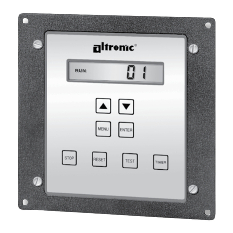
Operating Instructions
DE-3000 Series Configurable Safety Shutdown and Control System
with Graphing Capabilities
Form DE-3000 IOI 7-17
SOME FEATURES IN THIS MANUAL ARE ONLY APPLICABLE TO
DE-3000 FIRMWARE DATED 2014 OR LATER, INCLUDING:
•OEM Engine Control
•Lube No-Flow/Lube Monitoring
•Linear Ramp Control
•Cool-down
•Integrated output timers on digital output channels #5 and #13
•Multi-Start

DE-3000 IOI 7-17
All rights reserved © ALTRONIC, LLC 2017 2
1.0 OVERVIEW
1.1 For help locating subjects in this document, a section index is provided on page 61.
A glossary of technical terms begins on page 58.
1.2 The Altronic DE-3000 controller system is an electronic, microprocessor-based
system designed to sense various analog and digital input points to control and
monitor industrial compressors. The system is field-programmable using a PC
and the supplied terminal program and contains a non-volatile memory to store
the setup. Serial communications provide an interface to PC’s, PLC’s, modems
and satellite uplinks for remote communication. An LCD display shows system
status, programmed engine/motor and compressor parameters and channel la-
bels. A front-mounted keypad serves as the user interface. The DE-3000 pro-
vides for both the safety shutdown functions needed to prevent unnecessary
damage to remotely-operated equipment and the closed-loop automatic control
functions needed to optimize their efficiency of operation. The DE-3000 also
provides for remote data acquisition and supervisory control in a compact, low
cost package for industrial compressor applications. The optimization strate-
gies available for the management of compressor throughput include automatic
prime mover speed setting as well as capacity control. On rotary screw compres-
sors, capacity control can be done via suction throttling, or using an internal
gas bypass technique employing poppet valves, turn valves or slide valves. On
reciprocating compressors, capacity can be controlled using external gas bypass
loops or pressure regulation techniques. A wide range of output options, includ-
ing both analog current loops and digital outputs, are provided to interface with
the large variety of actuation systems currently in use. In addition, automatic
load limiting based upon prime mover power capabilities or other application
specific limitations, such as cooling capacity, are readily implemented. There
are also AUTO START and OEM ENGINE CONTROL options that are enabled
using the terminal program.
1.3 The system has three main parts: a panel-mounted Display Module (DE-3000),
a Power Supply Module (691122-1), and a Terminal Module (691171-1). These
components are interconnected by means of Cable assembly (693115-1). An
additional terminal board may be added for 30 extra channels (691171-2) or 15
extra channels (691175-2). This increases the channel selections from 1-30 to
1-60 or 1-45 respectively.
2.0 DISPLAY MODULE
2.1 The Display Module serves as the user interface for the DE-3000 system. It is in
a 6.5" x 6.5" panel-mounted enclosure and consists of an alphanumeric backlit
LCD display, a 16-key front-mounted keypad, DB-25 D-Sub and DB-9 D-Sub
connectors and five pairs of serial port indicators.
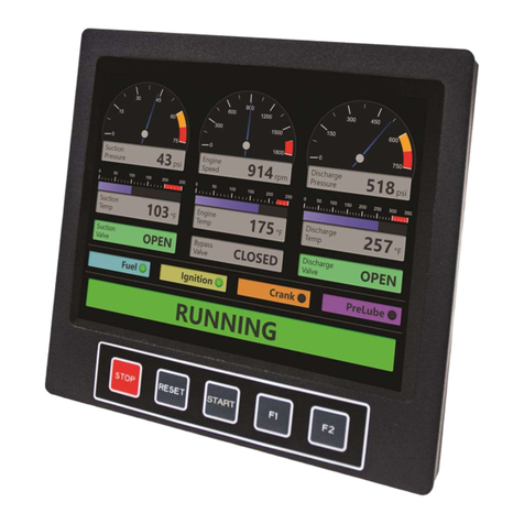
Two DE-3000 models are available and their displays are compatible with each
other, although they have a few functional differences. The ‘classic’ display is
4x20 characters, and the “new” display features 128x64 multi-color graph-
ics. The larger display uses the top line to further annunciate the engine status
“RUNNING, TIMERS ACTIVE, FIRST FAULT,” etc. The home screen, typical of
the 4x20 display, appears at the bottom of the larger display. It also incorpo-
rates a graphing capability which replaces the original bargraph feature. Color
backlighting has been added to the new display. The backlight color changes,
e.g., green for RUNNING, yellow for TIMERS ACTIVE and red for STOP/FAULT
condition, to indicate the status of the machine.
2.2 The keypad is a sealed membrane unit that contains the familiar STOP, RESET
and TEST keys as well as other keys used to navigate through channel status and
description, view process screens, and to edit the configuration.
2.3 The LCD displays a HOME SCREEN that displays a status line, the speed, the
suction pressure and the discharge pressure. Pressing the VIEW CHANNEL key
displays the channel number, its timer status, analog value (if applicable) and
the corresponding 20-character user defined label.
NOTE: IF POSSIBLE, KEEP THE ORIGI-
NAL SHIPPING CONTAINER. IF FUTURE
TRANSPORTATION OR STORAGE OF THE
CONTROLLER IS NECESSARY, THIS CON-
TAINER WILL PROVIDE THE OPTIMUM
PROTECTION.
WARNING: THE CONTROLLER SYSTEM
MUST BE CONFIGURED PRIOR TO USE
ON A COMPRESSOR SYSTEM. REFER-
ENCE THE PROGRAMMING INSTRUC-
TIONS (PAGE 53) FOR INSTRUCTIONS
DESCRIBING HOW TO CONFIGURE THE
CONTROLLER FOR THE SPECIFIC AP-
PLICATION. VERIFY THE PROGRAM IN
NONVOLATILE MEMORY (THE EEPROM)
PRIOR TO STARTING THE SYSTEM. RE-
FER TO SECTION 10.0 ON HOW TO VIEW
THE CURRENT CONFIGURATION.
WARNING: DEVIATION FROM THESE
INSTRUCTIONS MAY LEAD TO IMPROP-
ER ENGINE OPERATION WHICH COULD
CAUSE PERSONAL INJURY TO OPERA-
TORS OR OTHER NEARBY PERSONNEL.

DE-3000 IOI 7-17
All rights reserved © ALTRONIC, LLC 2017 3
2.4 The keypad, along with the LCD display, are used to navigate through channel
status and descriptions, view process screens, and to view or edit the system’s
configuration. The ↑UNITS or ↓UNITS or the →TENS or ←TENS keys are used
to access channels by increasing or decreasing the channel numbers by one or
by ten with each key press. Pressing the NEXT key advances the display to the
next screen or item. All menu adjustments are saved in non-volatile EEPROM
memory by pressing the ENTER key. The EEPROM memory retains the current
configuration during normal operation, after compressor shutdown and a system
power-down.
2.5 Five pairs of LED’s are provided on the back of the Display Module for trouble-
shooting purposes, one Receive (RX) and one Transmit (TX) LED for each port.
The TX LED will flash when the Display Module is transmitting serial communi-
cations on the labeled port. The RX LED will flash when the Display Module is
receiving serial communications on the labeled port.
2.6 Ports 4 and 5 are located on the display board.
3.0 POWER SUPPLY MODULE
3.1 The Power Supply Module is made to be rail-mounted and is the interface be-
tween the Terminal and Display Modules and to other systems. It typically plugs
directly into the Terminal Module using the DB-25 connectors and is held to-
gether with screws and screw locks.
3.2 The Power Supply Module accepts up to four industry-standard, commercially-
available 0.6 inch plug-in Output Modules. The Output Modules provide a means
of using the DE-3000 controller safety shutdown system status to interface with
other systems on the engine/motor and compressor. A typical application would
be as a relay or solenoid coil driver. T he Output Modules are optically isolated,
solid-state switches which are isolated from power supply minus and engine
ground. The Output Modules will be in the open (de-energized) condition when
the unit is not powered.
Outputs 1 and 2 can be software-configured for either normally-open (N/O) or
normally-closed (N/C) operation and have an LED indicator associated with them.
Outputs 3 and 4 are pre-programmed normally-open for use with the optional
OEM Engine Control or Auto start feature. If an Output Module is programmed for
normally-closed (energized for run), the LED will be ON in the normal run condi-
tion and OFF for a fault condition. For Normally-open configured modules the LED
will be OFF for normal run condition and turn ON for a fault condition.
The standard Output Module outputs use the top row of the dual 16-position
terminal strip which is marked OUT 1 through OUT 4. Each of these outputs
are fused with a replaceable 6.3 amp slow-blow fuse, Altronic P/N 601653.
In addition to accepting industry-standard Output Modules, a custom Altronic
Output Module P/N 691124 is available for tripping ignition powered CD fuel
valves and shorting CD ignition shutdown leads upon a fault. When making use
of OEM Engine Control, outputs 1 and 2 will not be wired to trip the fuel and ig-
nition valves. When both functions are required, two of these modules are used
as follows: OUT 1 slot must be used to trip the fuel valve, and OUT 2 slot must
be used to short the ignition. If 12-24Vdc is lost to the DE-3000 annunciator
system, the custom Output Modules will trip the fuel valve and short the igni-
tion shutdown lead. This mimics the “fail-safe” operation of a normally-closed
Output Module and therefore the LED will be ON in the normal run condition
and OFF for a fault condition. In programming the system, these modules are
identified by using the IGN/FUEL selection. Terminals IGN+ and IGN− are used
to connect the shutdown lead, and FV1 and FV2 are used for the CD fuel valve.
A capacitor is included in the Power Supply Module to supply the energy to trip
the fuel valve.
3.3 The 12-24Vdc power for the DE-3000 system is applied to the power supply
terminals marked (+) and (−) 12–24Vdc INPUT POWER. A 6.3 amp replaceable
slow-blow fuse protects the system from over-currents, and a power LED lights
when power is applied to the system.
CLASSIC DISPLAY
NEW DISPLAY

DE-3000 IOI 7-17
All rights reserved © ALTRONIC, LLC 2017 4
3.4 The external connection for the two serial RS-485 communication ports is on
the Power Supply Module terminal strips. Port 2 is for RS-485 serial communi-
cation to future Altronic instruments, and port 3 is for RS-485 serial communi-
cation to a PC (personal computer) or a PLC (programmable logic controller) to
perform remote monitoring or control functions if desired.
3.5 Terminals marked IGN IN and PU IN are used by the DE-3000 system to detect
either engine rotation or ignition system firings. This input monitors changing
signals such as those Seen on either the ignition shutdown lead or a magnetic
pickup monitoring an engine mounted gear.
THE MAGNETIC PICKUP INPUT MUST BE USED FOR APPLICATIONS EN-
ABLING THE AUTO START OR OEM ENGINE CONTROL FUNCTION.
•The IGN IN terminal connects to the positive (+) C.D. ignition shutdown lead.
•The PU IN terminal connects to one magnetic pickup input; the other pickup
wire connects to the minus (−) terminal on the Power Supply Module.
4.0 TERMINAL MODULE
4.1 The Terminal Module is made to be rail-mounted and is the point of interface
between the field sensor wiring and the DE-3000 control system. A removable
dual terminal strip is used for the connection of the system to the equipment
mounted discrete sensors which may consist of up to 30 inputs, where any of
the 30 can be used for either a normally-open, normally-closed switch, or analog
inputs including K- or J-type thermocouples. These are listed as channels 01–
30 for the 691171-1 terminal board. They accept industry-standard transducer
signals in the range of 0-5 VDC. Connections from the Terminal Module to the
Display Module are made using the 693115-x series Cable Assembly.
4.2 The DE-3000 is designed to operate with industry-standard voltage or current-
amplified output transducers in the range of 0 to 5Vdc or 0 to 25mA. Four se-
ries of transducers are available from Altronic: pressure transducers 691201-x,
691204-x and temperature transducers 691202/203-300, 691212/213-450.
4.3 Another terminal board assembly may be added to increase the inputs from 30
to either 45 or 60 inputs. Use cable 693133-1 to connect the two boards. The
691175-2 provides an additional 15 inputs, 4 digital outputs, 2 analog outputs
and an extra speed (pickup) input. The 691171-2 provides an additional 30
inputs, 8 digital outputs, 2 analog outputs, and an extra speed (pickup) input.
4.4 PRESSURE TRANSDUCERS
The pressure transducers, Altronic P/N 691201-x and P/N 691204-x, are pack-
aged in a rugged sealed case with a NPT pressure port, a corrosion resistant
media cavity, and a Packard Electric Metri-Pack connector. The ranges available
are 0-100, 300, 500, 1000, 2000, and 5000 PSIG for the 691201-x series
and 0-50,100, 300, 500 PSIA for the 691204-x series, all of which have an
overload rating of 1.5 times full scale without damage. The three wires from the
transducer are: +5 volt excitation, +0.5 to 4.5 volt output, and minus return.
These three wires connect directly to the back of the Terminal Module using
cable assembly P/N 693008-x.
4.5 DIFFERENTIAL MEASUREMENTS
Differential pressures or temperatures may be measured by using two consecu-
tive channels. The transducers used to measure differential values must be of
the exact same type and range. The first channel of the pair will display the
basic parameter it is monitoring and the second channel of the pair will display
the numeric difference in engineering units of its value subtracted from the first
channel’s value. Setpoints for each channel monitor the displayed value of that
channel. The second channel setpoints monitor the differential value.
4.6 TEMPERATURE TRANSDUCER
The temperature transducers, Altronic P/N 691202-300, 691203-300 with a tem-
perature measurement range of +5 to 300°F and the 691212-450, 691213-450
with a temperature range of -40 to +450°F are packaged in a sealed, stainless steel
NOTE: AN INSTALLATION MAY USE ONLY
ONE OF THE TERMINALS IGN IN, PU IN,
OR T+.
691171-1 FOR CHANNELS 01-30
691171-2 FOR CHANNELS 31-60
691175-2 FOR CHANNELS 31-45

DE-3000 IOI 7-17
All rights reserved © ALTRONIC, LLC 2017 5
housing with a 5/8"-18 UNF threaded body, and a Packard Electric Metri-Pack
connector. During configuration the standard calibration for the 691202/203-300
sensor is selected as dEG1 and the standard calibration for the 691212/213-450 is
selected by choosing dEG2. The three wires from the transducer are: +5 volt excita-
tion, temperature output voltage, and minus return. These wires connect directly to
the Terminal Module using cable assembly P/N 693008-x.
4.7 THERMOCOUPLE INPUTS
The Terminal Modules can accept industry-standard type J or K thermocouples
on inputs 01–60. Automatic cold junction compensation is built-in. The units
can be configured to °F or °C. Both a high and low setpoint is associated with
each channel. The monitor can read type J thermocouples between -76°F and
+1382°F (-60°C and +750°C) and type K thermocouples between -76°F and
+1472°F (-60°C and +800°C).
4.8 N/O and N/C INPUTS
The inputs can also accept standard normally-open and normally- closed con-
tacts. For normally-open input, place the wire between the corresponding in-
puts. Ground the connection to cause a fault. Similarly, for normally-open, wire
the sensor in a normally-closed connection and open it to cause a fault.
4.9 4-20mA inputs
The terminal module can accept 4-20mA inputs by selecting the internally-
connected 200-ohm resistors, creating a termination voltage of .8 to 4.0 volts.
The jumper wires between the + and – terminals for that channel must be con-
nected for proper operation.
4.10 For each input, the corresponding CHANNEL SWITCH must be set according
to the input type. Switches are turned ON by moving them toward the ANALOG
OUT labeling.
4.11 Digital outputs 1 through 8 are pilot-duty, and turn on to common ground when
closed. Outputs 1 through 8 are rated at 500mA, 60V. See FIG. 8 for wiring details.
5.0 MOUNTING
5.1 DISPLAY MODULE
Mount the Display Module inside a control panel or to a suitable flat surface so
that the display is at a convenient viewing height. A drilling template and mount-
ing dimensions are provided.
5.2 POWER SUPPLY MODULE
Mount the Power Supply Module in the panel either on the bottom or the side of
the main panel. The Power Supply Module is made to be rail-mounted onto com-
mercially available 32 or 35mm DIN mounting rails. It is also made to plug directly
into the Terminal Module using the DB-25 connectors and is held together with
screws and screw locks. Two end brackets P/N 604199 should be used to keep
the modules from sliding off the ends of the mounting rail.
Alternatively, the Power Supply Module and the Terminal Module can be mount-
ed separate from each other on the DIN mounting rails but in the same panel;
in this case, a DB-25 male/female cable such as P/N 693115-1 is used to elec-
trically connect these modules. The operating temperature range of the Power
Supply Module is −31°F to +176°F (−35°C to +80°C).
5.3 TERMINAL MODULE
Mount the Terminal Module either on the bottom or the side of the main panel.
The Terminal Module and Power Supply Module can be rail-mounted onto com-
mercially available 32 or 35mm DIN mounting rails. The Terminal Module plugs
directly into the Power Supply Module using the DB-25 D-Sub connectors and
is held together with screws and screw locks. Two end brackets P/N 604199
are used to keep the modules from sliding off the ends of the rail. The Terminal
Module and the Display Module are electrically connected with a DB-25 male/
female cable, 693115-x series or equivalent. The operating temperature range
of the Terminal Module is −31°F to +176°F (−35°C to +80°C).
NOTE: AVOID MOUNTING THE UNIT
WITH THE LCD DISPLAY FACING DIRECT
SUNLIGHT. THE DISPLAY OPERATING
TEMPERATURE RANGE IS −13°F TO
+149°F (−25°C TO +65°C).
IMPORTANT: PRESSURE TRANSDUCERS
WILL WITHSTAND OVERLOADS AS HIGH
AS 1.5 TIMES RATED PRESSURE. IF THE
OVERLOAD RATING IS EXCEEDED, FAIL-
URE MAY OCCUR. PRESSURE FLUCTUA-
TIONS OCCUR IN MOST RECIPROCATING
SYSTEMS; PICK THE TRANSDUCER
WITH A RATING HIGH ENOUGH TO PRE-
VENT OVERLOAD BY PEAK PRESSURES
OF PULSATIONS. IT IS RECOMMENDED
THAT A PRESSURE SNUBBER BE USED
WHICH WILL REDUCE THE PEAK PRES-
SURE APPLIED TO THE TRANSDUCER.
THE LIFE OF THE TRANSDUCER WILL BE
EXTENDED WITH THE USE OF A SNUB-
BER OR PULSATION DAMPENER.

DE-3000 IOI 7-17
All rights reserved © ALTRONIC, LLC 2017 6
5.4 PRESSURE TRANSDUCER
Mount the pressure transducer in the panel or in a manifold or tube off of the
engine. Do not expose the pressure transducer to temperatures above 221°F
(105°C). The second terminal module should be placed close to the first and the
wire connecting them should be free of high-powered panel signals.
5.5 TEMPERATURE TRANSDUCER
Mount the temperature transducer in a thermowell on the engine or machine.
The actual sensor is located at the bottom of the transducer body; to ensure
accuracy, the tip of the probe should be surrounded by the measured media.
6.0 WIRING (SEE WIRING DIAGRAMS)
6.1 SYSTEM COMPONENT WIRING
A DB-25 male/female cable, 693115-x series or equivalent, is used to connect
the Terminal Module to the Display Module and secured with the cable lock
screws. If mounted on the same mounting rail, plug the Terminal Module directly
into the Power Supply Module using the DB-25 D-Sub connectors at the ends
of the modules and secure them together with the screws and screw locks cap-
tive to the connectors. If the Power Supply Module and the Terminal Module are
mounted separate from each other (must be mounted in the same panel) a DB-
25 male/female cable such as P/N 693115-1 or equivalent is used to connect
these modules.
6.2 POWER WIRING
Connect the supply power wires to the 12-24Vdc input power terminals on the
power supply, plus to terminal (+) and minus to terminal (−); power requirement
is 12 to 24Vdc (10 watts max.). The DC− terminal must be connected to panel
ground which should be the same as engine ground.
This is the return path for normally-open sensors and MUST be connected for
proper operation. DO NOT ground this device directly to the ignition system
common coil ground.
6.3 SENSOR WIRING DISCRETE INPUTS
The sensor leads connect to the removable terminal strips on the Terminal Mod-
ule. The terminal numbers correspond to the display numbers which also have a
user assigned 20-character label associated with it. The sensor inputs are num-
bered 01-30, 01-45 or 01-60. With AUTO START enabled, the Remote Reset
on the terminal board is wired for a start switch. Sensor inputs 01–60 can be
configured as class A, class B or class C logic. Any discrete sensor point can be
wired for normally-open or normally-closed operation.
•Normally-open (N/O) sensor switches are wired with one wire to the
bottom terminal strip of the respective sensor number and the other to
engine ground which should be the same as power minus (−). A short
jumper from the bottom terminal to the top terminal must be connected
for normally-open sensors. (See wiring diagrams)
•Normally-closed (N/C) sensor switches are wired with one wire to the bot-
tom terminal strip and the other to the top terminal strip of the respective
sensor number. Note that the short jumper wire must be removed.
•Remote stop and remote reset are wired the same as the sensor
switches, and can be used with either normally-open or normally-closed
contacts.
Use a wire size between 16 AWG (max.) and 24 AWG (min.) to connect the sen-
sor switches to the terminal strip connector. Strip the insulation back 3/8"; twist
the exposed wires tightly together. Insert the exposed wire completely into the
terminal strip and securely tighten the clamping screw. Wires running to sensor
switches must be in good condition or replaced with new wires. When running
wires, take care not to damage the insulation and take precautions against later
damage from vibration, abrasion, or liquids in conduits. An explosion-proof con-
duit is not required. However; wires should be protected from damage by run-
IMPORTANT: DO NOT EXCEED THE
ABSOLUTE MAXIMUM RATING OF THE
TRANSDUCERS, 350°F (176°C) FOR THE
691202/203-300 OR 450°F (232°C) FOR
THE 691212/213- 450. CARE SHOULD
BE TAKEN TO PROTECT THE WIRING AND
CONNECTORS FROM CONTACT WITH HOT
SURFACES.

DE-3000 IOI 7-17
All rights reserved © ALTRONIC, LLC 2017 7
ning them in a protective conduit or in sheaths where appropriate. In addition, it
is essential that the following practices be adhered to:
A. Never run sensor wires in the same conduit with ignition wiring or other
high energy wiring such as the AC line power.
B. Keep secondary wires to spark plugs and other high voltage wiring at
least eight inches (200mm) away from sensor and sensor wiring.
C. Sensor switches may be connected to any passive device using contacts
such as standard switch gauges, pressure or level switches. DO NOT con-
nect sensor leads to any voltage producing element.
D. In the case of a field conversion, where sensors have previously been
used with Murphy tattletales, it is recommended that the sensors be
checked frequently when the DE system is first put into use. Sensor
contacts may be burned or pitted from past exposure to ignition system
primary voltage. It is advisable to replace such sensors.
E. If it becomes necessary to check sensor switch to panel wiring with an
ohmmeter or other checker, first DISCONNECT the plug-in terminal strips
from the Terminal Module. Applying voltage to the DE-3000 system
through the sensor leads may damage the device. The area should be
tested as non-hazardous before such testing commences.
ANALOG SENSOR WIRING
For each analog monitored point, inputs 01–60, select a transducer - either an
Altronic pressure or temperature transducer listed above or one that outputs a
signal in the range of 0 to 5 Vdc or 0 to 25 mA. Mount as described above. Use
cable assembly 693008-x or similar to wire transducer to the Terminal Module.
An internal 5 volt sensor supply (500 mA. max.) is available to power the Altronic
transducers; See wiring diagrams. If the 5 volt sensor supply exits the panel, it
must be fused with a 0.5 ampere fuse. If 24Vdc powered sensors are used, the
24 volt supply to them must be fused appropriately. Take care not to damage the
insulation when installing and take precautions against later damage from vibra-
tion, abrasion, or liquids in conduits. In addition, it is essential that the following
practices be adhered to:
A. Never run sensor wires in the same conduit with ignition wiring or other
high energy wiring such as AC line power.
B. Keep secondary wires to spark plugs and other high voltage wiring at
least eight inches (200mm) away from sensor and sensor wiring.
6.4 THERMOCOUPLES AND THERMOCOUPLE EXTENSION WIRE
Grounded or ungrounded type J or K thermocouples may be used. Use thermo-
couple extension wire of the same type as the thermocouple probe to connect to
the terminal module. Use stranded thermocouple wire having a moisture-resis-
tant insulation such as PVC; for higher ambient temperatures, Teflon or B-fibre
insulated thermocouple wire is recommended. To ensure that an accurate signal
is transmitted to the device, avoid any added junctions, splices and contact with
other metals. On unused channels, leave the small jumper wire supplied with the
system in place. Take care not to damage the insulation when installing and take
precautions against later damage from vibration, abrasion, or liquids in conduits.
In addition, it is essential that the following practices be adhered to:
A. Never run sensor wires in the same conduit with ignition wiring or other
high energy wiring such as AC line power.
B. Keep secondary wires to spark plugs and other high voltage wiring at
least eight inches (200mm) away from sensor and sensor wiring.
6.5 LUBE/NO-FLOW SENSOR:
Channels 27 and 28 may be used for a lube/no-flow proximity cycle switch as
an option. Wire the sensor according to section 6.3. The Sensor may be wired
as either a N/O or a N/C with a jumper. The DIP switches on the terminal board

DE-3000 IOI 7-17
All rights reserved © ALTRONIC, LLC 2017 8
must be set as an analog configuration. The lube/no-flow channels generate a
fault when the time between pulses exceeds the programmed run puls time.
6.6 OUTPUT SWITCH WIRING
The Power Supply Module accepts an industry-standard 0.6" Output Module.
The following modules are available from Altronic:
691124 This custom module has two uses: connection to a Murphy fuel valve
and directly grounding a C.D. ignition system.
A. Use in position OUT 1 to connect to a C.D. ignition-type Murphy
fuel valve. Connect terminals 3 and 8 of the fuel valve to the
Power Supply Module terminals marked F1 (FV1) and F2 (FV2).
B. Use in position OUT 2 to directly ground-out (stop) a C.D. ignition
system. Wire the C.D. ignition shutdown lead and ignition ground
to the Power Supply Module terminals marked I+ (IGN+) and I-
(IGN-) observing the proper polarity for the ignition system.
DO NOT connect directly to the ignition system common coil ground.
691125 This module is rated for 5-48 Vdc, 5.0 A. and may be used in any of
the four output slots OUT 1 through OUT 4.
This module may be used to interrupt the DC supply to DC-powered
ignition systems such as Altronic CD1, CPU-90, II-CPU or DISN.
691056 This module is rated for 5-60 Vdc, 2.0 A. and may be used in any of
the four output slots OUT 1 through OUT 4.
691066 This module is rated for 5-200 Vdc, 0.67 A. and may be used in any
of the four output slots OUT 1 through OUT 4.
691065 This module is rated for 24-280 Vac, 2.0 A. and may be used in any
of the four output slots OUT 1 through OUT 4.
6.7 RS-485 COMMUNICATIONS WIRING
There are four RS-485 communication ports available:
•Port 2 is for communication between the display and terminal boards.
•Port 3 is for RS-485 serial communication to a PC or a PLC.
The wiring for port 3 connects to the terminals marked A3, B3 and S3. Connect
to the other communication devices A to A(−) and B to B(+). Connect the shield
wire to the DE-3000 system ONLY.
6.8 SENSE ROTATION INPUT
Terminals marked IGN IN and PU IN on the Power Supply Module are used by
the DE-3000 system to detect either engine rotation or ignition system firings.
On applications using multiple terminal board assemblies, the T+ terminal on the
second terminal board (the one not directly connected to the power supply) can
be used to add a second RPM value. The T+ input is only for use with magnetic
pickups. This input monitors voltage signals such as those seen on either the igni-
tion shutdown lead or a magnetic pickup monitoring an engine-mounted gear.
•The IGN IN terminal connects to the positive (+) C.D. ignition shutdown lead.
•The PU IN terminal connects to one magnetic pickup input; the other pickup
wire connects to the minus (−) terminal on the Power Supply Module.
•The T+ terminal connects to one magnetic pickup input; the other pickup
wire connects to the terminal on the terminal module.
THE MAGNETIC PICKUP INPUT MUST BE USED FOR APPLICATIONS ENABLING
THE OPTIONAL AUTO START OR OEM ENGINE CONTROL FUNCTION.
NOTE: ADDITIONAL CHANNEL SET UP WILL
BE REQUIRED IN THE TERMINAL SOFT-
WARE PROGRAM.
NOTE: AN INSTALLATION MAY USE ONLY
ONE OF THE TERMINALS IGN IN, PU IN,
OR T+.

DE-3000 IOI 7-17
All rights reserved © ALTRONIC, LLC 2017 9
7.0 HAZARDOUS AREA OPERATION
7.1 The DE-3000 system is CSA-certified for CLASS I, DIVISION 2, GROUPS C and
D areas when mounted in a suitable enclosure.
In addition, the following requirements must be met (refer to NFPA standard no. 493):
•The low voltage sensor switch wires within the panel enclosure must
be kept at least two (2) inches away from other wiring. Run the sensor
switch wires leaving the panel in a separate conduit from all other wiring
and keep them separate
•Wiring to the sensors must have a grade of insulation capable of with-
standing an AC voltage of 500 volts RMS.
•Sensor wires must be run in separate conduits and junction boxes from high
voltage wires such as ignition, fuel valve, and other high voltage wiring.
8.0 KEYPAD DESCRIPTION
8.1 The DE-3000 controller Display Module contains a sixteen-key sealed mem-
brane keypad which is used to stop, reset and test the system. The user can also
view process information screens, view channel specifics, cancel timers, and
view and edit pertinent operating parameters.
8.2 STOP key is used for a manual stop condition. By pressing the STOP key, the
controller activates the configured output modules in the power supply.
8.3 RESET key clears all past faulted points and resets all input and output timers
to their preset values.
8.4 TEST key disables the output modules and allows the user to fault or test the input
sensors. Every time the test button is pressed, the test timer resets to its preset value.
8.5 CANCEL TIMERS key cancels all timers.
8.6 VIEW CHAN key allows the user to view the status of any input channel and its
user defined label. Pushing the VIEW CHAN key after a fault will display the
faulted channel and current value.
8.7 NEXT key allows the user to view the CAPACITY CONTROL and RPM SETPOINT
CONTROL screens from the home screen. From the VIEW screen, allows the
user to view the next process information screen. From the MENU screens, the
next value to be edited.
8.8 VIEW key allows the user to view the status of the digital outputs 1 though 8 follow-
ing the first depression. If the digital output is on, the number of that output will be
viewable. Pressing the VIEW key a second time will open the graphing mode.
8.9 ENTER key is used to accept a selection and to save a new value in memory.
8.10 ESC key enables the user to exit any view channels, information or menu screens
at any time and return to the previous screen without changing programmed
values.
8.11 MENU key allows the user to enter the edit menu. The global timers, input class
output assignment, output configuration and the time and date may be viewed
and adjusted using the MENU key.
8.12 ↑UNITS/↓UNITS keys increase or decrease values by one. The →TENS/←TENS
keys increase or decrease values by ten. They are used to increase or decrease
channel numbers, timers and to move the pointer in the menu screen.
8.13 F1 - Function key displays the analog input and output channels.
8.14 F2 - From the RUNNING home screen; used to initiate the cool-down timer.
After a fault, displays the time and date of the 1st fault.
WARNING: SUBSTITUTION OF COMPO-
NENTS MAY IMPAIR INTRINSIC SAFETY
AND/OR SUITABILITY FOR CLASS I, DIV.
2, GROUPS C AND D. DO NOT DISCON-
NECT EQUIPMENT IN DIV. 2 ENVIRON-
MENT UNLESS POWER IS SWITCHED
OFF OR THE AREA IS KNOWN TO BE
NON-HAZARDOUS.

DE-3000 IOI 7-17
All rights reserved © ALTRONIC, LLC 2017 10
9.0 UNDERSTANDING THE HOME SCREENS
9.1 The home screens are a series of screens used to display several of the most
critical operating parameters. All of the home screens provide a status word on
the upper line and, typically, the engine speed on the second line, the suction
pressure on the third line, and the discharge pressure on the fourth line. Other
analog parameters may be programmed for the second, third and fourth lines.
The status line will read one of the following: TIMERS ACTIVE, RUNNING, TEST
XXX SEC, FAULT AL12, MANUAL STOP, AUTO START.
The LCD display always reverts to one of the home screens after a keypad opera-
tion is completed or the operation times out.
9.2 To manually start the engine, press the RESET button. The TIMERS ACTIVE
message will be displayed and remains until all Class B and Class C inputs have
been armed. During the time that the Class B and Class C timers are still active,
manually purge and crank the engine.
TIMERS ACTIVE
STATUS TIMERS ACTIVE
SPEED 330 RPM
SUCTION 102.3 PSIA
DISCHARGE 200 PSIG
9.3 If the AUTO START option is selected when programming the system from the PC,
the display below will appear when the AUTO START sequence begins. The auto
start sequence allows for activation of an electrically controlled pre-lube pump for a
programmed time period prior to cranking. It is recommended that a warning horn or
flashing light be activated by the pre-lube output to inform any personnel which may
be present that a cranking attempt is about to begin. After this user programmed time
delay, cranking will begin. A user-programmable crank disconnect speed switch func-
tion will automatically disable the starter at the selected RPM. If the crank disconnect
RPM is not reached within a user programmed time period, and Multi-Start has not
been enabled, an OVERCRANK FAULT will be generated turning off the fuel and igni-
tion and disabling the starter until a new AUTO START command is received.
AUTO START
STATUS AUTO START
SPEED 130 RPM
SUCTION 102.3 PSIA
DISCHARGE 200 PSIG
If Multi-Start has been enabled, the DE-3000 will automatically attempt an-
other AUTO START sequence if the crank disconnect RPM is not met within the
user-defined time. Once the AUTO START sequence has failed, a delay timer will
begin counting down before the system starts up again. During this delay time,
the display will flash red and yellow and state “RESTART PENDING-XXXs”, with
“XXX” being the time left before restart. Multi-Start can be configured for up to
4 start attempts (or a restart after 3 failed attempts).
STATUS TIMERS ACTIVE
SPEED 330 RPM
SUCTION 102.3 PSIA
DISCHARGE 200 PSIG
STATUS AUTO START
SPEED 130 RPM
SUCTION 102.3 PSIA
DISCHARGE 200 PSIG

DE-3000 IOI 7-17
All rights reserved © ALTRONIC, LLC 2017 11
1ST FAULT
RESTART PENDING- 8s
1st FAULT
OVERCRANK
9.4 If the OEM ENGINE CONTROL option is chosen when programming the DE-
3000, the same AUTO START screen shown in section 9.3 will be displayed
when the sequence is initiated. OEM engine control signals Driven Equipment
Ready (DER), starts the Crank/Multi-Start disconnect timer, and activates a
pre-lube pump when the sequence begins. If the Crank/Multi-Start disconnect
speed is not met within its allotted time, an OVERCRANK FAULT is issued by
the DE. The pre-lube will turn OFF after a programmed disconnect speed is
reached. If the pre-lube disconnect speed is not reached in a given amount of
time, a PRELUBE FAULT will be generated. The start signal and auxiliary mod-
ule will turn ON after a specified amount of time. The start signal will remain
ON between 1-5 seconds, or during the entire running time of the DE. When a
manual stop or fault occurs, the DER signals OFF and the post-lube, start signal
(if still ON) and auxiliary module remain ON for an individually programmed
amount of time before turning OFF.
If Multi-Start has been enabled, the DE-3000 will automatically attempt an-
other OEM ENGINE CONTROL sequence if the Crank/Multi-Start disconnect
RPM is not met within the user-defined time. Just like the Multi-Start for AUTO
START, once the sequence has failed, the display will flash a delay timer will
begin counting down before the system starts up again. Multi-Start can be con-
figured for up to 4 start attempts (or a restart after 3 failed attempts).
9.5 After all Class B and Class C points have timed out and are being monitored,
and if no faults are detected, the home screen will show the RUNNING message.
This is the screen that will remain under normal operation.
RUNNING
STATUS RUNNING
SPEED 1000 RPM
SUCTION 102.3 PSIA
DISCHARGE 300 PSIG
WARNING: WHEN PROGRAMMED FOR
MULTI-START, THE DE-3000 WILL
AUTOMATICALLY ATTEMPT TO START
THE ENGINE AS MANY AS FOUR TIMES.
RESTARTS ARE MADE BETWEEN 30
AND 90 SECONDS FOLLOWING AN
OVERCRANK FAULT. PERSONNEL
AROUND THE ENGINE MUST BE
NOTIFIED TO TAKE THE NECESSARY
SAFETY PRECAUTIONS TO AVOID INJURY
OR MALFUNCTION.
STATUS RUNNING
SPEED 1000 RPM
SUCTION 102.3 PSIA
DISCHARGE 300 PSIG

DE-3000 IOI 7-17
All rights reserved © ALTRONIC, LLC 2017 12
9.6 Whenever a programmed servicemeter interval has expired, a *character will be
displayed at the end of the STATUS word on the top line of the HOME screen.
Digital control output #7 will turn ON when any service meter interval has ex-
pired. This output can be used to trigger a horn or light or to initiate a service
call. The servicemeter will show the hours remaining until a scheduled service
function is required. When a service function is overdue, the hours left will
display 0. To access the servicemeter messages, press the Menu key from the
Home screen, and then select Hourmeter Functions.
F1
PRESS TO
VIEW
MESSAGE RUNNING
HOURMETER/RESET TIME
MESSAGE NUMBER: >00
TOTAL HOURS: 8971
OPERATING HOURS
↑
UNITS
PRESS TO
CHANGE
NUMBER RUNNING
HOURMETER/VIEW/CLEAR
MESSAGE NUMBER: ~00
TOTAL HOURS: 8971
OPERATING HOURS
↑
UNITS
PRESS TO
CHANGE
NUMBER RUNNING
HOURMETER/VIEW/CLEAR
MESSAGE NUMBER: ~01
HOURS LEFT: 100
OIL CHANGE REQUIRED
STATUS* RUNNING
SPEED 1000 RPM
SUCTION 102.3 PSIA
DISCHARGE 300 PSIG
HOURMETER / SERVICE
MESSAGE NUMBER: ~00
TOTAL HOURS: 8971
OPERATING HOURS
HOURMETER / SERVICE
MESSAGE NUMBER: ~01
HOURS LEFT: 100
OIL CHANGE REQUIRED

DE-3000 IOI 7-17
All rights reserved © ALTRONIC, LLC 2017 13
Proceed through the servicemeter messages to find the required service. The
number of hours left until the listed maintenance is due is displayed for each
service message. When the hours left reaches zero the *character is displayed
on the home screen status line.
F2
PRESS TO
RESET HOURS
REMAINING
↑
UNITS
PRESS TO
CHANGE
NUMBER RUNNING
HOURMETER/VIEW/CLEAR
MESSAGE NUMBER: ~02
HOURS LEFT: 0
OIL CHANGE REQUIRED
There are up to eleven user programmable service messages. The desired mes-
sages and service intervals are selected when programming the DE-3000 sys-
tem. The service intervals can only be changed by using the terminal program
and the PC. The servicemeter alert can be reset after the required service is
performed by pressing the F2 key with the desired message displayed. Each
servicemeter message is individually reset.
9.7 CONTROL SCREEN
From the home screen, the CONTROL LOOP #1 screen is accessed by pressing
the NEXT key once. CONTROL LOOP #1 is a closed loop PID controller which
is assigned to the analog value measured by channel 01. This can be virtually
any pressure, temperature, valve position or other equipment parameter which
can be expressed as an analog value from 0 to 5 volts. Some typical controlled
values would be the discharge pressure of a compressor, the intake manifold
pressure of an engine, the temperature of a cooling system or the chemical
composition of a process output. The first line of the display will indicate the
input channel/output channel and the current value of the controlled parameter.
The next line shows the desired value, the setpoint, of the controlled parameter.
The third line shows the current settings of the loop tuning values; the P: 45%
indicates a proportional band setting of 45%, the I:1s indicates an integral term
of 1 second, and the D:450m indicates a derivative value of 450 minutes.
RUNNING
CH01/A01 42.3 PSIG
SETPOINT 42.2 PSIG
P:45% I: 1s D:450m
AUTO 58%
NEXT
PRESS TO
VIEW
The current values of the control loop can be viewed at any time, however, to
change these values, a specific key sequence must be entered first. To unlock
the control loop values, enter the password (see section 27.0). A small arrow will
appear next to the value to be changed. Use the arrow keys to change the value
and the ENTER key to accept the new value. As the ENTER key is pressed, the
controller will begin controlling to that value and the cursor advances to the next
value. To disable the optional automatic control and force the controller output
to a particular value after unlocking the control, press the F1 key. The display
will indicate that the unit is in MANUAL and the current value of the output. Use
the UNITS arrow keys to change the setpoint value.
HOURMETER / SERVICE
MESSAGE NUMBER: ~02
HOURS LEFT: 0
OIL CHANGE REQUIRED
CH01/A01 42.3 PSIG
SETPOINT 42.2 PSIG
P:45% I: 1s D:450m
AUTO 58%

DE-3000 IOI 7-17
All rights reserved © ALTRONIC, LLC 2017 14
RUNNING
CH01/A01 42.3 PSIG
SETPOINT ~ 42.2 PSIG
P:45% I: 1s D:450m
AUTO 58%
↑
UNITS
PRESS TO
CHANGE
VALUE
ENTER
PRESS TO
ACCEPT
NEW
NUMBER
RUNNING
CH01/A01 42.3 PSIG
SETPOINT 42.2 PSIG
P:45% I: 1s D:450m
MANUAL ~ 58%
↑
UNITS
PRESS TO
CHANGE
VALUE
PRESS TO
CHANGE
MODE
F1
The second control loop, CONTROL LOOP #2, is accessed by pressing the NEXT
key twice from the HOME screen. This second loop can be set as a second in-
dependent PID loop (like LOOP #1), a CASCADE RPM controller, or a LINEAR/
RAMP controller. If used for a second PID loop, the control is based on the analog
input of Channel 02. In addition to controlling the 4-20mA output, based upon
the channel 02 analog voltage, a closed loop control of the input frequency being
measured by the RPM input Channel S01 is also possible. The selection of which
channel acts as the control input is made when programming the unit from the
PC Terminal program. In order to change the tuning values for LOOP #2 from the
LOOP #2 screen, the same key sequence as for LOOP #1 is used.
When CONTROL LOOP #2 is used for CASCADE RPM control or LINEAR/RAMP
control, the analog input on Channel 01 is used to drive the output on A02.
CASCADE RPM control enables engine speed to be controlled based on the
control setpoint on LOOP #1. Once LOOP #1 is forcing a maximum output, en-
gine speed will increase up to a maximum RPM in order to achieve the control
setpoint on Channel 01. LINEAR/RAMP control maps Channel 01 setpoints to
defined 4-20 mA states (mapped to RPM values) on A02. This can be set up
for either direct or inverse acting. LINEAR/RAMP control can be initiated either
after a specified warmup time or the time when input on Channel 26 surpasses
its low control setpoint.
For a Linear/Ramp Control example, assume the unit is programmed as follows:
Linear/Ramp Control for suction pressure on Channel 01
Low setpoint = 5.0 PSIG at 6mA
High setpoint = 20.0 PSIG at 18mA
This will then create a graph as follows (page 15):
CH01/A01 42.3 PSIG
SETPOINT ~ 42.2 PSIG
P:45% I: 1s D:450m
AUTO 58%
CH01/A01 42.3 PSIG
SETPOINT 42.2 PSIG
P:45% I: 1s D:450m
MANUAL ~ 58%

DE-3000 IOI 7-17
All rights reserved © ALTRONIC, LLC 2017 15
18mA
6mA
5.0 PSIG 20.0 PSIG
A02 (4–20mA) vs. Suction Pressure
The screens which will appear for LOOP #2, depending upon which program
options are used, are shown below.
RUNNING
CH02/A02 42.3 PSIG
SETPOINT 42.2 PSIG
P:45% I: 1s D:450m
AUTO 58%
PRESS
TWICE TO
VIEW
NEXT
OR
RUNNING
CH02/A02 1199 RPM
SETPOINT 1200 RPM
P: 45% I: 1s D:450m
AUTO 58%
PRESS
TWICE TO
VIEW
NEXT
OR
RUNNING
Calculated 1800 RPM
A02 54
Suction 13.3 PSIA
RPM 1800 RPM
PRESS
TWICE TO
VIEW
NEXT
CH02/A02 42.3 PSIG
SETPOINT 42.2 PSIG
P:45% I: 1s D:450m
AUTO 58%
CH02/A02 1199 RPM
SETPOINT 1200 RPM
P: 45% I: 1s D:450m
AUTO 58%

DE-3000 IOI 7-17
All rights reserved © ALTRONIC, LLC 2017 16
Pressing NEXT again will reveal any further terminal board PID screens following
the same protocol for viewing, modifying and saving PID information. For CAS-
CADE RPM control and LINEAR/RAMP control, the control screens allow the
user to view the input and output values. In order to change the control strategy
for LINEAR/RAMP control, see section 15.6.
9.8 In addition to the two 4-20mA analog control loop outputs, the DE-3000 offers
a pulsed digital output control option on Digital outputs #1 and #2 for use with
solenoid valves or motor valves. This option is referred to as PULSE CONTROL
and allows for closed loop control of the variable measured by the analog voltage
measured by input channel 03. The pulse control is attached to channel 03,
allowing for three independent control loops. When PULSE CONTROL is used,
Digital output #1 is used to open a valve or to increase the output when it is ON.
Digital output #2 is used to close a valve or decrease the output when it is turned
ON. A decision of which output to activate and for how long is made once per
cycle. A maximum ON time limit is selected when programming the unit from
the PC Terminal Program. To change the control variables for PULSE OUTPUTS,
select EDIT CONTROL VALUES from main menu and press the ENTER key. The
edit control values menu is shown. Next, select EDIT CONTROLS. From the EDIT
CONTROLS screen, select EDIT PRIM. CONTROLS and press the ENTER key.
PRESS
TO EDIT
CONTROLS
ENTER
RUNNING
EDIT SETPOINTS
~EDIT CONTROLS
EDIT PID DEADBAND
CALIBRATION
PRESS
TO EDIT
PULSE
CONTROLS
ENTER
RUNNING
LINEAR/RAMP CONTROL
>EDIT PRIM. CONTROLS
PRESS TO
ACCEPT OR
GO TO NEXT
VALUE
ENTER
PRESS TO
CHANGE
VALUE
↑
UNITS
RUNNING
CONTROL 35.0 PSIG
CYCLE TIME ~ 2 s
PROP. BAND 40 %
DEAD BAND 0.5 PSIG
9.9 On some applications, in addition to all of the standard PID control tuning, it
may be desirable to allow for a small controller deadband in order to promote
system stability. To set or edit the PID deadband value, select this function from
the Menu as shown.
EDIT SETPOINTS
~EDIT PRIM. CONTROL
EDIT PID DEADBAND
CALIBRATION
EDIT SETPOINTS
~EDIT PRIM. CONTROL
EDIT PID DEADBAND
CALIBRATION
CONTROL 35.0 PSIG
CYCLE TIME ~ 2 s
PROP. BAND 40 %
DEAD BAND 0.5 PSI

DE-3000 IOI 7-17
All rights reserved © ALTRONIC, LLC 2017 17
PRESS TO
EDIT PID
DEADBAND
ENTER
RUNNING
EDIT SETPOINTS
EDIT CONTROLS
~EDIT PID DEADBAND
CALIBRATION
PRESS TO
ACCEPT OR
GO TO NEXT
VALUE
ENTER
PRESS TO
CHANGE
VALUE
↑
UNITS
RUNNING
PID #1
DEADBAND 1.0 PSIG
PID #2
DEADBAND 0.2 PSIG
9.10 The TEST home screen is entered by pressing the TEST key. The TEST mode
disarms all outputs and may only be entered from the RUNNING mode. The
test time remaining is shown on the top line. See section 13.0 TEST MODE
SCREENS for more information.
PRESS
TO TEST
TEST
TEST MODE
STATUS TEST 600 SEC
SPEED 1000 RPM
SUCTION 102.3 PSIA
DISCHARGE 200 PSIG
9.11 If a fault condition occurs, the FAULT message for the first faulted channel will
appear on the display and will remain there until it is acknowledged. The numbers
one through two, after AL (alarm), shows the output switch that is faulted. To view
the first fault screen again, press the VIEW CHAN key. If all of the faulted sensors
have been cleared and the RESET key is pressed, the class B, C and output timers
will reset and the display will return to the TIMERS ACTIVE home screen.
1ST FAULT
STATUS FAULT AL12
1ST FAULT
CHAN 24
LOW OIL PRESSURE
EDIT SETPOINTS
EDIT PRIM. CONTROL
~EDIT PID DEADBAND
CALIBRATION
PID #1
DEADBAND 1.0 PSIG
PID #2
DEADBAND 0.2 PSIG
STATUS TEST 600 SEC
SPEED 1000 RPM
SUCTION 102.3 PSIA
DISCHARGE 200 PSIG
STATUS FAULT AL12
1ST FAULT
CHAN 24
LOW OIL PRESSURE
NOTE: THE RESET FUNCTION CAN
ALSO BE IMPLEMENTED BY USING
THE EXTERNAL HARDWARE.RESET/
AUTO START INPUT AVAILABLE ON THE
TERMINAL MODULE. THE BEHAVIOR OF
THE CONTROLLER AND DISPLAY WILL BE
DETERMINED BY THE PROGRAMMING
SELECTIONS MADE WHEN CONFIGUR-
ING THE UNIT.

DE-3000 IOI 7-17
All rights reserved © ALTRONIC, LLC 2017 18
RETURNS TO
FAULT HOME
SCREEN
ESC 1ST FAULT
STATUS FAULT AL12
SPEED 0 RPM
SUCTION 102.3 PSIA
DISCHARGE 0 PSIG
PRESS
TO CLEAR
FAULTS,
RESET
TIMERS AND
OUTPUTS
RESET
PRESS TO
RETURN TO
1ST FAULT
SCREEN
VIEW
CHAN
9.12 The MANUAL STOP message will supersede all of the above home screens if the
STOP key is pressed.
PRESS TO
STOP
STOP
MANUAL STOP
STATUS MANUAL STOP
SPEED 0 RPM
SUCTION 102.3 PSIA
DISCHARGE 0 PSIG
10.0
VIEW PROCESS INFORMATION SCREENS
10.1 The VIEW PROCESS screen displays which digital outputs on the terminal board
are on/off. It also displays either a bargraph or graphing, depending on the type
of display being used.
STATUS RUNNING
SPEED 1000 RPM
SUCTION 102.3 PSIA
DISCHARGE 200 PSIG
RUNNING PRESS
VIEW
PRESS
VIEW
TERM. OUTPUT ENABLED
NO OUTPUTS ENABLED
RUNNING
STATUS FAULT AL12
SPEED 0 RPM
SUCTION 102.3 PSIA
DISCHARGE 0 PSIG
STATUS MANUAL STOP
SPEED 0 RPM
SUCTION 102.3 PSIA
DISCHARGE 0 PSIG
NOTE: THE STOP FUNCTION CAN ALSO
BE IMPLEMENTED REMOTELY BY USING
THE EXTERNAL STOP INPUT AVAIL-
ABLE ON THE TERMINAL MODULE. THE
BEHAVIOR OF THE CONTROLLER AND
DISPLAY WILL BE IDENTICAL TO THAT
OBTAINED BY PRESSING THE LOCAL
STOP KEY ON THE DISPLAY MODULE.
TERM. OUTPUT ENABLED
NO OUTPUTS ENABLED

DE-3000 IOI 7-17
All rights reserved © ALTRONIC, LLC 2017 19
This screen indicates which digital outputs on the terminal board(s) are turned
on. In the above example, no outputs are currently turned on.
PRESS
VIEW
TERM. OUTPUT ENABLED
6
RUNNING
The above example shows digital output #6 on the terminal board is turned on.
10.2 Pressing the VIEW key again presents a different screen depending on which dis-
play is being used. The 128x64 multi-color graphics display will show the screen
below. The 4x20 display will show the screen(s) at right.
SELECT CHANNEL FOR
GRAPHING MODE> 01
RUNNING AFTER
SELECTION
PRESS
ENTER
PRESS TO
SELECT
CHANNEL
UNITS
↓
↑
UNITS
Use the UP and DOWN arrow keys to select which channel to graph. Only the analog
input channels may be selected. Press the ENTER key after a selection has been made.
100.0
0
CH02 55.1 PSIA
PRESS TO
SELECT
CHANNEL
UNITS
↓
↑
UNITS
New data is displayed on the left hand side and the oldest data is shown to the
right. New data will occur once per minute and makes the displayed information
‘move’ to the right hand side of the screen. The information is updated once per
minute allowing the user to view 90 minutes of past data on the screen.
Use the UP and DOWN arrow keys to graph other analog channels (including speed).
10.3 CLASSIC DISPLAY ONLY (NOTE: These screens are shown in right margin.)
The process information screens can be accessed from any of the home screens
(except the test home screen) or from the view channel screen by pressing the
VIEW key. There are six process screens: one, three and five each display up to
four user-programmed process variables; screens two, four and six display an
analog bargraph associated with the previous process variable screen. Thus, up to
12 process variables can be displayed both digitally and in bargraph format.
The analog values are monitored by a microprocessor on the terminal board and
are configured by using a PC and the terminal program. The bargraph end points
are set by the low and high setpoints of the safety shutdown function. Unused
channel screens will not be displayed.
TERM. OUTPUT ENABLED
6
NOTE: THE FOLLOWING SCREENS
DISPLAY THE FIRST GROUP OF FOUR
SELECTED ANALOG INPUTS IN DIGITAL
AND BARGRAPH FORM.
NOTE: THE FOLLOWING SCREENS
DISPLAY THE SECOND GROUP OF FOUR
SELECTED ANALOG INPUTS IN DIGITAL
AND BARGRAPH FORM.
TEMP 1 180 °F
TEMP 2 250 °F
TEMP 3 300 °F
TEMP 4 320 °F
PRESS “VIEW” FOR DIGITAL INFORMATION
PRESS “VIEW” FOR BARGRAPH SCREEN
PRESS “VIEW” FOR DIGITAL INFORMATION
SUCTION 22 PSIA
DISCHRG 100 PSIG
FILTR 10 PSIA
BOP 110 PSIG
PRESS “VIEW” FOR BARGRAPH SCREEN

DE-3000 IOI 7-17
All rights reserved © ALTRONIC, LLC 2017 20
11.0
VIEW CHANNEL STATUS SCREENS
11.1 Use the VIEW CHAN key to enter the view channels screens. Once in the VIEW
CHAN mode, the user can view any channel’s details.
•The first line will be the controller system status; TIMERS ACTIVE, RUN-
NING, FAULT AL12, or MANUAL STOP.
•The second line shows whether the input point is “ARMED” or “NOT
ARMED”. Class A points will always be armed; class B points become
armed only after their timers have timed out. Class C points arm when
cleared or when the timer times out.
• The third line shows the channel number and an analog value of that
input; if configured for that channel.
• The fourth line shows the user entered 20 character channel description.
Upon pressing the view channel key, channel 01 will be shown. The UNITS and
TENS keys allow the user to quickly navigate through the controller channels.
Use the ↑UNITS or ↓UNITS keys to increase or decrease the viewed channel by
one. Use the →TENS or ←TENS keys to increase or decrease the viewed chan-
nel by ten. To exit the VIEW CHAN mode, press the ESC key. After five minutes
with no keypad activity, the display will revert to the current home screen.
FROM CURRENT HOME SCREEN
PRESS
VIEW
CHAN
TIMERS ACTIVE
STATUS TIMERS ACTIVE
SPEED 330 RPM
SUCTION 102.3 PSIA
DISCHARGE 200 PSIG
TO SEE CHANNEL 20 FROM CHANNEL 10
PRESS
→
TENS
TIMERS ACTIVE
STATUS TIMERS ACTIVE
NOT ARMED
CHAN 10
ENGINE OIL PRESSURE
TO SEE CHANNEL 21 FROM CHANNEL 20
PRESS
↑
UNITS
TIMERS ACTIVE
STATUS TIMERS ACTIVE
ARMED
CHAN 20
MANIFOLD PRESSURE
STATUS TIMERS ACTIVE
SPEED 330 RPM
SUCTION 102.3 PSIA
DISCHARGE 200 PSIG
STATUS TIMERS ACTIVE
NOT ARMED
CHAN 10
ENGINE OIL PRESSURE
STATUS TIMERS ACTIVE
ARMED
CHAN 20
MANIFOLD PRESSURE
Table of contents
Other Altronic Control System manuals
Popular Control System manuals by other brands

elsner elektronik
elsner elektronik 60121 Installation & operation
Airzone
Airzone VAF BLUEFACE Quick installation guide

PR
PR CASA ROLLO Mounting instructions
Linear Logic
Linear Logic ScanGauge III user manual
Zodiac
Zodiac AquaLink M8 installation manual
Lutron Electronics
Lutron Electronics Architrave GRAFIK5000 installation instructions
