Altronic VariSpark CPU-XL User manual

Operating Instructions
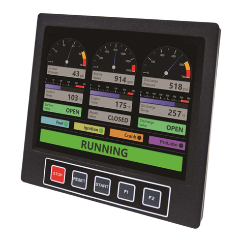
CPU-XL VariSpark Digital Ignition System with Enhanced Display
Form CPU-XL VariSpark IOM 07-21

CPU-XL VariSpark IOM 07-21
All rights reserved © ALTRONIC, LLC 2021 2
1.0 OVERVIEW
1.1 The Altronic CPU-XL VariSpark Digital Ignition with enhanced display is a DC-
powered, microprocessor-based, capacitor discharge system applicable to slow
and medium speed, stationary, natural gas-fueled engines. It features crankshaft-
triggered timing accuracy and the capability to vary timing electronically by
several means, including an external 4-20mA control signal. This system is field-
programmable and oers a variety of advanced control, emissions reduction,
primary and spark diagnostic, self-diagnostic, serial communications and engine
protection features.
2.0 COMPONENTS
2.1 The system consists of a Logic/Display Module, a Junction/Diagnostic Module,
up to two Output Modules, up to four EZRails, two magnetic pickups and cables,
a Hall-eect pickup and trigger magnet (4-cycle engines only), appropriate
cables and harnesses, and an ignition coil for each spark plug. For a total system
overview, refer to Figure 1.
2.2 Logic/Display Module (291400-1) – Typically mounted in the engine control
panel, the Logic/Display Module has a graphical, color, backlight LCD display
showing the operating status, engine RPM, energy level, spark profile in use,
current loop input value and ignition timing. Additional display screens show
set-up and diagnostic information. Its menu structure is similar to those of the
CPU-2000 and CPU-95 systems.
2.3 Output Module(s) (291410-1)– Connected by harness to the Junction/Diagnostic
Module, an Output Module is installed on each bank of the engine. This device
generates the high voltage DC power and distributes this energy to the ignition
coil rails. Two modules are required to run V-type engines with one module
generating firings for each bank. Each Output Module can drive 10 separate
outputs and each output can be used to drive one coil or two coils for engines
having two spark plugs per cylinder.
2.4 Junction/Diagnostic Module (291405-2) – The Junction/Diagnostic Module
replaces the traditional on-engine junction box and serves several purposes. The
Junction/Diagnostic Module wiring is used to determine which cylinder is fired for
each output event of the Logic/Display Module. The CPU-XL ignition fires in the
same order as all other Altronic digital ignition systems. The first firing event is the
one following the reset. The firing events are brought out in order of occurrence
(1, 2, 3, 4…) on the 20-position terminal strip inside the Junction/Diagnostic
Module.
2.5 Ignition Coil/EZRail Module(s) – The CPU-XL VariSpark ignition coils and primary
wiring are integrated into a series of engine-specific EZRail modules. These
coil/rail modules are connected by harness to the Output Module and deliver a
factory-certified and tested mounting and on-engine wiring solution. Primary
cables and associated connectors are eliminated in the high current portion of the
system, thereby enhancing reliability.
2.6 Harnesses (all connectors sealed with epoxy potting)
Logic/Display Module to Junction/Diagnostic Module – 293030-L, one straight
17-pin connector.
Junction/Diagnostic Module to Output Module – 793101-L, one straight and one
right-angle 19-pin connector or 793102-L, two right-angle 19-pin connectors.
Output Module to EZRail Assembly – 793102-L, two right-angle 19-pin connectors (max. 48").
2.7 To allow for a simple and economical upgrade of existing Altronic CPU-2000
installations, the CPU-XL utilizes existing CPU-2000 magnetic pickups, Hall-eect
pickup and trigger magnet, pickup cables, and inter-module wiring harnesses.
2.8 Power requirement is 24Vdc, 30 amperes.
NOTE: All new installations must use
the 291405-2 Junction/Diagnostic
Module and the 791401-2 Coil.
The -1 versions of these parts are for
replacement application only.
WARNING: Deviation from these
instructions may lead to improper
engine operation which could cause
personal injury to operators or other
nearby personnel.
The ignition system must be
configured prior to use on an
engine. Refer to section 19.9 To
view the current configuration.
Reference form CPU-XL VariSpark
PI for instructions describing how
to configure the ignition system.
Verify eeprom programming prior to
starting engine.

CPU-XL VariSpark IOM 07-21
All rights reserved © ALTRONIC, LLC 2021 3
3.0 MOUNTING THE LOGIC/DISPLAY MODULE
3.1 The CPU-XL Logic/Display Module is preferably panel-mounted o the engine in such
a manner as to minimize exposure to vibration. Refer to Figure 2 for dimensions.
3.2 The Logic/Display Module should be mounted within 50 feet (15m) of the
Junction/Diagnostic Module.
3.3 Operating temperature range is -40°F to 158°F (-40°C to 70°C). Humidity
specification is 0-95%, non-condensing. Housed in a NEMA 4 enclosure, the
CPU-XL Logic/Display Module is splash resistant; however, the mounting site
should provide as much protection from inclement weather as is practical. Avoid
mounting the LCD display and keypad in direct sunlight.
4.0 MOUNTING THE OUTPUT MODULES
4.1 Refer to Figure 3 for physical dimension details. Select a mounting location meeting
the following requirements:
n On the engine, within 50 ft. (15m) of the Logic/Display Module.
n Within 15 ft. (4.5m) of the Junction/Diagnostic Module.
n Within 6 ft. (1.8m) of the ignition rails.
n The maximum ambient temperature must not exceed °F (°C).
4.2 The Output Module enclosure should be fastened securely to a rigid engine
bracket using the shock mounts provided.
5.0 MOUNTING THE JUNCTION/DIAGNOSTIC
MODULE
5.1 Refer to Figure 4 for physical dimension details. Select a mounting location
meeting the following requirements:
n Within 20 ft. (6m) of the Output Modules.
n The front panel door of the Junction/Diagnostic Module should be easily
accessible and free to swing open.
n The maximum ambient temperature must not exceed °F (°C).
5.2 The Junction/Diagnostic Module enclosure should be fastened securely to a rigid
engine bracket using the shock mounts provided.
6.0 MOUNTING FLYWHEEL GEAR/DRILLING FLYWHEEL
HOLES
6.1 The Altronic CPU-XL system requires a source of angular position pulses from the
engine crankshaft. This can be a flywheel ring gear, a separately provided gear or
specially drilled holes in the flywheel. The source of position pulses must meet the
following requirements:
n Must be ferrous material, diameter of 18" or greater.
n No. of teeth or holes must be 180 or greater.
n Maximum run-out referenced to the pickup of .007". Refer to Figures 5
and 6 for further details.
7.0 MOUNTING THE MAGNETIC PICKUPS
7.1 The system requires two magnetic pickup signals: the angular position pulses from
the gear or drilled holes and a reset pulse near the most advanced firing position
desired for no. 1 cylinder. The pickups must be mounted to rigid brackets to
maintain an air gap of .015" ± .005" with respect to the rotating gear or flywheel. It
is also important for maximum signal eciency that the centerline of the rotating
part pass through the center of the pickup. See Figure 5.

CPU-XL VariSpark IOM 07-21
All rights reserved © ALTRONIC, LLC 2021 4
8.0 MOUNTING THE FLYWHEEL RESET PIN
8.1 Set the engine with no. 1 cylinder six (6) degrees ahead of the most advanced
firing point. Mark a point on the flywheel directly opposite the pole piece of the
reset magnetic pickup; then rotate the engine to a position convenient for drilling
and tapping the flywheel at the point marked above. The reset pin should be
made from a steel (magnetic) 1/4"-20 bolt or stud. See Figure 5.
8.2 Rotate the engine to the original set point and adjust the air gap between the end
of the reset pin and the magnetic pickup at .010" using a feeler gauge.
9.0 MOUNTING THE CYCLE TRIGGER (4-cycle engine only)
9.1 The trigger magnet (260604, 260605 or 720002) must be mounted on the engine
camshaft or other accessory drive operating at camshaft speed. An M8 (8mm)
tapped hole, 0.5 inches (13mm) deep is required. See Figures 7, 8 or 9 for details.
The magnet MUST rotate on a diameter NOT EXCEEDING:
n 6 inches (152mm) for magnet 720002, or
n 15 inches (381mm) for magnet 260604 or 260605.
n Maximum run-out referenced to the pickup of .007”
9.2 Set the engine on the COMPRESSION stroke of no. 1 cylinder with the reset pin
DIRECTLY OPPOSITE the reset pickup. The Hall-eect pickup (591014-x) must
be mounted DIRECTLY OPPOSITE the trigger magnet coincident with the reset
pickup and pin being lined-up.
10.0
LOGIC/DISPLAY MODULE ELECTRICAL HOOK-UP
10.1
The power connections to the CPU-XL must be in accordance with the National
Electrical Code or other applicable country code. The CPU-XL is suitable for
installation in Class I, Division 2, Group D locations.
10.2
The Logic/Display Module must have its own 24Vdc power connection. Although
the device has internal protective fuses (3 amp), an external fuse near the power
source is recommended.
10.3
Power wiring and signal wiring must be in separate conduits and conduit entries into the
Logic/Display Module to avoid undesired electrical interaction. All conduit entries are
sized for a 1/2"-14 NPT male conduit fittin g. Separate as follows (refer to Figure 11):
n RIGHT CONDUIT ENTRY Power wiring and cable −xx to
Diagnostic Module
n CENTER CONDUIT ENTRY Magnetic pickups and Hall-eect pickup
n LEFT CONDUIT ENTRY Control inputs, serial communications, and
alarm outputs
10.4
RIGHT ENTRY: Input power supply wires (16 AWG minimum) should enter the
right conduit entry and connect to the 24Vdc supply terminals of the terminal
block. The interface cable 293030-xx, connecting the Logic/Display Module with
the Junction/Diagnostic Module, also enters through the right conduit entry. Refer
to Figures 11 and 12 for connection details.
10.5
CENTER ENTRY: Run a separate conduit for the two (2) magnetic pickup cable
assemblies. These should enter through the center entry in the Logic/Display
Module box and terminate as shown in Figure 11.
4-CYCLE ENGINE ONLY: The cable from the Hall-eect pickup also enters
through the center entry and connects as shown.
10.6
LEFT ENTRY: A separate conduit must be used to the left-hand entry for all
connections to the user interface terminal strips in the Logic/Display Module. Use
24 AWG, UL style 1015 wire or shielded cable for these connections; the 24 AWG
wire is available from Altronic under part no. 603102 (black) or 603103 (white).
A. SHUTDOWN INPUT (terminal 4): Use to stop the ignition for engine shutdown.
This input is open for normal operation of the system and is connected to
engine ground to inhibit ignition firings. NOTE: This is a 5-volt low level signal.
NOTE: The Hall-eect signal and
the reset pickup signal must occur
at the same time for the system to
function.
The Hall-eect pickup dimensions
are shown in Figure 10. The air gap
between the Hall-eect pickup and
trigger magnet must not exceed
.040" (1.0mm).

CPU-XL VariSpark IOM 07-21
All rights reserved © ALTRONIC, LLC 2021 5
B. ALARM OUT (terminal 5), SHUTDOWN OUT (terminal 6), FIRE CONFIRM OUT
(terminal 7): Three output switches are available for monitoring ignition system
status. Each output consists of a solid state switch normally closed to a single
common rail COMMON OUT (terminal 8). The switches are rated
75mA @ 100Vdc. These output switches are electrically isolated from all other
terminals. The recommended hook-up is shown in Figure 11.
C. 4-20mA TIMING CONTROL INPUT: The 4-20mA timing control loop connects
to terminals 9(+) and 10(–). This input is electrically isolated from all other
terminals; refer to Figures 11 and 15.
D. MISC INPUT (terminal 11): Provides for control of various user-selected
features. This input is normally open; connect to engine ground to activate the
selected feature (see Figure 11). NOTE: This is a 5-volt low-level signal.
E: 4-20mA SPARK NUMBER CONTROL INPUT: The 4-20mA spark number
control loop connects to terminals 3(-) and 4(+) of the 2nd (rear) terminal strip.
This input is electrically isolated from all other terminals.
F: SPARK NUMBER OVERRIDE (rear terminal 1): Provides a user-configurable
override of the current selected spark profile number. This input is normally
open; connect to engine ground to activate the selected feature. NOTE: This is
a 5-volt low-level signal.
G: RS-485: The terminals: 5(GND), 6(–), and 7(+) provide an RS-485 port for
external control VIA PC or PLC.

CPU-XL VariSpark IOM 07-21
All rights reserved © ALTRONIC, LLC 2021 6
11.0
OUTPUT MODULE ELECTRICAL HOOK-UP
11.1
All required connections to the CPU-XL Output Module are made through
harnesses using multi-pin, threaded connectors.
11.2
BOTTOM 19-PIN CONNECTOR: The bottom 19-pin of the Output Module
connects to the Junction/Diag Module by means of harness series 793101-L or
793102-L. Insert the connector into the bottom Output Module receptacle and
hand-tighten; then carefully tighten an additional one-sixth turn with a wrench.
11.3
SIDE 19-PIN CONNECTORS: The 19-pin connectors “A on left” and “B on right”
are output connections to the EZRails by means of harness series 793102-L.
11.4
7-PIN CONNECTOR: The 7-pin connector is reserved for future development and is
not presently utilized. A sealed connector cap should be in place over this connector.
12.0
JUNCTION/DIAGNOSTIC MODULE ELECTRICAL
HOOK-UP
12.1
All required external connections to the CPU-XL Junction/Diagnostic Module are made
via harnesses using multi-pin, threaded connectors.
12.2
17-PIN CONNECTOR: Connection to the 17-Pin receptacle of the Junction/
Diagnostic Module is made using harness 293030-L, which has been properly
terminated inside the Logic/Display Module as described in section 10.0
12.3
19-PIN CONNECTORS: The 19-Pin connectors of the Junction/Diagnostic Module
mate to harnesses 793101-L or 793102-L coming from the Output Modules. Take
care that the harnesses route the proper signals to the appropriate bank (Output
Module) according to the application diagram developed for the installation on your
engine. Insert the connector into the receptacle and hand-tighten, then carefully
tighten an additional one-sixth turn with a wrench.
12.4
The firing order of the engine, as well as the cylinder identification (1, 2, 3…or 1L,
1R, 2L…or other), should be recorded on the chart in Figure 1.
12.5
After the correct firing order is identified by cylinder, and the cylinders have
been labeled, the specific ignition rail, which will be used to fire the coils for each
cylinder, can be identified. Each rail connects to one connector of an Output
Module using the harness provided.
12.6
The Junction/Diagnostic Module wiring is is used to determine which cylinder
is fired for each output event of the Logic/Display Module. The CPU-XL ignition
always fires in the same order as all other Altronic digital systems. The first firing
event is the one following the reset. The firing events are brought out in order of
occurrence (1, 2, 3, 4…) on the 20-position terminal strip inside the Junction/
Diagnostic Module. With the Junction/Diagnostic Module mounted with the
20-position terminal strip horizontal, and above the two vertical 10-position
output strips and connectors, the firing events are in order from left to right, going
from the first to the twentieth firing.
12.7
Wiring the Junction/Diagnostic Module internal jumpers to match the specific firing
order of the engine. As with a traditional ignition system such as the CPU-2000, the
igniton outputs must be matched to the proper cylinders according to the firing order
of the engine. This is done inside the Junction/Diagnostic Module using logic level
20AWG, 503128 jumper wires connected between the pluggable terminal blocks.
12.8
Inside the Junction/Diagnostic Module, two vertical, 10-position, terminal strips
are used to connect to the Output Modules via the 79310x-L cables. Each
10-position vertical strip is used to connect to one Output Module, which, in turn,
connects to the two ignition rails on a single bank of the engine. The upper five
terminals go to one rail through one connector of the Output Module and the lower
five terminals go to the other rail mounted on the same bank and connected to the
other connector of the same Output Module. This is more easily understood if the
entire ignition system is viewed as four separate systems, each of which can fire 1
to 5 cylinders with single or dual coils. Each Output Module contains two separate,
five-cylinder ignitions, and each one of these connects to a single rail. Single spark
plug per cylinder engine applications use engine rails having a maximum of five
coils per rail. Dual spark plug applications can have a maximum of ten coils per rail.
All applications service a maximum of five cylinders per rail.

CPU-XL VariSpark IOM 07-21
All rights reserved © ALTRONIC, LLC 2021 7
Point-to-point connections of the system.
Junction Terminal ID
on Label inside
Junction/Diagnostic
Module
Cable to
Output
Module
Output Module
Harness to EZRail
Connector Pin
Cyl. Position, counting
from end away from 19-pin
connector
Rail
Designator
Rail 1 Terminal 1 Out 1 Pin A Connector a Pin A 1 Far end of engine
Rail 1 Terminal 2 Out 1 Pin B Connector a Pin B 2
Rail 1 Terminal 3 Out 1 Pin C Connector a Pin C 3
Rail 1 Terminal 4 Out 1 Pin D Connector a Pin D 4
Rail 1 Terminal 5 Out 1 Pin E Connector a Pin E 5
Junction
Terminal ID
on Label
Cable to
Output
Module Wire
Output Module
Harness to EZRail
Connector Pin
Rail Position, counting
from end away from 19-pin
connector
Rail
Designator
Rail 2 Terminal 6 Out 1 Pin F Connector b Pin E 5
Rail 2 Terminal 7 Out 1 Pin G Connector b Pin D 4
Rail 2 Terminal 8 Out 1 Pin H Connector b Pin C 3
Rail 2 Terminal 9 Out 1 Pin J Connector b Pin B 2
Rail 2 Terminal 10 Out 1 Pin K Connector b Pin A 1 Far end of engine
Junction
Terminal ID
on Label
Cable to
Output
Module Wire
Output Module
Harness to EZRail
Connector Pin
Rail Position, counting
from end away from 19-pin
connector
Rail
Designator
Rail 4 Terminal 1 Out 2 Pin K Connector b Pin A 1 Far end of engine
Rail 4 Terminal 2 Out 2 Pin J Connector b Pin B 2
Rail 4 Terminal 3 Out 2 Pin H Connector b Pin C 3
Rail 4 Terminal 4 Out 2 Pin G Connector b Pin D 4
Rail 4 Terminal 5 Out 2 Pin F Connector b Pin E 5
Junction
Terminal ID
on Label
Cable to
Output
Module Wire
Output Module
Harness to EZRail
Connector Pin
Rail Position, counting
from end away from 19-pin
connector
Rail
Designator
Rail 3 Terminal 6 Out 2 Pin E Connector a Pin E 5
Rail 3 Terminal 7 Out 2 Pin D Connector a Pin D 4
Rail 3 Terminal 8 Out 2 Pin C Connector a Pin C 3
Rail 3 Terminal 9 Out 2 Pin B Connector a Pin B 2
Rail 3 Terminal 10 Out 2 Pin A Connector a Pin A 1 Far end of engine
(1)
(2) (3)
(4)

CPU-XL VariSpark IOM 07-21
All rights reserved © ALTRONIC, LLC 2021 8
13.0
DC POWER HOOKUP: 293030-XX CABLE
13.1
The power connections to the CPU-XL must be in accordance with the National
Electrical Code or other applicable country code. The CPU-XL is suitable for
installation in Class I, Division 2, Group D locations.
13.2
It is necessary to split the control cable and power leads of the 293030 cable in an
engine-mounted Junction/Diagnostic Module or conduit tee. This box should be
separate from the main Junction/Diagnostic Module used to terminate the output
harness(es) to the ignition coils. Refer to Figure 12.
13.3
The CPU-XL system can be powered in one of the following ways:
A. 24 volt battery with charger.
B. DC power supply capable of furnishing 24-28Vdc at currents up to 30
amperes.
IMPORTANT: For proper operation of the CPU-XL system, voltage and current
supplied must be sucient during all selected modes of operation. Figure 14
provides these details regarding the DC power hook-up:
1. CURRENT DRAW PER SYSTEM – formula varies depending on number of
outputs used, engine cycle and RPM, and spark number used.
2. MINIMUM WIRE GAUGE REQUIREMENTS – Chart 1 of Figure 16
gives the requirement vs. the length of run between the power source and
the CPU-XL Junction/Diagnostic Module.
3. MULTIPLE ENGINE INSTALLATIONS – It is recommended that each
engine be supplied by a dedicated power supply capable of up to 30
amperes of 24 volt DC power. If a large, uninterruptible, bussed supply is
available it can be used for multiple engines, but each igniton should be
wired back to the supply main independently of the other ignitions.
14.0
PRIMARY WIRING
14.1
There is no traditional primary wiring required for the use of the CPU-XL ignition
system. All of the necessary primary wiring is supplied pre-configured inside the
flexible conduit harnesses and the ignition rails.
15.0
SECONDARY WIRING
15.1
Mount the ignition rails as close as possible to the engine spark plugs consistent with
a secure mounting and avoidance of temperatures in excess of 185°F (85°C).
15.2
The spark plug leads should be fabricated from silicone insulated 7mm cable with
suitable terminals and silicone spark plug boots. The use of leads with resistor spark
plug boots (Altronic series 59320x-xx) is recommended to minimize interference from
emitted RFI on the operation of other nearby electronic equipment. Another option
is the use of suppression ignition cables. It is also essential to keep spark plug leads
as short as possible and in all cases not longer than 24 inches (600mm). Spark plug
leads should be kept at least 2 inches (50mm) away from any grounded engine part.
In deep spark plug wells, use rigid insulated extenders projecting out of the well.
15.3
The use of a clear, silicone grease (such as Dow Corning DC-4, G.E. G-623 or GC
Electronics ZS) is recommended for all high-tension connections and boots. This
material helps seal out moisture and prevent corrosion from atmospheric sources.
NOTE: The negative (-) of the 24Vdc
supply MUST BE COMMON WITH
ENGINE GROUND. Engines using
positive ground DC accessories
or starter motors will require a
separate dedicated power supply.
WARNING: Although the device has
internal protective fuses (3 AMP
in the Logic/Display Module, and
15 AMP in the Junction/Diagnostic
Module), two external 20 amp
fuses near the power source are
recommended for the protection
of engine and building wiring. This
will reduce the possibility of a fire
occurring in the event of a short
circuit in the wiring. See Figure 16.

CPU-XL VariSpark IOM 07-21
All rights reserved © ALTRONIC, LLC 2021 9
16.0
INPUT/OUTPUT WIRING
16.1
To shut-o the DC-powered CPU-XL system, a special input (SHUTDOWN INPUT
terminal 4) in the Logic/Display Module is provided. This input is open for normal
operation and is connected to engine ground to initiate an ignition shutdown. Use a
switch rated 24Vdc, 0.5 amps. Refer to section 10.6 A, and Figure 11 for details.
16.2
The Logic/Display Module includes two isolated current loop inputs. The first can
be configured to control spark timing. Reference the programming instructions,
form CPU-XL VariSpark PI. See Figure 11 for Terminal Block ID.
16.3
The second current loop input can be configured to control the spark number.
Reference the programming instructions, form CPU-XL VariSpark PI. See Figure
11 for Terminal Block ID.
16.4
Two digital inputs are provided inside the ignition system. These logic-level inputs
are active when shorted to ground. The first, MISC. INPUT, controls one-step
retard, and the second, SPK OVERRIDE, controls the spark override number. See
Figure 11 for Terminal Block ID.
17.0
COMMUNICATIONS
17.1
The Logic/Display Module incorporates a half-duplex RS-485 port which is
Modbus RTU slave compliant. The protocol used follows the Modicon Modbus
RTU standard. A PC (personal computer) or a PLC (programmable logic controller)
can be connected to the RS-485 port to perform remote monitoring or control
functions. This port is also used to configure the ignition system for its application
using a PC and the CPU-XL VariSpark PC terminal software. For a complete list of
the Modbus register addresses, see section 32.0. The CPU-XL VariSpark terminal
program CD contains a PC-based Modbus compatible monitoring program which
can be used to access the ignition data remotely.
17. 2
Logic/Display Module: serves as the user interface for the CPU-XL VariSpark
ignition system. A proprietary CANBUS communications format is used to
connect the Logic/Display Module to the Junction/Diagnostic Module.
17. 3
An internal USB port can also be configured as another Modbus RTU interface.
18.0
DISPLAYS AND INDICATORS
18.1
A graphical, color-changing, back-lit, LCD display provides output to the user. A
sealed-membrane keypad accepts user input. The LCD display and the keypad
function together to provide an interactive user interface that prompts the user as
dierent functions are selected. The screen background color indicates status:
green indicates normal condition, yellow indicates a warning and remains until
a key is pressed, and red indicates a fault and remains until a key is pressed.
Pressing any key results in a white background which remains for 30 seconds.
18.2
All actions and adjustments are immediate and are performed on an incremental
basis using up and down arrow keys. All keypad adjustments, except individual
oset timing adjustments, are performed directly in non-volatile EEPROM
memory. This EEPROM memory retains previous settings even after an engine
shutdown, or an ignition power down.
18.3
Green LED indicators are provided inside the ignition unit for troubleshooting:
POWER LED: on to indicate that the unit has power and the microprocessor is
running. The Power LED is o to indicate that the unit has no power.
TX LED: flashes to indicate that the ignition unit is transmitting on the RS-485
serial link.
RX LED: flashes to indicate that the ignition unit is receiving on the RS-485
serial link.
ALARM LED: turns on to indicate that a warning or fault is present. The ALARM LED
flashes when an acknowledged warning is present.

CPU-XL VariSpark IOM 07-21
All rights reserved © ALTRONIC, LLC 2021 10
19.0
UNDERSTANDING THE HOME SCREEN
19.1
A series of home screens are used to describe the current status of the ignition
system. The LCD display always reverts back to one of the home screens after
a keypad operation is completed or times out. The home screen is designed to
display the most critical operating parameters on one screen.
19.2
The READY message is displayed when the ignition is ready for the engine to
crank for starting.
19.3
Once the engine begins turning, the SYNCING message is displayed while the
ignition system verifies signals from the engine pickups.
After the ignition system has synchronized with the engine, the system displays
TRYING. This message means that the system has begun firing.
19.4
The FIRING message is displayed after one channel of each Output Module has
fired at least once. When this is displayed, the fire-confirm signal is also closed.
Additional data is provided on this screen to describe the selected mode of
operation for the ignition. The spark mode (#1-8) is described beneath the status.
19.5
The STALLED message is displayed when a loss of rotation is detected after the
ignition is firing and neither a SHUTDOWN or FAULT has occurred. This signifies
that the engine has stopped without any detected cause from the ignition system.

CPU-XL VariSpark IOM 07-21
All rights reserved © ALTRONIC, LLC 2021 11
19.6
The WARNING message will supersede all of the above home screens if a
diagnostic warning condition is present. When a diagnostic warning exists, a
** Press DIAG ** message will appear on the display. The Ignition Module will
continue to operate under a warning condition while alerting the operator of a
potential problem in several ways: by turning on the Alarm LED in the Ignition
and by changing the state of the Alarm Out switch (switch opens), and changing
the screen background color to yellow. The Logic/Display Module will display the
WARNING message. The various types of diagnostic warnings are described in
section 25.6.
19.7
The FAULT message will supersede all of the above home screens if a diagnostic
fault condition is present. When a diagnostic fault exists, a ** Press DIAG **
message will appear on the display. The ignition system will stop operating under
a fault condition and will alert the operator to the problem in several ways: by
changing the state of the Fire Confirm Out switch (switch opens), by turning on
the alarm LED on the Logic/Display Module, by changing the state of the Alarm
Out switch (switch opens), and by displaying the Fault message and changing
the screen background color to red. The various types of diagnostic faults are
described in section 25.5.

CPU-XL VariSpark IOM 07-21
All rights reserved © ALTRONIC, LLC 2021 12
19.8
The SHUTDOWN screen will supersede all other home displays if the logic level
shutdown input of the Ignition Module. This screen indicates that the ignition
is not firing because a shutdown input was triggered to shutdown the engine. If
a diagnostic fault or warning exists while the ignition is in shutdown, a ** Press
DIAG ** message will appear on the display. The Fire Confirm Out switch will
change state (switch opens) and the other outputs will function as described
above based on the existence of faults or warnings.
19.9
From the HOME SCREEN, pressing the NEXT key allows you to cycle through the
configuration comments which describe the configuration of the ignition system.
AT
PRESS TO
GO TO
NEXT
NEXT
The configuration screens are shown starting on the next page.

CPU-XL VariSpark IOM 07-21
All rights reserved © ALTRONIC, LLC 2021 13
The following types of screens can be viewed by pressing NEXT to advance.
FIRING PATTERN CODE: (JB.HC)
SPECIAL FEATURE CODE: (#)
( STEP DEFAULT)
IGNITION MODULE TYPE: ( P A R T
NUMBER)
NEXT
LOCATION:
USER SPECIFIED DESCRIPTION
NEXT
DATE CONFIGURED: (−−)
TIME CONFIGURED: (:)
CONFIGURED BY: (HD)
TERMINAL VERSION #: (v.)
NEXT
CURRENT LOOP CURVE DESCRIPTION
AT mA ° RETARD
AT mA ° RETARD
USER SPECIFIED DESCRIPTION
NEXT
RPM RETARD CURVE DESCRIPTION
YES⁄NO Status
RPM RANGE Retard Range
⁄ ⁄ ret
NEXT

CPU-XL VariSpark IOM 07-21
All rights reserved © ALTRONIC, LLC 2021 14
ENGINE NUMBER OR DESCRIPTION
USER SPECIFIED DESCRIPTION
NEXT
SPECIAL USER COMMENTS AREA #
USER SPECIFIED COMMENTS
NEXT
SPECIAL USER COMMENTS AREA #
USER SPECIFIED COMMENTS
NEXT
PRESS NEXT TO RETURN TO HOME
SCREEN
NEXT
PRESS ESC. FROM ANY SCREEN TO
RETURN TO HOME SCREEN
ESC
NOTE: Because EEPROMS can
be reconfigured (using a PC and
Altronic’s configuration software),
these comments should be viewed to
identify and verify the configuration
settings of the ignition prior to
operation. Refer to the programming
instructions, form CPU-XL VariSpark
PI, for further information on
configuration.

CPU-XL VariSpark IOM 07-21
All rights reserved © ALTRONIC, LLC 2021 15
BREAKDOWN OF FIRING PATTERN CODE: JB.LC#
JREPRESENTS THE NUMBER OF OUTPUTS USED, IN THIS CASE
(F =, L = , ETC.)
REPRESENTS THE CYCLE TYPE OF THE ENGINE
= TWO−CYCLE
= FOUR−CYCLE
BREPRESENTS THE ALTRONIC PATTERN CODE (SEE FORM CPU−XL VA−
RISPARK AL)
REPRESENTS THE NUMBER OF GEAR TEETH OR HOLES TO BE SENSED
LREPRESENTS A DESIGNATOR FOR CPU−XL VARISPARK VERSION
CREPRESENTS THE CURRENT LOOP RETARD CURVE TYPE
A = ° AT MA ⁄ ° AT MA
B = ° AT MA ⁄ ° AT MA
C = ° AT MA ⁄ ° AT MA
D = ° AT MA ⁄ ° AT MA
E = ° AT MA ⁄ ° AT MA
N = SPECIAL NON−STANDARD TIMING CURVE VS. CURRENT OR RPM,
NON−FACTORY PROGRAMMED
S =SPECIAL NON−STANDARD TIMING CURVE VS. CURRENT OR RPM,
FACTORY
PROGRAMMED
X =NO CURRENT LOOP CURVE
# REPRESENTS THE SPECIAL FEATURE CODE
(TOTAL SUM OF ALL SELECTED OPTIONS; =DEFAULT)
= USE STEP RETARD WHEN RPM IS LESS THAN
= USE STEP RETARD WHEN MISC INPUT IS GROUNDED

CPU-XL VariSpark IOM 07-21
All rights reserved © ALTRONIC, LLC 2021 16
20.0
ADJUSTING GLOBAL RETARD
20.1
Global retard is an adjustment aecting the timing of all cylinders equally. This
adjustment can be equated to the manual timing switch of the Altronic CPU-XL
VariSpark system. Adjustments made as described below will be in eect until
another adjustment is made.
20.2
To adjust global retard:
FROM PRESS
TIMING
THEN AT PRESS
THEN AT PRESS
THEN AT NOTE: RESULTANT
TIMING SHOWN ON
BOTTOM LINE.
PRESS TO PRESS TO PRESS TO
INCREASE DECREASE EXIT
RETARD RETARD
ESC
⬆
⬇
⬆⬇

CPU-XL VariSpark IOM 07-21
All rights reserved © ALTRONIC, LLC 2021 17
20.3
The increment of timing change is dependent on the number of holes or teeth
being sensed. The minimum timing change is defined as follows.
The timing increment is “⁄N” degrees, where N = no. of holes or teeth.
Example: ⁄ = .° min. timing increment.
20.4
Global spark timing is determined based on the sum of several spark retard
components which include manual retard, current loop retard, RPM retard, and
1 step retard. The range of total retard is limited to 255 X timing increment. When
the sum of all retard components reaches 255 X timing increment, the actual
timing will be at the retard limit.
21.0
SELECTION OF GLOBAL TIMING MODES
21.1
Several options exist with regard to global timing modes. Once the global timing
mode menu is entered as described below, the status of each option can be
viewed and changed.
FROM PRESS
TIMING
THEN AT PRESS
THEN AT PRESS
⬆
⬇

CPU-XL VariSpark IOM 07-21
All rights reserved © ALTRONIC, LLC 2021 18
21.2
The first mode selection can enable or disable the pre-configured retard curve
controlled by the 4-20mA current loop input. The choices are ON or OFF, with
the active selection displayed in capital letters. A PC is required to configure the
4-20mA curve; reference the programming instructions, form CPU-XL VariSpark
PI. When the current loop is on, the current loop value is displayed (xx.x mA) with
the “A” capitalized. When the current loop is o, the value is displayed (xx.x ma)
with the lower case “a”.
AT NOTE: DISPLAY
SHOWS CURRENT
LOOP ON.
TO TO FOR TO
TURN TURN NEXT EXIT
ON OFF OPTION
NEXT
ESC
21.3
The next mode selection can enable or disable the pre-configured retard curve
controlled internally by engine RPM. To configure the RPM retard curve, refer to
the Programming Instructions, Form CPU-XL VariSpark PI.
AT THE NOTE: DISPLAY
NEXT SHOWS RPM
OPTION MAP OFF.
SCREEN
TO TO FOR TO
TURN TURN NEXT EXIT
ON OFF OPTION
NEXT
ESC
⬆⬇
⬆⬇

CPU-XL VariSpark IOM 07-21
All rights reserved © ALTRONIC, LLC 2021 19
21.4
The next mode selection can increase or decrease the 1 step retard value. The
first screen below is displayed when 1 step retard is both configured and is active.
The second screen below is displayed when the 1 step retard is configured but
not active. The default configuration selects 1 step retard to be controlled by the
Misc. Input terminal. The additional retard would be implemented when the input
is grounded. The third screen below is displayed when the 1 step retard feature is
not configured. The actual engine timing is displayed on this screen so the eect
of 1 step retard can be seen during adjustments (if the Misc Input terminal is
grounded).
AT THE
NEXT
OPTION
SCREEN
OR
OR NOTE: 1 STEP
RETARD NOT
CONFIGURED.
TO TO TO GO TO
INCREASE DECREASE BACK TO E X IT
FIRST
⬆⬇NEXT ESC

CPU-XL VariSpark IOM 07-21
All rights reserved © ALTRONIC, LLC 2021 20
22.0
ADJUSTING INDIVIDUAL OFFSETS
22.1
The timing of individual cylinders can be oset by up to 3 degrees of advance or
retard from the global timing of the engine. The values are not saved in EEPROM
memory. See section 23.2.
22.2
Enter the individual timing adjustment menu as described below.
FROM PRESS
TIMING
THEN AT PRESS
THEN AT PRESS
22.3
The individual timing adjustment screen identifies the primary output to be
adjusted, and the degrees of oset in use for the output.
THEN AT NOTE: 0.0 degrees
advance for
output A.
TO ADJUST TO SELECT TO SELECT
INDIVIDUAL CYL NEXT PREVIOUS
TIMING CYLINDER CYLINDER
OFFSET
NEXT
SETUP
TO VIEW TO GO TO TO GO TO TO
CURRENT CYLINDER DIAGNOSTIC RETURN
CYLINDER SELECT OFFSET TO HOME
GRAPH
F1
F4
SCREEN
ESC
IADVANCE TO THE TO RESET THE
NEXT CYLINDER CYLINDER TIMING
IN THE FIRING ORDER TO EEPROM
TIMING
STORED VALUE
RESET
⬇
⬆
NOTE: In applications with narrow
firing angles, the adjustment range
may be limited.
NOTE: Cylinder identification infor-
mation describes:
1L = Cylinder Label
01 = Firing Order
1A = Rail/Coil Position.
⬆⬇
F3
Table of contents
Other Altronic Control System manuals
