manuals.online logo
Brands
  1. Home
  2. •
  3. Brands
  4. •
  5. Altronix
  6. •
  7. Power Supply
  8. •
  9. Altronix SMP3CTX Series Operating and maintenance instructions

Altronix SMP3CTX Series Operating and maintenance instructions

SMP3CTXseries -1-
Power Supply Voltage Output Specifications: *
Output VDC Switch Position Max. Load DC
12VDC SW1 - Closed (Fig. 1b, pg. 3) 2.5 amp
24VDC SW1 - Open (Fig. 1b, pg. 3) 2.5 amp
*Specified at 25˚ C ambient.
Installation Instructions:
Wiring methods shall be in accordance with the National Electrical Code/NFPA 70/NFPA 72/ANSI, and with all local
codes and authorities having jurisdiction. Product is intended for indoor use only.
1. Mount unit in desired location. Mark and predrill holes in the wall to line up with the top two keyholes in the
enclosure. Install two upper fasteners and screws in the wall with the screw heads protruding. Place the enclosure’s
upper keyholes over the two upper screws, level and secure. Mark the position of the lower two holes. Remove the
enclosure. Drill the lower holes and install the three fasteners. Place the enclosure’
supper keyholes over the two
upper screws. Install the two lower screws and make sure to tighten all screws (Enclosure Dimensions, pg. 4).
Secure enclosure to earth ground.
2. Set SW1 on the power supplyboard to the desired DC output voltage
(Power SupplyV
oltage Output Specification Chart).
SMP3CTX Series Power Supply Configuration Reference Chart:
Overview:
These units will convert a 115VAC or 230VAC, 50/60Hz input, into a regulated 12VDC or 24VDC output up 2.5 amp of
continuous load current (see specifications).
Specifications:
• Universal 115/230VAC input.
• Maximum charge current .5 amp.
• Filtered and electronicallyregulated outputs.
• Built-in charger for sealed lead acid or gel type batteries.
• Automatic switch over to stand-by battery when
AC fails (zero voltage drop).
• AC input and DC output LED indicators.
• Short circuit and thermal overload protection.
• Complete with power supply, power distribution module
(when applicable), enclosure, cam lock & batteryleads.
• Power on-off switch.
Supervised models only:
• AC fail supervision (form "C" contacts).
• Low battery supervision (form "C" contacts).
SMP3CTX Series - Installation Guide
SMP3CTX - 1 - - - - .65 / .35 2.5
SMP3PMCTX - 1 - - - x .65 / .35 2.5
SMP3PMCTXX - 1 - - - x .65 / .35 2.5
SMP3PMP4 PD4 4 x - 3.5 x .65 / .35 2.5
SMP3PMP4CB PD4CB 4 - x 2.5 x .65 / .35 2.5
SMP3PMP8 PD8 8 x - 3.5 x .65 / .35 2.5
SMP3PMP8CB PD8CB 8 - x 2.5 x .65 / .35 2.5
SMP3PMP16 PD16W 16 x - 3.5 x .65 / .35 2.5
SMP3PMP16CB PD16WCB 16 - x 2.5 x .65 / .35 2.5
Altronix
Model Number
Accessory Power
Distribution
Module(s)
Number of Outputs
Fused Outputs
PTC Outputs
Individual Output
Rating (amp)
115VAC / 230VAC
Input Current (amp)
12/24VDC Total
Output Current (amp)
Supervised
-2- SMP3CTXseries
3. Connect AC power to terminals marked [L & N], connect ground to terminal marked [G] (if used).
Use 18 AWG or larger for all power connections (Battery, DC output).
Use 22 AWG to 18 AWG for power limited circuits (AC Fail/Low Battery reporting).
4. Measure output voltage before connecting devices. This helps avoid potential damage.
5. Connect devices to be powered:
a. For Power Supply Board connect to terminals marked [– DC +].
b. For Power Distribution Module(s) connect devices to be powered to terminal pairs 1 to 4 marked
[1P & 1N thru 4P & 4N] (Fig. 2, pg. 3), 1to 8 marked [1P & 1N thru 8P & 8N] (Fig. 3, pg. 3), or 1 to 16 marked
[1P & 1N thru 16P & 16N] (Fig. 4, pg. 3) carefully observing correct polarity.
*Note: Power switch is used to disconnect the L (HOT) terminal from the rest of the board. When servicing the unit,
AC mains should be removed.
6. When using stand-by batteries, they must be lead acid or gel type. Connect battery to terminals marked [– BAT +]
(battery leads included). Use two (2) 12VDC batteries connected in series for 24VDC operation.
Note: When batteries are not used a loss of AC will result in the loss of output voltage.
For supervised models only:
7. Connect appropriate signaling notification devices to AC Fail & Low Bat supervisory relay outputs
marked [NC, C, NO] (Fig. 1a, pg. 3).
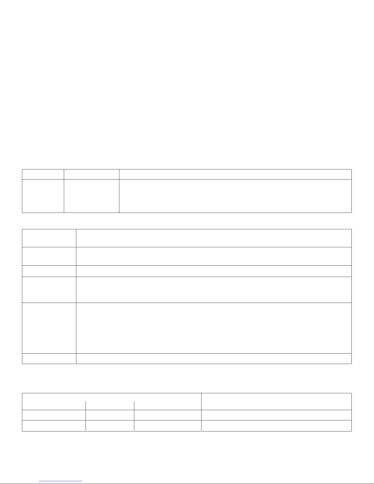
LED Diagnostics:
Red (DC) Green (AC) Power Supply Status
ON ON Normal operating condition.
ON OFF Loss of AC, Stand-by battery supplying power.
OFF ON No DC output.
OFF OFF Loss of AC. Discharged or no stand-by battery. No DC output.
Terminal Identification:
Terminal Function/Description
Legend
L, G, N Connect 115VAC/230VAC to these terminals:
Lto Hot, N to Neutral, G to ground (if used).
– DC + 12VDC / 24VDC @ 2.5 amp continuous non-power limited output.
*AC FAIL Indicates loss of AC power, e.g. connect to audible device or alarm
NC, C, NO panel. Relay normally energized when AC power is present.
Contact rating 1 amp @ 120VAC / 28VDC.
*Low Battery Indicates low battery condition, e.g. connect to alarm panel.
NC, C, NO Relay normally energized when DC power is present.
Contact rating 1 amp @ 120VAC / 28VDC
Low battery threshold:
12VDC output threshold set @ approximately 10.5VDC,
24VDC output threshold set @ approximately 21VDC.
– BAT + Stand-by battery connections. Maximum charge rate .5 amp.
*Note: Supervised models only
PD4/PD4CB/PD8/PD8CB/PD16W/PD16WCB - Power Distribution Module
Terminal Legend Function/
PD4/PD4CB PD8/PD8CB PD16W/PD16WCB Description
1P to 4P 1P to 8P 1P to16P Positive DC power outputs.
1N to 4N 1N to 8N 1N to 16N NegativeDC power outputs.
SMP3CTXseries -3-
L G N
OFF ON
OPEN - 24VDC
CLOSED - 12VDC
5A 250V
Power
Distribution
Module(s)
Power Supply
Board
CAUTION: De-energize unit prior to servicing.
Green
Lead
Wire
Strap
(from
Enclosure
to Door)
115/230VAC
power
mains
INPUT
CAUTION: When power supply board is set for 12VDC use only one (1) 12VDC
stand-by battery.
12VDC Rechargeable Battery
(optional)
12VDC Rechargeable Battery
(optional)
LOW BAT
NC C NO NC C NO
AC FAIL
LOW BAT
NC C NO NC C NO
AC FAIL
--- BAT + --- DC +
OPEN - 24VDC
CLOSED - 12VDC
INPUT
LED
1P, 2P,3P, 4P = FUSED OUTPUTS
1N, 2N, 3N, 4N = COMMON OUTPUTS
F1
F1
F2 F3 F4
COMMON POWER OUTPUTS
1P 1N 2P 2N 3P 3N 4P 4N
DC Output to devices From Power Supply
Board
(Factory Installed)
Used on
PTC Models
N
COMMON POWER OUTPUTS
P
FUSED POWER OUTPUTS
1 2 3 4 5 6 7 8
1
D1
INPUT
R1 LED
DC Output to devices From Power Supply
Board
(Factory Installed)
ON OFF
SW1
Fig. 1
Fig. 2
Fig. 3
Fig. 1a
Fig. 1b
Power Distribution Module(s):
common
outputs
protected
outputs
P
N
NPS
XFMR Input
12345678
9 10 11 12 13 14 15 16
PN
3.5A 250V
For continuous protection against risk of fire
replace fuses with same type and rating.
Used on
PTC Models
Fig. 4
-4- SMP3CTXseries
Altronix is not responsible for any typographical errors. Product specifications are subject to change without notice.
Altronix Corp.
140 58th Street, Brooklyn, New York 11220 USA, 718-567-8181, fax: 718-567-9056
web site: www.altronix.com, e-mail: [email protected], Made in U.S.A.
IISMP3CTX series - Rev.051105 H02J
12.230"
15.500"
1.100"
0.910"
1.100"
0.910"
0.790"
1.100"
1.500"
1.250"
5.000"
1.250"
1.500"
4.615"
4.615"1.500"
1.750"
1.500"4.615"
4.615"1.500"
1.750"
4.500"
4.500"
1.250"
1.500"
5.000"
2.000"
2.000"
1.250"
1.375"
1.125"
Enclosure Dimensions for:
•SMP3PMCTXX
15.5”H x 12.23”W x 4.5”D
Enclosure accommodates up to
two(2) 12VDC/12AH batteries.
Enclosure Dimensions for:
• SMP3CTX
• SMP3PMCTX
• SMP3PMP4
• SMP3PMP4CB
• SMP3PMP8
• SMP3PMP8CB
•SMP3PMP16
•SMP3PMP16CB
13.5”H x 13”W x 3.25”D
Enclosure accommodates up to
two (2) 12VDC/7AH batteries.
Also available to accommodate up to
two (2) 12VDC/12AH batteries
(please contact Altronix).
MEMBER
5.10"
6.5625"
3.25"3.25"
5.10"
5.10"
3.25"
1.00"10.50"1.00"
1.00" 1.00"
1.40"
1.20"
1.40"
1.20"
0.75"0.75" 11.00"
12.50"
3.25"
0.9375"
0.9375"
1.40" 4.85" 4.85" 1.40"
1.20"
Bottom
Top
RightLeft

This manual suits for next models

9

Other Altronix Power Supply manuals

Altronix ALTV244UL Operating and maintenance instructions

Altronix

Altronix ALTV244UL Operating and maintenance instructions

Altronix ALTV244UL User manual

Altronix

Altronix ALTV244UL User manual

Altronix OLS250 User manual

Altronix

Altronix OLS250 User manual

Altronix OLS120D2X User manual

Altronix

Altronix OLS120D2X User manual

Altronix AL201UL User manual

Altronix

Altronix AL201UL User manual

Altronix SMP10 User manual

Altronix

Altronix SMP10 User manual

Altronix ALTV615DC8220 Operating and maintenance instructions

Altronix

Altronix ALTV615DC8220 Operating and maintenance instructions

Altronix ALTV248ULCB Operating and maintenance instructions

Altronix

Altronix ALTV248ULCB Operating and maintenance instructions

Altronix VertiLine24 Series User manual

Altronix

Altronix VertiLine24 Series User manual

Altronix AL624E Service manual

Altronix

Altronix AL624E Service manual

Altronix Maximal11FDV User manual

Altronix

Altronix Maximal11FDV User manual

Altronix AL125220 User manual

Altronix

Altronix AL125220 User manual

Altronix WayPoint562 User manual

Altronix

Altronix WayPoint562 User manual

Altronix TROVE T1SAK34D User manual

Altronix

Altronix TROVE T1SAK34D User manual

Altronix SAV Series User manual

Altronix

Altronix SAV Series User manual

Altronix AL175UL User manual

Altronix

Altronix AL175UL User manual

Altronix eFlow Series User manual

Altronix

Altronix eFlow Series User manual

Altronix ALTV615DC Series User manual

Altronix

Altronix ALTV615DC Series User manual

Altronix SMP3CTX Series User manual

Altronix

Altronix SMP3CTX Series User manual

Altronix AL1012ULXB Service manual

Altronix

Altronix AL1012ULXB Service manual

Altronix WayPoint307A User manual

Altronix

Altronix WayPoint307A User manual

Altronix Vertiline8 User manual

Altronix

Altronix Vertiline8 User manual

Altronix SMP10C24X220 Series User manual

Altronix

Altronix SMP10C24X220 Series User manual

Altronix AL400UL User manual

Altronix

Altronix AL400UL User manual

Popular Power Supply manuals by other brands

Akyga AK-TB-33 user manual

Akyga

Akyga AK-TB-33 user manual

Procon NP-9615 SERIES user manual

Procon

Procon NP-9615 SERIES user manual

Corsair AX Series manual

Corsair

Corsair AX Series manual

AimTTi QPX1200S instruction manual

AimTTi

AimTTi QPX1200S instruction manual

I-Tech IT7300 Series Programming guide

I-Tech

I-Tech IT7300 Series Programming guide

Meanwell RSP-2400-12 manual

Meanwell

Meanwell RSP-2400-12 manual

Corsair CX-M Series manual

Corsair

Corsair CX-M Series manual

Meanwell HEP-1000 installation manual

Meanwell

Meanwell HEP-1000 installation manual

TREX Fuel Tank Chameleon user manual

TREX

TREX Fuel Tank Chameleon user manual

Unit UDP6722 user manual

Unit

Unit UDP6722 user manual

Delta PMC-24V100W1AB instruction manual

Delta

Delta PMC-24V100W1AB instruction manual

I-Tech IT6720 user guide

I-Tech

I-Tech IT6720 user guide

Delta PCM-48V600W1B Series instruction manual

Delta

Delta PCM-48V600W1B Series instruction manual

Delta PMT2 150 W Series Technical data sheet

Delta

Delta PMT2 150 W Series Technical data sheet

KEPCO TBC Series instruction manual

KEPCO

KEPCO TBC Series instruction manual

Delta PMT-36V350W1A Series Assembly & installation

Delta

Delta PMT-36V350W1A Series Assembly & installation

Tripp Lite SMARTONLINE SUPDU001 owner's manual

Tripp Lite

Tripp Lite SMARTONLINE SUPDU001 owner's manual

Isotech IPS1820D manual

Isotech

Isotech IPS1820D manual

manuals.online logo
manuals.online logoBrands
  • About & Mission
  • Contact us
  • Privacy Policy
  • Terms and Conditions

Copyright 2025 Manuals.Online. All Rights Reserved.