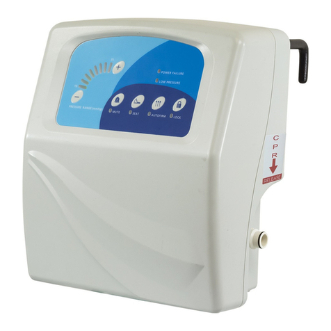
ALTUS Clio User manual

Technology Workstation Solutions — Powered
O
peratin
g
Manual
then
charge
it.
deploy
it.
August 2018

Technology Workstation Solutions — Powered
2 ALTUS | 3731 Northridge Dr, NW |Suite 1 |Walker, MI 49544 |T: 888.537.1311 Iwww.altus-inc.com | AS-1584_Rev.H
Table of Contents
Table of Contents
T
able o
f
C
ontent
s
Table of Contents
S
ummar
y
o
f
Warnin
gs
........................................................................................
3
Product Introductio
n
...........................................................................................
4
K
e
y
board Plat
f
orm Ad
j
ustment
...........................................................................
5
C
able Mana
g
ement
............................................................................................
6
L
aptop
S
tand
......................................................................................................
7
Accessor
y
Installation instruction
s
...................................................................
8
-
9
C
har
g
in
g
Unit
....................................................................................................
10
Power
Sy
stem
O
verview
.............................................................................
1
1-12
B
atter
y
&
Power
Sy
stem Removal
/
Installatio
n
............................................
13
-1
6
B
asic Troubleshootin
g
.................................................................................
1
7-24
Warrant
y
......................................................................................................
26
-2
6
Make sure
y
our cart workstation U
S
B port is connected to the U
S
B port on the
MPM Power unit
/
controller installed in
y
our cart. Download the Powervar
MPM View install packa
g
e, and save it to the workstation desktop
(
or other
c
onvenient location
)
.
T
o download the latest so
f
tware
g
o to: http://connectivity.powervar.com/mpm/download.asp.
S
elect “Install MPMView
(
Windows XP
/
Windows 7
)
” to download.

3 ALTUS | 3731 Northridge Dr, NW |Suite 1 |Walker, MI 49544 |T: 888.537.1311 Iwww.altus-inc.com | AS-1584_Rev.H
S
ummar
y
o
f
Warnin
gs
Please read all parts o
f
this
g
uide. When set-up is complete, do not discard
g
uide.
Please
fi
le
g
uide in secure place
f
or
f
uture re
f
erence.
Appropriate air
fl
ow is required
f
or this unit to operate correctl
y
under normal and
f
ault conditions.
C
omplies with requirements
f
or U
S
f
or outside the patient environment.
O
nl
y
authorized personnel, experienced in servicin
g
electrical equipment should open the power s
y
stem.
DO
N
O
T operate the power s
y
stem without the covers completel
y
installed and the connectors attached properl
y
. The covers
p
rovide sa
f
et
y
f
rom potentiall
y
dan
g
erous volta
g
es.
D
o not connect or disconnect the s
y
stem while power is applied. Do not open or in an
y
other manner chan
g
e the access to
the internal portion o
f
the s
y
stem while power is applied.
D
o not allow the s
y
stem to come in contact with
fl
uids. Do not operate the s
y
stem i
f
wet.
T
he supplied spiral cord is rated
f
or medical use.
C
onnectin
g
the cord to an outlet that is not medical
g
rade
(
indicated with
g
reen dot
)
will not ensure
g
roundin
g
protectio
n
S
ipral cord, power s
y
stem and cart are
f
or IND
OO
R use onl
y
. D
O
N
O
T
O
PERATE
O
UTD
OO
R
S
.
Inspect spiral cord be
f
ore each use. D
O
N
O
T U
S
E
CO
RD IF DAMA
G
ED.
DO
N
O
T plu
g
more than the speci
fi
ed number o
f
watts into spiral card cord.
DO
N
O
T run spiral cord throu
g
h doorwa
y
s or across walls or
fl
oors.
F
ull
y
insert certi
fi
ed detachable spiral cord plu
g
into outlet. D
O
N
O
T unplu
g
b
y
pullin
g
on cord. For 250VA models, a t
y
pe not
l
i
g
hter than
S
JT 18AW
G
should be used.
DO
N
O
T remove, bend or modi
fy
an
y
metal pron
g
s or pins o
f
spiral card cord.
DO
N
O
T u
s
e exce
ss
ive
f
orce to make connection
s
.
K
eep spiral cord awa
y
f
rom water. D
O
N
O
T PLU
G
CO
RD INT
O
O
UTLET IF WET.
K
eep children awa
y
f
rom spiral cord.
DO
N
O
T ALL
O
W
CO
RD T
O
O
VERHEAT.
DO
N
O
T drive, dra
g
or place ob
j
ects over spiral cord. Do not stand or walk on spiral cord.
B
reakin
g
the seal on the batter
y
to add water will dama
g
e the batter
y
and could cause in
j
ur
y
.
B
atter
y
warrant
y
is automaticall
y
void when a
f
ull
y
dischar
g
ed batter
y
is le
f
t in an unused state
f
or more than three
(
3
)
c
onsecutive da
y
s.
T
he power s
y
stem is desi
g
ned
f
or power cart mounted equipment onl
y
. D
O
N
O
T connect equipment that is not mounted
o
n the cart into the power s
y
stem outlets. D
O
N
O
T connect cart mounted equipment directl
y
into a power source that is not
mounted to the cart. D
O
N
O
T di
s
a
ss
emble the MP
M
Technology Workstation Solutions — Powered
T
ransportation
/S
tora
g
e
S
tore this s
y
stem within a
temperature ran
g
e of 32˚F - 90˚F
(
0˚C - 32˚C
)
; Pressure 500 hPa to
1
060 hPA; Humidit
y
20
%
RH to
9
5
%
RH non-condensin
g
.
L
ithium Iron Phosphate
(
LiFe
)
Batter
y
Disposal
B
atter
y
rec
y
clin
g
is encoura
g
ed.
D
ispose o
f
in accordance with
l
ocal, state and
f
ederal laws
and re
g
ulations.
C
art Disposal
T
o dispose o
f
this cart usin
g
the local
g
uidelines and
r
e
g
ulations
f
or waste.
Plea
s
e contact Altu
s
C
u
s
tomer
S
ervice
f
or in
f
ormation:
1
.
888
.
5
27.1
3
1
1
S
ealed Lead Acid
B
atter
y
must be
r
ec
y
cled.

4 ALTUS | 3731 Northridge Dr, NW |Suite 1 |Walker, MI 49544 |T: 888.537.1311 Iwww.altus-inc.com | AS-1584_Rev.H
Product Introductio
n
Standard Features:
1
. Hei
g
ht Ad
j
ustment
C
olum
n
2
. Hi
g
hl
y
Mobile 4”
/
100mm
S
in
g
le-Wheel
S
hrouded
C
aster
s
3. Hei
g
ht Ad
j
ustment Hand Lever
4
. Handle
5
. Lar
g
e Thermo
f
oil
Work
s
ur
f
ace Area
6. Ke
y
board Plat
f
or
m
7
. Mousin
g
Area
8
. Inte
g
rated Bar
C
ode Holder
9
. L
C
D Monitor
S
upport
10
. R
U
I
1
1. Power
Sy
stem
&
Batter
y
C
ompartment
1
2. Internal Technolo
gy
&
C
able Mana
g
ement
13
.
3
-
O
utlet Power
C
ord
(
not shown
)
1
4.
C
oiled Power
C
ord Holder
1
5. Batter
y
Access Panel
(
back
)
1
6. Up
/
Down Button
S
witch
7
914
11
15
6
4
3
4
5
2
1
Technology Workstation Solutions — Powered
12
13
13
8
15
14
10
9
12
12
12
13
9
8
16

5 ALTUS | 3731 Northridge Dr, NW |Suite 1 |Walker, MI 49544 |T: 888.537.1311 Iwww.altus-inc.com | AS-1584_Rev.H
K
e
y
board Plat
f
or
m
Ad
j
ustment Instruction
s
Technology Workstation Solutions — Powered
T
he ke
y
board plat
f
orm is tilted and stored
at 90 de
g
rees
f
or shippin
g
purposes onl
y
(S
ee Fi
g
. A
)
.
T
o u
s
e:
Place both hand
s
on each
s
ide o
f
the
k
e
y
board plat
f
orm and simpl
y
tilt to desired
p
osition and slide-out
f
or use
(S
ee Fi
g
. B
)
.
1
2A
B

6 ALTUS | 3731 Northridge Dr, NW |Suite 1 |Walker, MI 49544 |T: 888.537.1311 Iwww.altus-inc.com | AS-1584_Rev.H
Wired Ke
y
board and Mousin
g
Routin
g
In
s
tallation In
s
truction
s
Technology Workstation Solutions — Powered
T
he ke
y
board plat
f
orm and mouse tra
y
are
equipped with wire mana
g
ers t
o
k
eep wires in place
(S
ee Fi
g
. A
)
K
e
y
board and Mouse Wire Mana
g
ement
to inside o
f
technolo
gy
stora
g
e area
F
eed both ke
y
board and mouse wires
throu
g
h access hole, located under the
h
andle
(S
ee Fi
g
. B
)
.
Inside o
f
technolo
gy
stora
g
e area
O
nce cables are throu
g
h hole,
p
ull throu
g
h
(S
ee Fi
g
.
C)
. Auxiliar
y
h
oles
(S
ee Fi
g
.
C)
.
1
2
K
e
y
board and Mouse Wire Mana
g
ement
A
C
B
B
C

7 ALTUS | 3731 Northridge Dr, NW |Suite 1 |Walker, MI 49544 |T: 888.537.1311 Iwww.altus-inc.com | AS-1584_Rev.H
Technology Workstation Solutions — Powered
1
2
3
4
O
pen sur
f
ace.
Remove “
g
reen” shippin
g
tape
(
located in
4
locations
)
f
rom Laptop
S
tand.
Remove Laptop
S
tand.
T
o install all cable into laptop, make sure
that all cables are attached to laptop
fi
rst
then connect to appropriate connection
s
w
ithin the
C
lio technolo
gy
stora
g
e area.
When all o
f
cables are mana
g
ed, place
L
aptop
S
tand back into holes in
stora
g
e area.
La
p
to
p
S
tan
d
C
lio Laptop
S
tand
(O
nl
y
on
C
1 Model
)
1
2
4

8 ALTUS | 3731 Northridge Dr, NW |Suite 1 |Walker, MI 49544 |T: 888.537.1311 Iwww.altus-inc.com | AS-1584_Rev.H
Technology Workstation Solutions — Powered
1
2
3
4
5
5
O
pen
f
ront sur
f
ace.
Place Flat
S
creen Monitor
S
upport
throu
g
h the
(
2
)
holes in the rear work
sur
f
ace assembl
y
.
Attach
(
2
)
5
/
16-18” Flan
g
e Hex Nuts to bolts
underneath the rear work sur
f
ace assembl
y
.
T
i
g
hten with 1
/
2”
S
ocket Wrench
(
pre
f
erred
)
o
r disposable 1
/
2” wrench
(
included
)
.
T
o mana
g
e cables within the Flat
S
creen
Monitor
S
upport, remove back cable
mana
g
ement cover.
T
o remove back cable mana
g
ement
c
over, remove 8-32 x 3
/
4” screw.
D
o not di
s
card.
1
2
3
Internal
C
able Mana
g
ement
B
ack
C
able
Mana
g
ement
C
over
F
lat
S
creen
Monitor
S
upport
8
-
3
2 x
3/
4”
S
crew
Adjustment Knob
F
lat
S
creen
Monitor
S
upport
C
lio Work
s
ur
f
ace and L
C
D
Monitor
S
upport

9 ALTUS | 3731 Northridge Dr, NW |Suite 1 |Walker, MI 49544 |T: 888.537.1311 Iwww.altus-inc.com | AS-1584_Rev.H
Technology Workstation Solutions — Powered
i
ncluded
(
4
)
Phillips Drive Flat Head
Machine
S
crew
s
.
C
hoose len
g
th o
f
screw b
y
the depth
of
mountin
g
location on back o
f
monitor.
I
f
too lon
g
o
f
screw is used, dama
g
e t
o
monitor ma
y
occur.
Mana
g
in
g
monitor cables:
O
nce monitor is attached. Ad
j
ust
monitor to its hi
g
hest position.
Mana
g
e cables
f
rom monitor down
and throu
g
h cable mana
g
ement hole.
R
einstall back cover
(
Make sure to
r
oute the cables throu
g
h the side
access holes in cable mana
g
ement
c
over
)
. Ali
g
n screw hole in cover
w
ith
s
crew bo
ss
.
Us
e
8
-
3
2 x
3/
4”
L
on
g
Pan Head Machine
S
crew to
f
a
s
ten cover and Rein
s
tall
Ad
j
ustment Knob.
N
O
TE:
F
or monitor hei
g
ht ad
j
ustment,
make sure the ad
j
ustment knob is
sli
g
htl
y
loosened
(
Do not loosen
all the wa
y)
.
F
or monitors wei
g
hin
g
more than
1
0 lbs., ti
g
hten the ad
j
ustment knob
w
hen monitor is at desired hei
g
ht.
6
7
8
9
8
7
6
C
able Access Holes
(
2
)
V
E
S
A Plate
C
able Mana
g
ement Hole
Routed
C
able
s
8
-
3
2 x
3/
4”
S
crew
Ad
j
ustment Knob
8
-
3
2 x
3/
4”
S
crew
C
lio Work
s
ur
f
ace and L
C
D
Monitor
S
upport

10 ALTUS | 3731 Northridge Dr, NW |Suite 1 |Walker, MI 49544 |T: 888.537.1311 Iwww.altus-inc.com | AS-1584_Rev.H
Monitor
S
u
pp
ort Installation Instructions
Technology Workstation Solutions — Powered
1
2
3
Internal
C
able Mana
g
ement
Attach Monitor to Monitor Tilt Bracket.
Po
s
ition the Monitor Tilt Bracket
a
s
s
hown.
S
tart the
3
Pem
S
tud
s
(
located on the back o
f
bracket
)
i
nto the
3
hole
s
on the
f
ront o
f
the
C
omponent Housin
g
(
there are
two di
ff
erent hei
g
hts; hi
g
h and low
)
.
S
ecure Monitor Tilt Bracket usin
g
3 Win
g
Nuts.
Mana
g
e cables within
C
omponent
Housin
g
(
le
f
t or ri
g
ht cable
mana
g
ement holes
)
.
(
Hi
g
h and Low
)
Monitor Tilt
B
racket
Monitor Tilt
B
racket
Monitor
Component
H
ousin
g
C
able
Mana
g
ement
H
ole
s
(
3
)
Win
g
Nut
s
w
ith Tiltin
g
Monitor
S
upport
(O
nl
y
on
C
6 Model
)

O
nce cart is
f
ull
y
set up with all electronic devices, it should be plu
gg
ed into a medical
g
rade outlet.
T
he cart should
f
ull
y
char
g
e be
f
ore deplo
y
in
g
(
Note: All carts are shipped with a 30
%
char
g
e. I
f
storin
g
i
n warehouse be
f
ore deplo
y
in
g
, char
g
e
f
ull
y)
.
While the cart is char
g
in
g
, the LED on the power s
y
stem
external user inter
f
ace will
fl
ash until the batter
y
is 100
%
f
ull.
F
or LiFe Batteries: Allow up to 2 hours to
f
ull
y
char
g
e.
F
or
S
LA Batteries: Allow up to 5 hours to
f
ull
y
char
g
e.
T
estin
g
Your
C
art
T
o test
y
our cart
f
or power, the unit needs to be turned on. To do so,
p
ress and hold the power button on the power s
y
stem user inter
f
ace
f
or approximatel
y
2 seconds.
T
he power s
y
stem will beep and the
f
ar le
f
t LED li
g
ht will turn on. At this point, all powered devices
c
onnected to the outlet strip should receive power.
O
nce on, the LED Ke
y
board li
g
ht ma
y
be used.
Press to turn li
g
ht on
/
o
ff
. The LED Ke
y
board li
g
ht has a 5 minute timeout
f
unction
j
ust in case the
l
i
g
ht was not turned o
ff
b
y
the operator.
Note: Monitors, laptops and other devices will need to be manually turned on.
S
o
f
tware Pre-In
s
tallation
/
In
s
tallation Note:
T
o download the latest so
f
tware
g
o to: http://connectivity.powervar.com/mpm/download.asp.
D
ouble-click the MPM View in
s
taller icon to
s
tart the in
s
tall. MPM View will
automaticall
y
detect the MPM power unit attached to the P
C
workstation U
S
B port.
11 ALTUS | 3731 Northridge Dr, NW |Suite 1 |Walker, MI 49544 |T: 888.537.1311 Iwww.altus-inc.com | AS-1584_Rev.H
C
har
g
in
g
Your
C
art
Technology Workstation Solutions — Powered

12 ALTUS | 3731 Northridge Dr, NW |Suite 1 |Walker, MI 49544 |T: 888.537.1311 Iwww.altus-inc.com | AS-1584_Rev.H
Power
Sy
stem
O
verview
Clio External User Interface
T
he eas
y
-to-read batter
y
user inter
f
ace, which is located on the
f
ront sur
f
ace o
f
the cart handle,
g
ives the user a
r
eal-time status o
f
the batter
y
. Each LED will illuminate in several sequences to indicate the approximate char
g
e
l
evel o
f
the batter
y
.
•
T
he
fi
rst LED displa
y
s power on
/
o
ff
indicator
•
L
EDs two throu
g
h
fi
ve indicate char
g
e level and correspond to a percent o
f
char
g
e ran
g
e.
• Power Button
(
third to last button on ri
g
ht
)
- To power up, press and hold
f
or 2 seconds, and the on
/
o
ff
Indicator will beep and power on.
To power down, press and hold
f
or 2 seconds, and the on
/
o
ff
Indicator will beep and power o
ff
.
• Power Alert Mute Button
(
second to last button on ri
g
ht
)
- I
f
the batter
y
level
f
alls below 10
%
f
or LiFe Batter
y
an alarm will
s
ound. Thi
s
button will mute the alarm.
•
K
e
y
board LED Li
g
ht
(
last button on ri
g
ht
)
- To turn on, press button. The li
g
ht will automaticall
y
turn o
ff
a
f
ter
5 minutes or i
f
button is pressed a
g
ain.
Using the Power System
T
urnin
g
O
n
Sy
ste
m
T
urnin
g
Off
Sy
ste
m
Mute Button
Us
e
Press and hold power butto
n
f
or approximatel
y
3 second
s
Press and hold power butto
n
f
or approximatel
y
3 second
s
Pre
ss
and hold until audible alar
m
d
i
s
continue
s
F
uel
G
au
g
e
/
Power
Sy
ste
m
w
ill beep. The LED on the
l
e
f
t side turns
g
reen. All
c
omponents will receive power.
F
uel
G
au
g
e
/
Power
Sy
stem will beep.
L
ED on le
f
t
s
ide will turn o
ff
.
I
f
Power
Sy
stem is plu
gg
ed in, the
o
ther LED li
g
hts will remain lit to show
b
atter
y
level.
All components will N
O
T receive power.
F
uel
G
au
g
e
/
Power
Sy
stem will beep.
Audible alarm will silence as lon
g
a
s
b
atter
y
level is above 10
%
. Whe
n
at 10
%
, the alarm, even i
f
muted, will
r
esound ever
y
minute. Action to take
i
s to char
g
e the batter
y
or shut down
the unit.
U
se this durin
g
:
•
Initial start-up
•
A
f
ter replacin
g
batter
y
•
I
f
s
y
stem has been shut dow
n
•
I
f
s
y
stem has shut itsel
f
dow
n
a
f
ter reachin
g
low batter
y
level
U
se this durin
g
:
•
I
f
cart will not be used or plu
gg
ed in
f
or
an extended period o
f
time
•
Be
f
ore replacin
g
batter
y
•
I
f
Power
Sy
stem will be service
d
U
se this durin
g
:
•
When the audible alarm
fi
rst
g
oe
s
o
ff
at the 20
%
batter
y
level
remainin
g
. When alarm sounds
,
plu
g
in cart to avoid dama
g
e
to batter
y
.
Technology Workstation Solutions — Powered
On/Off
Indicator
Battery Charge
Level
Mute
Button
Power
Button
Keyboard
LED Light

13 ALTUS | 3731 Northridge Dr, NW |Suite 1 |Walker, MI 49544 |T: 888.537.1311 Iwww.altus-inc.com | AS-1584_Rev.H
Power
Sy
stem
O
verview
C
ontinue
d
Technology Workstation Solutions — Powered
L
ED Position 1
(
Power
O
n
/Off)
S
olid
G
reen -
Sy
stem is on and all components will receive power.
No Li
g
ht -
Sy
stem is turned o
ff
. I
f
cart is plu
gg
ed in, unit can still be char
g
ed.
L
ED Position 2-5
(C
har
g
in
g
Level
)
F
lashin
g
Red - Less than 5
%
batter
y
li
f
e remainin
g
. Plu
g
in unit
i
mmediatel
y
.
F
lashin
g
Yellow - Less than 10% batter
y
life remainin
g
.
Plu
g
in unit as soon as possible.
S
olid
G
reen - Batter
y
is at least 90-100
%
char
g
ed.
C
omponent should
still be plu
gg
ed in when possible to maximize batter
y
li
f
e.
F
lashin
g
G
reen - Each LED
fl
ashin
g
g
reen re
fl
ects the level o
f
char
g
e
achieved durin
g
rechar
g
in
g
.
No Li
g
ht - Power
Sy
stem is turned o
ff
or batter
y
is not properl
y
c
onnected to the power s
y
stem.
L
ED Position 5
(
Char
g
in
g
Status when plu
gg
ed into wall outlet
)
S
olid
G
reen - Batter
y
is
f
ull
*
Batter
y
Low:
LED 2 Flashin
g
Yellow
O
N
f
or 1 second,
O
FF
f
or 1 second. Buzzer should beep once
per second, until silenced b
y
pressin
g
“Alarm Mute button.
**
Batter
y
Low
C
ritical
When
S
tate o
f
C
har
g
e level
f
alls below
6
%
, LED 2 will
fl
ash RED 1
/
2 second
O
N,
1
/
2 second
O
FF. Buzzer will beep 2X each
second - until silenced b
y
pressin
g
“Allarm Mute” button.
***O
utput
O
n LED Behavior
LED 1 is on when output is on and o
ff
when output is o
ff
.

14 ALTUS | 3731 Northridge Dr, NW |Suite 1 |Walker, MI 49544 |T: 888.537.1311 Iwww.altus-inc.com | AS-1584_Rev.H
B
atter
y
Removal and Replacement
O
nl
y
use batteries speci
fi
ed b
y
ALTU
S
. Failure to
do so will void the power s
y
stem warrant
y
.
C
all cu
s
tomer
s
ervice
f
or
f
urther detail
s
.
Do not replace batter
y
in ox
yg
en rich environments
sparkin
g
ma
y
occur.
Alwa
y
s unplu
g
the power cord
f
rom the wall outlet
when removin
g
the batter
y
.
Battery Removal
T
ool
s
Needed: 1
/8
” Allen Wrench
S
tep 1: Power Down
Sy
ste
m
A. Turn o
ff
an
y
components plu
gg
ed into cart
B. Turn o
ff
Power
Sy
stem b
y
Holdin
g
O
n
/Off
Button
f
or 2
s
econd
s
S
tep 2: Lon
g
-term
S
tora
g
e
(
more than 2 months
)
Warnin
g
: I
f
cart will not be used
f
or more tha
n
2 months, turn o
ff
the cart b
y
holdin
g
the
O
N
/O
FF
Button. The batter
y
will need to be rechar
g
e
d
ever
y
30 da
y
s to prevent dama
g
e.
S
tep 3: Remove back access panel b
y
loosenin
g
and removin
g
(
2
)
screws
(S
ee Fi
g
A
)
.
S
tep 4: Remove back panel. Remove strap and slide
batter
y
f
rom base
(S
ee Fi
g
. B
)
S
tep 5: To access batter
y
cable
(
to disconnect
f
rom controller
)
loosen and remove
(
2
)
screws
f
rom the
f
ront panel
o
f
base
(S
ee Fi
g
.
C)
S
tep 6: Disconnect batter
y
harness
f
rom controller.
(S
ee Fi
g
. D
)
Technology Workstation Solutions — Powered
R
emove
S
trap
(
Fi
g
. B
)
D
i
s
connect Yellow
B
atter
y
Harnes
s
(
Fi
g
. D
)
(
2
)
S
crews on both side
s
(
Fi
g
.
C)
(
Fi
g
A
)
(
2
)
S
crew
s
(
Batter
y
terminals
)
L
ocated in back on A
s
cend EL

15 ALTUS | 3731 Northridge Dr, NW |Suite 1 |Walker, MI 49544 |T: 888.537.1311 Iwww.altus-inc.com | AS-1584_Rev.H
B
atter
y
Removal and Replacement
Technology Workstation Solutions — Powered
Battery Removal Continued
S
tep 7: Disconnect “blue” RJ45 cable
f
rom controller.
(S
ee Fi
g
. E
)
. I
f
replacin
g
with a
S
LA batter
y
,
this step is not needed.
I
f
blue RJ45 cable cannot be accessed, the
controller can be removed b
y
loosenin
g
and
removin
g
(
2
)
screws
(S
ee Fi
g
, F
)
.
O
nce screws
are removed, simple slide controller out and
di
s
connect Blue R
J
4
5
cable
f
rom
s
lot.
(
Note slot location
f
or new batter
y
cable
)
.
S
tep 8: Replace with new batter
y
and repeat
S
teps 1-
7
in rever
s
e order. Make
s
ure all connection are
secure
(
“clickin
g
” them in place
)
.
“Blue” R
J
4
5
C
able
(
Fi
g
. E
)
(
2
)
S
crews - Phillips drive
S
lide out controller in
A
s
cend EL
C
art
s
(
Fi
g
. F
)

16 ALTUS | 3731 Northridge Dr, NW |Suite 1 |Walker, MI 49544 |www.altus-inc.com | AS-1584_Rev.H
B
atter
y
and Power
Sy
stem Removal and Replacement
DO
N
O
T
CO
NNE
C
T THI
S
U
NIT T
O
BATTERIE
S
N
O
T
SU
PPLIED BY ALT
US
WITH
OU
T VERIFYIN
G
CO
NTR
O
LLER
S
ET
U
P AND
O
THER
O
PTI
O
N
S
WITH ALT
US
.
WARNING!
I
f
replacin
g
the LiFe
(
Lithium Iron Phosphate
)
batter
y
with a
S
LA batter
y
or
S
LA to LiFe,
the
f
ollowin
g
steps need to be completed. I
f
the MPM so
f
tware has been installed, this will help
w
ith ste
p
#
4
.
1
. All cables to and
f
rom controller must be connected, includin
g
the batter
y
and its cables and connections.
Both the A
C
-In and A
C
-out connector ends include a lockin
g
f
eature to prevent
f
rom pullin
g
apart. To disconnect pull back
both “red” tab
s
.
N
ote:
O
lder models ma
y
not have this
f
eature
(
red tabs
)
so simpl
y
disconnect
.
C
ontroller mu
s
t
fi
r
s
t be
O
FF
(
no li
g
hts on the Remote User Inter
f
ace
)
and connected into A
C
power.
I
f
usin
g
the MPM
S
o
f
tware use this step. I
f
not, proceed to step 2.
C
onnect the U
S
B cable into the technolo
gy
component within the cart
(
or into a resident laptop with
the MPM so
f
tware loaded
)
.
2
. Wait
f
or the double
y
ellow to appear on the inter
f
ace.
3. When this happens, press and hold the mute button
f
or 5 seconds.
O
ne “beep” will be made immediatel
y
.
Within 3-5 seconds a
f
ter the initial “beep”, a second “beep” will be heard.
Keep holdin
g
down the mute button until a scrollin
g
li
g
ht sequence appears
(
release mute button at this time
)
.
This will look like all o
f
the
g
reen LED li
g
hts
g
oin
g
li
g
htin
g
up in order and then back o
ff
in order. When
g
reen li
g
ht
sequence is complete, the controller will show a Yellow LED and
G
reen LED and then will shut itsel
f
o
ff
(
all li
g
hts
will turn o
ff)
and then will “Reboot” itsel
f
. When controller reboots, the remote user inter
f
ace will show the batter
y
level o
f
the connected batter
y
.
4
. The “batter
y
readin
g
f
or con
fi
rmation” will onl
y
be available i
f
MPM View is bein
g
utilized.
The cart is read
y
to be used.
Technology Workstation Solutions — Powered
No Li
g
ht
s
US
B

17 ALTUS | 3731 Northridge Dr, NW |Suite 1 |Walker, MI 49544 |T: 888.537.1311 Iwww.altus-inc.com | AS-1584_Rev.H
T
roubleshootin
g
Technology Workstation Solutions — Powered
Diagnostics & Troubleshooting
Thissectionincludesabrieftroubleshootingtableandthecompletelistof
EventsandconditioncodesthatareloggedanddisplayedinMPMView
Troubleshooting
Thetroubleshootinginformationprovidedinthissectionshouldhelpyou
discoverthecauseofmostcommonlyencountereddifficulties.Beforefollowing
thetroubleshootingstepsprovided,becertainthat
otheMPMisconnectedtoaproperlyworkingoutlet,
othelinevoltagetotheMPMiswithinspecifiedboundaries
ProblemPossibleCause Actionyoushouldtake
MPMdoes
notpower
upandhas
noaudible
alarm
On/Offbuttonisnot
pressedlongenough
PressandholdtheOn/Offswitch
foratleast3seconds.
InvalidBatteryandInvalid
InputAC.
Checkwallsocketandtestfor
properlinevoltage.
MPMinputpowercordis
notpluggedin
Plugininputpowercord
Output fuseisopen
Reduceloadreplacefuseandtest
Backuptime
islessthan
expected
Batteryisnotfullycharged
orbatteryisdead.
Rechargebatteryforatleast24
hoursandretestbackuptime.
MPMis
normal,but
theloadwill
notturnon.
Loadinputpowercordis
looseornotconnected.
OutputFuseisblown.
Verifycomputerinputpower
cord
Verifyoutputwiringharness
withincartassembly
CheckOutputFuselocatedon
endofMPMunit.(seep.31)

18 ALTUS | 3731 Northridge Dr, NW |Suite 1 |Walker, MI 49544 |T: 888.537.1311 Iwww.altus-inc.com | AS-1584_Rev.H
T
roubleshootin
g
Technology Workstation Solutions — Powered
Events & Conditions
TheMPMwillindicatethepresenceofWarning(yellow)andSevere(red)
AlarmsandConditionsviatheRUIandviatheClinicViewtaskbarapplicationas
shownbelow.
ThespecificalarmthatisraisingtheYelloworRedindicatorwillbeloggedand
displayedlocallyintheTechViewapplication(taskbarapp,rightclick,Advanced)
oroverthenetwork(LAN)viaCIO/FleetViewapplication.
Thetablebelowliststhespecificalarmsandwhattheymean.
INDICATIONSDURINGNORMALPOWERSYSTEMOPERATION
CodeAsdisplayedin
MPMView
Asdisplayed
inRUILEDs
Whatitmeans
NoDisplay1stfuelgaugeLED
green,topfuel
gaugeledRed
USERACTION:None–normalstartupindication.
TechnicianNote:thechargerinverterispoweringup
NONE NormalOperation OutputACLED
greenoroff.One
ormorefuel
gaugeLED(s)
Green.
USERACTION:note“fuelgauge”LEDsonRUIorbatterycharge
levelandestimatedminutesavailableonMPMViewtaskbaricon.
BlinkinggreenfuelgaugeLEDindicatesbatteryrechargein
process
14Ͳ
054
BatteryRecharge
inprocess
24Ͳ
034
BatteryCharge
Threshold:Low
Bottomfuel
gaugeLEDYellow
USERACTION:“<3Ͳminutewarning”connectcartpowertoAC
soontorechargethebattery.
TechnicianNote:1stlevelwarningforlowbatterychargelevel,
triggeredwheneitherthresholdfor%chargeorestimatedminutes
isreached.Defaultthresholdsare10%or3minutes.
ThesesettingscanbemodifiedusingMPMTechViewsoftware.
34Ͳ
053
BatteryCharge
Threshold:LowͲ
Critical
Bottomfuel
gaugeLEDRed
USERACTION:batterynearlydepleted,connectcartpowertoAC
nowtorechargethebattery.
TechnicianNote:Finalwarningtorechargebattery–shutdown
imminent.HardcodedwithinMPMtosignalwhenchargelevelis
lessthan5%offullcapacity.

19 ALTUS | 3731 Northridge Dr, NW |Suite 1 |Walker, MI 49544 |T: 888.537.1311 Iwww.altus-inc.com | AS-1584_Rev.H
T
roubleshootin
g
Technology Workstation Solutions — Powered
CodeAsdisplayedin
MPMView
Asdisplayed
inRUILEDs
Whatitmeans
14Ͳ
070
Chargerisin
PreChargeMode
RUIwillblinkthe
4“fuelgauge”
LEDslowtohigh
ina“rolling
green”pattern
USERACTION:UsethecartonlywhenconnectedtoACpower.
Whenthealarmclears–notebatterychargestatebefore
disconnectingfromACpower.
TechnicianNote:PreChargeisaspecialchargeroperatingmode
designedtoreactivateaSmartLithiumbatteryinselfͲprotect
mode.
Thisalarmpresentsonstartupifallthreeconditionsaretrue:
1.)MPMisconfiguredforLithiumbattery
and2.)invalidbatteryterminalDCvoltagedetectedbytheMPM
and3.)thebatterycommunicatesitsstateasselfͲprotectmode,
ortherearenocommunicationswiththebattery.
Thechargerwillremaininthismodeforupto30minuteswaiting
anindicationthatthebatteryhasreturnedtonormalfunction.
After30minutes,thisconditionwillescalatetoayellowwarning
indicatingthatthebatteryneedsserviceattention.(See24Ͳ032
ServiceCheck:BatteryConnection).
14Ͳ
056
SmartBattery:
ReportsFull
Discharge
noneUSERACTION:None
TechnicianNote:Thisalarmoriginateswithasmartlithiumbattery
anddetectedbyMPMviabatterycommunication.TheYellowand
Redlowbatteryalarmswouldnormallyappearbeforethisalarm.
ThealarmisinformationalandisloggedinMPMVieweventlogfor
subsequentanalysisifneeded.
Thealarmwilltriggerorlowbatteryalarmsifnotalready
activated.
14Ͳ
057
SmartBattery:
ReportsTerminate
Charge
noneUSERACTION:None
TechnicianNote:Thisalarmoriginateswithasmartlithiumbattery
anddetectedbyMPMviabatterycommunication.Thealarmis
informationalandisusedbytheMPMtomanagecharger
operation.
14Ͳ
058
SmartBattery:
ChargeThreshold
Low
noneUSERACTION:SeeLowbatteryalarms24Ͳ034or34Ͳ053
TechnicianNote:Thisalarmoriginateswithasmartlithiumbattery
anddetectedbyMPMviabatterycommunication.Thiscondition
raisestheyelloworredLowBatteryalarms(24Ͳ034or34Ͳ053)if
notalreadyactivebasedonMPMbatterychargedetect
thresholds.

20 ALTUS | 3731 Northridge Dr, NW |Suite 1 |Walker, MI 49544 |T: 888.537.1311 Iwww.altus-inc.com | AS-1584_Rev.H
T
roubleshootin
g
Technology Workstation Solutions — Powered
ment A55
-
00042 Rev L POWERVAR Mobile Power Manager Page |38
14Ͳ
059
SmartBattery:
ReportsTerminate
Discharge
noneUSERACTION:None
TechnicianNote:Thisalarmoriginateswithasmartlithiumbattery
anddetectedbyMPMviabatterycommunication.Thealarmis
informationalinthatitwillcausetheMPMtoimmediatelyturnoff
outputpowerbeforeanyotherindicationscanbepresented.
Normallythisalarmmayonlyappearifthecartisleftrunningfrom
batteryandnoactionwastakenwhenyelloworredlowbattery
alarmswerepresentedontheRUI.
14Ͳ
060
SmartBattery:
NeedsCalibration
noneUSERACTION:None
TechnicianNote:Thisalarmoriginateswithasmartlithiumbattery
anddetectedbyMPMviabatterycommunication.Usuallyis
relatedtolongperiodsofstoragewithoutregularuseorrecharge.
Thisalarmmayclearafterafewfullrechargeanddischargecycles.
Iftheconditionpersists,usetheDiagnosticsReportoptioninMPM
TechViewsoftwaretoretrieveallinternalbatteryinformationas
anhtmlfilethancanbesenttocartOEMforinterpretation.
14Ͳ
065
SmartBattery:
HighErrorRateon
Communications
Line
noneUSERACTION:None
TechnicianNote:ThisalarmisraisedbytheMPMwhenthereisa
problemwithconsistentcommunicationswiththebattery.
Remedy:Verifybatterycommunicationscableisgoodandproperly
connected.
10Ͳ
194
Chargercurrent
reduced
NoneUSERACTION:None
TechnicianNote:IndicatesthattheMPMchargerisoperatingat
reducedpowerduetolowinputAClinevoltageoranover
temperaturecondition(seeyellowalarm20Ͳ134)
UseMPMTechViewsoftwaretoreviewinputlinevoltageas
measuredbytheMPM.
MovethecarttoadifferentcircuitwithhigherAClinevoltageor
acceptslowerrechargetime..
Table of contents
Other ALTUS Medical Equipment manuals