8. Operation
During normal operation, the LED will not turn on even if motion is detected.
This is done to maximize battery life. Furthermore, when motion is detected
and a signal is transmitted to the panel, the sensor will not transmit again for
a period of three minutes.
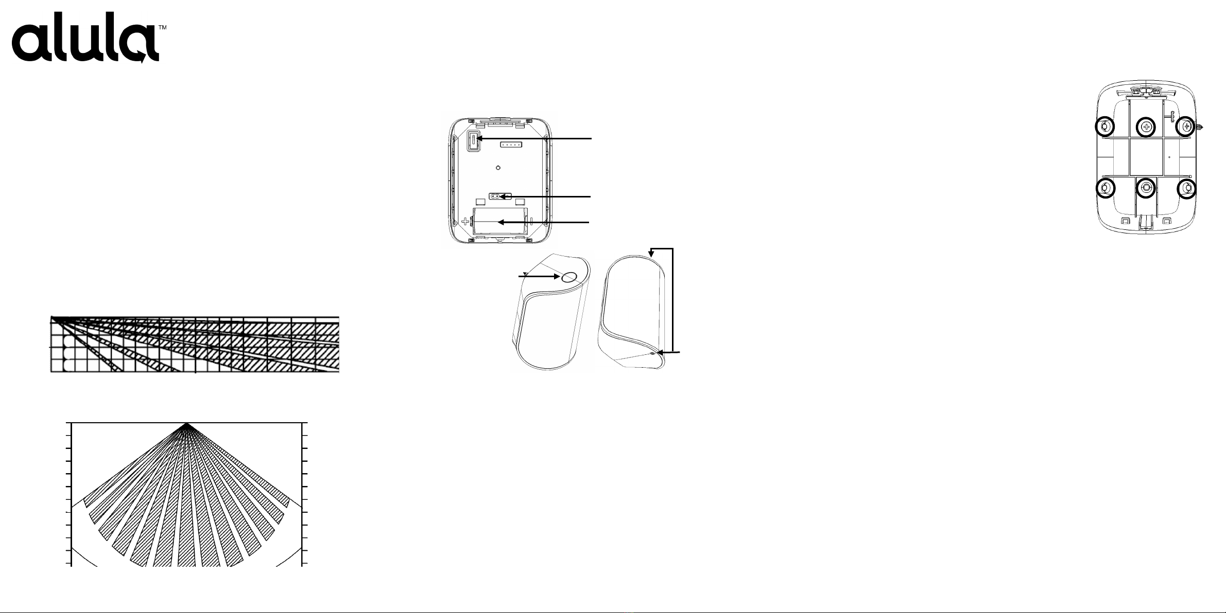
9. Maintenance - Replacing the Battery
When the battery is low, a signal will be sent to the control panel.
To insert or replace the battery:
•Remove the front cover to expose the battery.
•Remove the backplate using a bottom-to-top lifting motion.
•Remove the CR123A lithium battery. Note the correct orientation of the
battery as shown on the sensor cover plate.
Always match the plus (+) sign on the battery with the flat side of the
compartment and the minus (-) sign on the battery with the spring side.
•Replace the front cover.
WARNING: Failure to follow these warnings and instructions can lead to heat
generation, rupture, leakage, explosion, fire, or other injury, or damage. Do
not insert the battery into the compartment in the wrong direction. Always
replace the battery with the same or equivalent type (see Specifications on
page 1). Never recharge or disassemble the battery. Never place the battery in
fire or water. Always keep batteries away from small children. If batteries are
swallowed, promptly see a doctor.
• Always dispose and/or recycle used batteries in accordance with the
hazardous waste recovery and recycling regulations for your location. Your
city, state, or country may also require you to comply with additional
handling, recycling, and disposal requirements.
10. Environmental and Other Useful Information
•The RE111P PIR is an indoor use residential product only.
•While the PIR is a highly reliable intrusion detection device, it does not guarantee against
burglary. Any intrusion device is subject to a “failure to warn” for a variety of reasons.
Consider the following when installing and setting up the PIR:
•This PIR has built-in protection to keep bugs from getting into the sensor area and causing
false alarms. Note that this protection does not prevent insects from crawling across the
lens of the PIR, which could trigger the PIR.
•Infrared energy can be reflected off any glossy surfaces such as mirrors, windows, floors, or
counter tops with glossy finish, and slick-finished concrete. Some surfaces reflect less than
others (e.g. the PIR can see a change in infrared energy off of reflective surfaces even if the
heat or cold source is not within the PIR detection pattern).
•Windows reflect infrared energy. They also allow sunlight or light from other sources (e.g.,
cars) to pass through to the PIR. The PIR can detect these changes in infrared energy. For
example, if sunlight passing through a window shines onto a hardwood floor and the
change in infrared energy is quick enough, the PIR can trigger an alarm. The same applies if
the PIR area includes a window, even though the pattern of protection cannot “see”
through glass. Lights from a passing car can also pass through the window at night and
shine directly into the PIR’s lens.
•Heating and air conditioning ducts are also important because if they blow air onto an
object within the field of the PIR’s view, the temperature of that object could change
quickly enough for the PIR to “see” a change in infrared energy. PIR’s cannot see air
current, only the change in temperature of a physical object.
•The PIR senses change in temperature. However, as the ambient temperature of the
protected area approaches the temperature range of 95° to 120° F, the detection
performance of the PIR decreases.
•Ensure that the area you wish the PIR to cover is free of obstructions (for example,
curtains, screens, plants, etc.) that may block the pattern of coverage.
•Anything that can sway or move due to air current can cause a change in infrared energy
within the fields of view. Drafts from doors or windows can cause this to occur. Plants,
balloons, curtains, and hanging baskets should never be left in the PIR’s field of view.
•Do not mount the PIR on a surface that allows for any vibration. Vibrations not only cause
the PIR to move a little, but it also causes the fields of view in a room to move with respect
to the PIR. A little vibration can cause havoc with the PIR’s field of view, thus the PIR may
see a change in energy and trigger the alarm.
•An installation often requires that the PIR is aimed at the door. The PIR may detect door
movement before the door contact can initiate an entry delay, causing the alarm to trigger.
If you install the PIR facing a door, then while programming the PIR, choose an appropriate
sensor/zone type.
•The PIR ONLY detects intrusion within the pattern of coverage.
•The PIR does not provide volumetric area protection.
•The PIR creates multiple beams of protection. Intrusion can only be detected in
unobstructed areas covered by those beams.
•The PIR cannot detect motion or intrusion that occurs behind walls, ceilings, floors, closed
doors, partitions, glass doors, or windows.
•Tampering with, masking, painting, or spraying of any material on the PIR lens or any part
of the optical system can impair detection ability.
•The PIR, like other electrical devices, is subject to component failure. Even though the PIR
is designed to last as long as 10 years, the electronic components are subject to failure.
FCC Compliance Statement
This device complies with part 15 of the FCC Rules. Operation is subject to the following two
conditions: (1) This device may not cause harmful interference, and (2) this device must accept any
interference received, including interference that may cause undesired operation.
This equipment has been tested and found to comply with the limits for Class B digital devices,
pursuant to Part 15 of the FCC Rules. These limits are designed to provide reasonable protection
against harmful interference in a residential installation. This equipment generates, uses and can
radiate radio frequency energy and, if not installed and used in accordance with the instruction
manual, may cause harmful interference to radio communications. However, there is no guarantee
that interference will not occur in a particular installation. If this equipment does cause harmful
interference to radio or television reception, which can be determined by turning the equipment off
and on, the user is encouraged to try to correct the interference by one or more of the following
measures:
• Re-orient or relocate the receiving antenna
• Increase the separation between the equipment and receiver
• Connect the equipment to an outlet on a different circuit from the receiver
• Consult the dealer or an experienced radio/TV contractor for help.
Warning: Changes or modifications not expressly approved by Alula could void the user’s authority to
operate the equipment.
This device complies with Industry Canada licence-exempt RSS standard(s). Operation is subject to the
following two conditions: (1) this device may not cause interference, and (2) this device must accept any
interference, including interference that may cause undesired operation of the device.
C’et appareil est conforme la norme d'Industrie Canada exempts de licence RSS. Son fonctionnement est
soumis aux deux conditions suivantes: (1) c’et appareil ne peut pas provoquer d'interférences, et (2) c’et
appareil doit accepter toute interférence, y compris les interférences qui peuvent causer un mauvais
fonctionnement de la dispositif.
FCC ID: XQC-WST741 IC: 9863B-WST741
Trademarks
Alula is a trademark owned by Alula Holdings, LLC.
Ecolink is a trademark owned by Ecolink Intelligent Technology Inc.
All trademarks, logos and brand names are the property of their respective owners. All
company, product and service names used in this document are for identification purposes
only. Use of these names, trademarks and brands does not imply endorsement.
Alula products will function with one of either Interlogix or GE systems. However, no Alula
product is produced by, endorsed by, nor is officially associated with Interlogix or GE. Alula
recommends verifying proper enrollment and operation, per control panel installation
instructions, at installation.
RE111P Designed and manufactured by Ecolink Intelligent Technology Inc. 2022.
© 2022 Ecolink
2340 Energy Park Drive
St. Paul, MN 55108
-888-88-ALULA
PN: 47007-00xxxxx
REV & REV Date: A01 07/08/2022