manuals.online logo
Brands
  1. Home
  2. •
  3. Brands
  4. •
  5. Alula
  6. •
  7. Keypad
  8. •
  9. Alula Connect+ RE663 User manual

Alula Connect+ RE663 User manual

This manual suits for next models

1

Other Alula Keypad manuals

Alula RE152 PINPad User manual

Alula

Alula RE152 PINPad User manual

Alula RE252 PINPad User manual

Alula

Alula RE252 PINPad User manual

Popular Keypad manuals by other brands

AAA 6150RFAAA Installation and setup guide

AAA

AAA 6150RFAAA Installation and setup guide

Fermax MDS Installation and programming manual

Fermax

Fermax MDS Installation and programming manual

ACT ACT PRO 1030 manual

ACT

ACT ACT PRO 1030 manual

Cardin SSB Series manual

Cardin

Cardin SSB Series manual

Harman Kardon KP 1 Specifications

Harman Kardon

Harman Kardon KP 1 Specifications

CYP CR-KP1 Operation manual

CYP

CYP CR-KP1 Operation manual

Aeware k-35 Series Quick reference card

Aeware

Aeware k-35 Series Quick reference card

Aritech CS-175 Series user guide

Aritech

Aritech CS-175 Series user guide

Lenze AC Tech MC SERIES installation instructions

Lenze AC Tech

Lenze AC Tech MC SERIES installation instructions

Burg Wächter secuENTRY 7711 operating instructions

Burg Wächter

Burg Wächter secuENTRY 7711 operating instructions

Aeware in.k450 Tech book

Aeware

Aeware in.k450 Tech book

Lenze EPM-H410 operating instructions

Lenze

Lenze EPM-H410 operating instructions

Toshiba RKP007Z user manual

Toshiba

Toshiba RKP007Z user manual

Elmes Electronic KB1 quick start guide

Elmes Electronic

Elmes Electronic KB1 quick start guide

Clare Controls ClareOne CLR-C1-PNC Installation sheet

Clare Controls

Clare Controls ClareOne CLR-C1-PNC Installation sheet

FM Electronics 4180 quick start guide

FM Electronics

FM Electronics 4180 quick start guide

AMX MIO-PRESTIGE-S Dimensional drawing

AMX

AMX MIO-PRESTIGE-S Dimensional drawing

why pro WHY-KP user manual

why pro

why pro WHY-KP user manual

manuals.online logo
manuals.online logoBrands
  • About & Mission
  • Contact us
  • Privacy Policy
  • Terms and Conditions

Copyright 2025 Manuals.Online. All Rights Reserved.

LED Keypad is a table or wall mounted interface that chimes
and uses lit keys and an LED light bar to provide visual
arming status. The LED Keypad can be battery operated or
AC powered for exible installs.
Features
• Displays real-time status
• Wall or table mount
• AC with battery backup or battery only power
• 1 year battery life for battery only power
• User replaceable AA batteries
Use the panel installation guide to verify proper system setup.
RE663 LED Keypad
Connect+™Encrypted
I
N
S
T
A
L
L
G
U
I
D
E
I
Enroll by placing the panel and LED Keypad into wireless enrollment mode.
1. Press the enroll button on the side of the panel to put the panel into wireless enrollment mode.
2. Hold 1 and 3 simultaneously for 3 seconds on the Keypad to put the Keypad into wireless
enrollment mode. Light bar will "breathe" yellow when enrollment mode is entered.
3. The light bar will turn green if enrollment was successful or red if unsuccessful.
Operate using the LED Keypad buttons.
Light bar
• Indicates arming level with color (Disarm - Green, Stay - Cyan, Away - Red,
Night - Blue).
• Amber corners indicate trouble condition.
• AC powered operation uses full light bar. Light bar "breathes" if zones are open.
• Battery operation uses light bar corners. Light bar blinks periodically and will
double blink periodically if zones are open.
Disarm
• Indicates Disarmed
• Cancel Force Arm
• Silence Trouble beeps
(w/code if required1)
0-9 to Enter User Code
• Disarm
• Force Arm
• Arm if required1
• Silence Trouble beeps
if required1
• Press and hold 1 & 3 for
Enrollment
Stay/Away/Night
• Change & Indicates
Arming Level
• Hold Night for 3
seconds to turn
display off
Silent Arm
• Silent Arm or Disarm
Modier
• Hold and press 0-9 to
adjust volume2
Instant Arm
• No Entry Delay Modier
• Hold and press 1-9 to
adjust brightness2
1. Depends on panel settings
(Quick Arm, UL, etc.)
2. Device cannot be tampered
when changing settings
Panic Alarm Trigger
Press and hold the * and #
buttons for 3 seconds
Keypad Mounting Options
Table Top Mounting
1. Insert batteries into Keypad following polarity markings.
2. Route power cable through wire window in table stand. Connect the power supply by
inserting the barrel plug into the black port. Orient the barrel plug as shown.
3. Insert the Keypad into the table stand. Push any extra wire through the wire window before
inserting into stand. Slide the Keypad on stand until it "clicks" into place.
4. Coil up the excess power wire into the stand. Insert wire into wire holder and close stand
cover to contain excess wires.
5. Plug in power supply.
Wire window
Wire holder
Barrel plug
Wall Mounting
1. Insert batteries into Keypad following polarity markings.
2. Fasten to wall by screwing the screws through the two holes into the wall. Screws should be
fastened to a stud, a single gang box, or with wall anchors into drywall. Ensure power supply
wires are routed through wire window and seated in wire channel if wire does not run behind
drywall.
3. Route power cable using one of two methods.
A. Wires to Terminal Block: Connect one end of the wires to the terminal block. Splice the
other end of the wires to the provided power supply. Polarity does not matter. Wire
lengths must not exceed lengths listed below.
B. Barrel Plug: Connect the power supply by inserting the barrel plug into the black port.
Orient the connector as shown.
4. Insert the Keypad into the wall mount. Push any extra wire through wire window before
inserting onto wall mount. Slide the Keypad until it "clicks" into place.
5. Plug in power supply.
WIRE
GAUGE
MAXIMUM LENGTH BETWEEN
POWER SUPPLY AND KEYPAD
#24 Up to 50 feet
#22 Up to 100 feet
#20 Up to 150 feet
#18 Up to 250 feet
#16 Up to 400 feet
Wire window
Wire channel
Terminal block
Screw hole
Screw hole
Barrel plug
Pro Tips
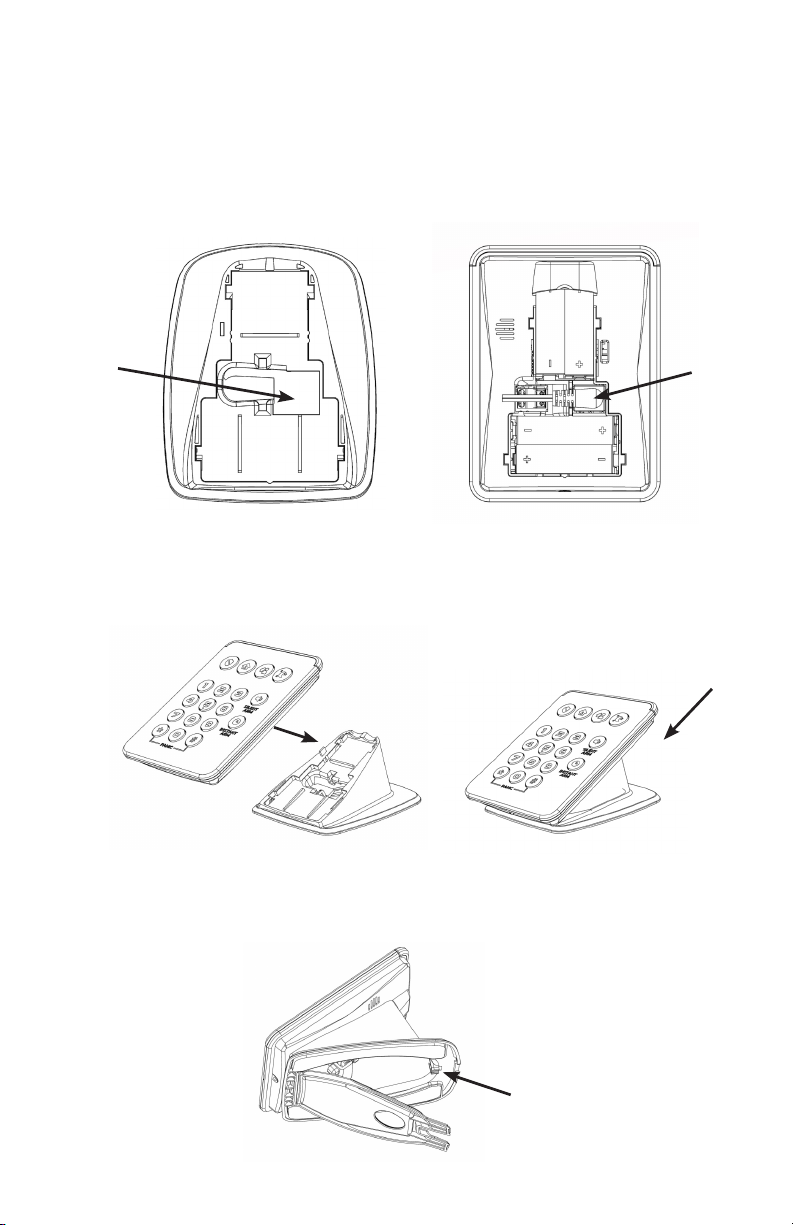
Wire can be hidden by running the wires through a hole behind the wall mounting plate and along
the back side of the drywall to a location with an outlet.
Switching to battery only power mode can be done by restarting the keypad with the battery
power. First, remove wall power supply and batteries. Wait 10 seconds. Then, power the keypad
back up with only batteries. In battery only power mode, AC failure will not be indicated.
Unenrollment can be done by following the same steps as enrollment.
Force unenroll can be done when no panel is present. Hold the 1 and 3 keys simultaneously to
enter unenrollment mode. After the keypad fails to unenroll, hold the 1 and 3 keys simultaneously
again to force unenroll.
AC loss will cause an AC fail trouble condition after 1 minute and will switch to battery operation
blinking display after 10 minutes of continued AC loss.
Adjust blink rate by holding the Instant Arm button and pressing the * or # key. This can only be
done when the device is operating in battery only mode and is not tampered. Blink interval
options are Off, 10 seconds (default), 5 seconds, and 2.5 seconds. A portion of the light bar will
illuminate to indicate how much feedback will be given.
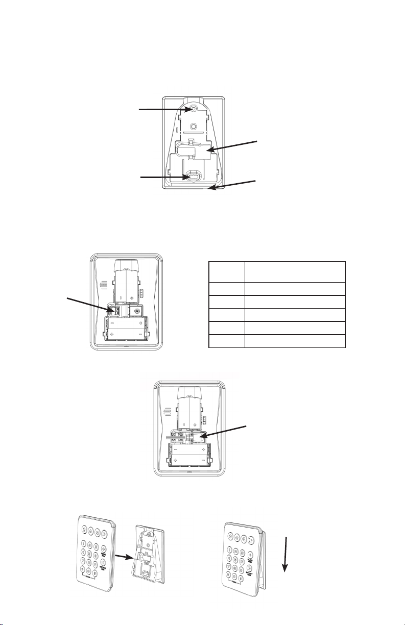
Specications
Physical
Wall Dimensions
Table Top Footprint
Weight
Mounting Fasteners
Pilot Hole for Screw into Wood
Pilot Hole for Wall Anchor
3.81 x 5.10 x 1.55 inches (9.68 x 12.94 x 3.94 cm)
3.81 x 5.47 x 3.17 inches (9.68 x 13.89 x 8.05 cm)
1.49 lb (675 g)
#6 screws & 2 wall anchors (included)
Ø 1/8 in (3 mm)
Ø 3/16 in (4.7 mm)
Environmental
Operating Temperature
Maximum Humidity
32 to 120°F (0 to 49°C)
85% relative humidity non-condensing
Device Specications
Frequency
Power Supply
Input
Output
Part Number
Replacement Battery
Nominal Battery Life
Current Draw
Transmitted Indications
2.4 GHz
100-240VAC, 50/60Hz, 0.5A
12VDC, 1A
RE012-6
4 AA batteries
1 year (Battery only operation under normal use)
350mA (Maximum)
Low Battery, Supervision, Tamper, AC Fail
Certication
RE663 FCC, IC
Specications subject to change without notice.
IC NOTICE
This device complies with Industry Canada license-exempt RSS
standard(s). Operation is subject to the following two conditions:
(1) This device may not cause interference, and
(2) This device must accept any interference, including interference
that may cause undesired operation of the device.
Le présent appareil est conforme aux cnr d’Industrie Canada
applicables aux appareils radio exempts de licence. L’exploitation
est autorisée aux deux conditions suivantes:
(1) L’appareil ne doit pas produire de brouillage, et
(2) L’utilisateur de l’appareil doit accepter tout brouillage
radioélectrique subi, même si le brouillage est susceptible d’en
compromettre le fonctionnement.
IC: 8310A-RE663
FCC NOTICE
This device complies with Part 15 of the FCC rules. Operation is
subject to the following two conditions:
(1) This device may not cause harmful interference.
(2) This device must accept any interference that may be received,
including interference that may cause undesired operation.
Changes or modications not expressly approved by Alula could void
the user’s authority to operate this equipment.
FCC ID: U5X-RE663
TRADEMARKS
Alula and Connect+ are trademarks owned by Alula Holdings, LLC.
47-00012 • REV A • 2021-04-13
Tech Support Line • (888) 88-ALULA • (888) 882-5852
alula.com
01