5. LAGERUNG, TRANSPORT
UND ENTSORGUNG
Die Lagerung des Produkts sollte verpackt in geschlossenen, trocke-
nen Räumen bei einer Lufttemperatur von 0…+ 25°C und einer
relativen Luftfeuchtigkeit von 80% in Abwesenheit von sauren,
alkalischen und anderen aggressiven Verunreinigungen erfolgen.
Gegen Niederschlag oder direktes Sonnenlicht schützen. Das Pro-
dukt ist 2 Jahre ab Herstellungsdatum lagerfähig. Das Produkt kann
mit allen Arten von gedeckten Bodentransportmitteln in Innenräu-
men, die Stöße und Bewegungen im Fahrzeuginneren ausschließen,
befördert werden.
Die Entsorgung erfolgt gemäß den im Land des Be-
treibers geltenden gesetzlichen und behördlichen
Recycling- und Entsorgungsvorschriften. Das Produkt
enthält keine Edelmetalle und Stoe, die für das Leben,
die menschliche Gesundheit und die Umwelt gefähr-
lich sind. Die Lebensdauer – 5 Jahre.
6. GEWÄHRLEISTUNG
Die Funktionsfähigkeit des Produktes wird bei Einhaltung der Vor-
schriften für Lagerung, Transport und Betrieb garantiert. Die Gewähr-
leistungsfrist für den Betrieb beträgt 3 Jahre. Während der Garantiezeit
werden die Störungen, die durch den Fehler des Herstellers verursacht
wurden, vom Kundendienst der Serviceabteilung, die Garantieleistun-
gen erbringt, behoben.
Hinweis: die im Rahmen der Garantie ausgetauschtenTeile werden Eigen-
tum des Kundendienstes, der die Produktreparatur durchgeführt hat.
Die Produktgarantie gilt nicht in folgenden Fällen:
• Verstoß gegen die Vorschriften für Lagerung und Betrieb des
Produkts;
• Änderung des Produkts durch die nicht autorisierten Personen,
Schäden durch den Betreiber oder Dritte;
• Schäden am Produkt durch Eindringen von Wasser;
• höhere Gewalt (Brände, Blitzeinschläge, Überschwemmungen,
Erdbeben und andere Naturkatastrophen);
• die ausgefüllte Anleitung wurde nicht vorgelegt.
Kundendienst nden Sie unter:
http://www.alutech-group.com/feedback/service/
7. ZERTIFIKATE
Kopien der Konformitätserklärungen sind unter http://www.
alutech-group.com/product/other/auto/DOCUMENTS/ erhältlich
Hergestellt in China
Hersteller: Hangzhou Hiland Technology Co., Ltd’
4th Building, 2 Xiyuanwu Road, Westlake Technology Garden,
Hangzhou, China +86 571 81958376
Importeur in der EU/Bevollmächtigter Vertreter des Herstel-
lers: ALUTECH Systems s.r.o., 348 02, Tschechische Republik, Bor
u Tachova, CTPark Bor, Nova Hospoda 19, D5-EXIT 128
Telefon/Fax: + 420 374 6340 01
DEUTSCH
1. BESCHREIBUNG
Die Lichtschranken sind dazu vorgesehen, das Vorhandensein von
Fremdkörpern auf der optischen Achse zwischen dem Sender (TX)
und dem Empfänger (RX) von Lichtschranken zu signalisieren.
2. LIEFERUMFANG
Sender (TX).................................................... 1 Stk.
Empfänger (RX)................................................ 1 Stk.
Anleitung ...................................................... 1 Stk.
Dübel mit Schraube............................................ 8 Stk.
3. TECHNISCHE DATEN
Versorgungspannung.............................. 12…24 V AC/DC
Sender-Verbrauch (TX)...................................... ≤15 mА
Empfänger-Verbrauch (RX)................................. ≤30 mА
Reichweite ...................................nicht weniger als 12 m
Positionierungsgenauigkeit ...................................... ±5°
Lastleistung von Relaisausgangskontakten ....... 1 A/max. 30 V DC
Art der Ausgangskontakte ...............................NC und NO
Wellenlänge der Infrarotstrahlung ...........................940 nm
Schutzart der Abdeckung....................................... IP 54
Betriebstemperaturbereich ........................... −20…+60 ºС
Abmessungen .......................................90×55×27 mm
Querschnitt der Anschlußleitungen ....... max. 1 mm (AWG16-26)
Anzeige ......................................... LED am Empfänger
(leuchtet beim Auslösen der Lichtschranken)
YDas Unternehmen behält sich das Recht vor, ohne vorherige
Benachrichtigung Änderungen in dieser Anleitung vorzuneh-
men und die technischen Daten des Produktes zu ändern. Der
Inhalt der vorliegenden Anleitung gilt nicht als Grundlage für
Rechtsansprüche.
4. MONTAGE UND ANSCHLUSS
YDie Montage und der Anschluss des Produktes sind von qua-
liziertem Personal in Übereinstimmung mit den geltenden
Vorschriften und unter Beachtung der Sicherheitsmaßnah-
men auszuführen.
YBevor irgendwelche Anschlüsse vorgenommen werden, stel-
len Sie sicher, dass die Automatik, an die die Lichtschranken
angeschlossen werden, von der Hauptstromversorgung und
ggf. von der Batterie abgetrennt sind.
Vor der Motage der Lichtschranken müssen die Montagestellen für
Sender und Empfänger so gewählt werden, dass sie mindestens
20 cm hoch sind und sich in einer geraden Linie gegenüberlie-
gen. Der Abstand zwischen Sender und Empfänger muss mehr als
50 cm betragen. Stellen Sie sicher, dass die gewählten Montage-
stellen vor Stößen geschützt sind und dass die Montageächen
fest genug sind. Verlegen Sie die Kabel zu den Montagestellen von
Sender und Empfänger im Voraus.
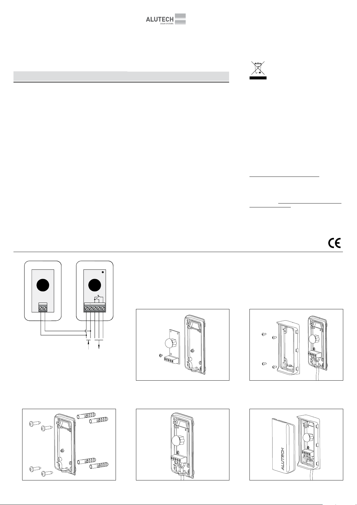
Bei der Montage zunächst den Sender befestigen und die elektri-
schen Anschlüsse vornehmen (siehe Schema), dann den Empfän-
ger ausrichten (Justage vornehmen) und anschließen. Die Licht-
schranken sind korrekt angeschlossen und ausgerichtet, wenn die
LED des Empfängers nicht leuchtet und bei Durchqueren des opti-
schen Strahls die LED aueuchtet und es ist zu hören, wie das Relais
schaltet. Überprüfen Sie die Funktion der Lichtschranken mehrmals.
YWegen möglicher Reexionen der Infrarotstrahlen von Fuß-
böden, Wänden, Gegenständen usw. sollten die Lichtschran-
ken nur mit eingebauten Abdeckungen geprüft und betrie-
ben werden, die als Filter das sichtbare Licht absperren und
Linsen enthalten, die die Strahlen bündeln. Direkte Sonnen-
einstrahlung auf den Empfänger der Lichtschranken sollte
vermieden werden.
Montage- und Anschlusspläne sind in Abb. 1-6 dargestellt.
Bedienungsanleitung
LICHTSCHRANKEN
LML
5. STORAGE, TRANSPORTATION
AND DISPOSAL
Keep the packed product in dry premises at temperatures between
of 0…+25 °С and relative air humidity no more than 80%. The air
inside the premises must not contain acidic, alkaline and other ag-
gressive substances. Do not expose the product to the precipitation
or direct sunlight. Storage period—3 years from the date of manu-
facture. Transportation may be carried out by means of any roofed
land vehicle tted with the means to prevent crushing of packages
and load retention equipment.
Disposal is to be performed in accordance with the
current waste processing and disposal regulations ap-
plicable in the country of the Customer. The product
does not contain precious metals and substances that
pose a threat to life, human health or the environment.
Operation life—5 years.
6. WARRANTY
The warranty on the operation capacity of the product is provided if
the storage, transportation and maintenance operations are carried
out according to the set regulations. The warranty period is three
years. Under the warranty, the service department only eliminates
malfunctions caused by the fault of the Manufacturer.
Note: the parts replaced under the warranty are considered the pro-
perty of the service department that carried out the product repair.
The warranty does not apply in the following cases:
• violation of use and storage regulations;
• alterations performed by unauthorised persons, damage of the
products caused by the consumer or third parties;
• damage caused by water ingression within the device;
• force majeure (fires, lightning strikes, floods, earthquakes and
other natural disasters);
• failure to provide a completed operation manual.
For questions about the service please contact the organization
that carried out the installation of the equipment.
7. STATEMENT OF COMPLIANCE
Copies of declarations of compliance can be found at:
http://www.alutech-group.com/en/products/other/automatics/
documents
Made in China
Manufacturer: ‘Hangzhou Hiland Technology Co., Ltd’
4th Building, 2 Xiyuanwu Road, Westlake Technology Garden,
Hangzhou, China +86 571 81958376
Importer to the EU/Authorised representative of the Manu-
facturer: ALUTECH Systems s.r.o., 348 02, Czech Republic, Bor
u Tachova, CTPark Bor, Nova Hospoda 19, D5-EXIT 128
Phone/fax: + 420 374 6340 01
ENGLISH
1. DESCRIPTION
The photocells are designated to warn of any foreign objects on
the optical axis between the transmitter (TX) and the receiver (RX)
of the photocells.
2. DELIVERY SCOPE
Transmitter (TX)................................................. 1 pc.
Receiver (RX).................................................... 1 pc.
Manual .......................................................... 1 pc.
Dowel with screw ............................................... 8 ps.
3. TECHNICAL SPECIFICATIONS
Supply voltage ..................................... 12…24 V AC/DC
Transmitter (TX) consumption .............................. ≤15 mА
Receiver (RX) consumption ................................. ≤30 mА
Range ............................................ not less than 12 m
Positioning accuracy ............................................. ±5°
Output relay contacts load......................... 1 А/max 30 V DC
Output contacts type .................................... NC and NO
Infrared wave length ......................................... 940 nm
Housing protection class........................................ IP 54
Working temperature range .......................... −20…+60 ºС
Measurements .......................................90×55×27 mm
Connection cable cross-section............ max 1 mm (AWG16-26)
Display ............................................... LED in receiver
(is lit when active)
YThe company reserves the right to make changes to this
manual and technical specications of the product without
prior notice.The content of this manual cannot form the basis
for legal claims.
4. INSTALLATION AND CONNECTION
YOnly qualied specialists can install and connect the product
in compliance with the regulatory documentation in force and
following the applicable safety procedures.
YBefore making any connections, check that the automation
to which photocells are connected is disconnected from the
mains and from the batteries, in case of accidental activation.
Before mounting the photocells select the location for the trans-
mitter and receiver and place them on one level at height of not
more than 20 cm and endure they are facing one another in a di-
rect line. The distance between transmitter and receiver should
not exceed 50 cm. Check that the selected mounting places are
protected from impacts and the mounting surfaces are strong
enough. Lay the cables to the transmitter and receiver mounting
places beforehand.
When mounting, fasten the transmitter rst and connect electric
cables (see diagram), then align (center) and connection the re-
ceiver. The photocells are connected and aligned correctly, if the
receiver LED is not illuminated, and when crossing the optical ray
the LED illuminates and relay switching is heard. Check the LED
operation several times.
YDue to possible reections of infrared rays from the oor,
walls, objects etc. the photocells should be checked and used
only with their lids installed b, which serve as lters for cut-
ting the visible light and containing the lenses which focus
the rays. Protect the photocells receiver from direct sun light.
The installation and connection drawings are shown on g. 1–6.
Operating
manual
PHOTOCELLS
LML