Alutech Sun Shield EM3430L User manual

1
Instruction manual for Retractable Awning
(EM3430L-5.95x3.5m/3.95x2.5m)
Contents
Packinglist..................................................................................... 2
Description............................................................................................. 3
Safetyinstructions............................................................................ 3-4
Preparation................................................................................... 4
Mounting.................................................................................................. 5-8
Operation................................................................................................. 8
Adjusting pitch angle........................................................................
Extend and retract awning..................................................... 8
9-10
EngineSetting............................................................................................ 11
General notes of theawningfabric………………………… 12
Electricalconnectionguide....................................................................................13
Attention!
Read the operator’s instruction before the mounting and use of the product. Keep
the instruction in a safe place for future reference.
Dear Customer,
Congratulations for buying an awning out from the electical awning. For your own and the safety of
other people please pay attention to the following leads and follow safety instructions.
Before you start mounting and using the awning, please get familiar with this product. Make sure
all parts listed up in below packing lists are delivered and intact. If you find that there are parts
missing or damaged please do not install the awning but contact your dealer.
!

Packi
n
No matt
e
packag
e
Br
n
g list
e
r which ty
p
e
:
acket with
h
S
c
Anc
h
p
e of the aw
n
h
exagon he
a
c
rew
h
or with loc
k
C
Ins
t
R
M
n
ing series
y
Part
Awning
a
d bolt and l
Plastic Bo
l
k
nut, washe
r
C
rank handl
e
t
ruction ma
n
R
emote cont
r
M
otor adjust
o
Hook
2
y
ou bought,
ocknut for
w
l
t G
a
r
and lockin
g
e
n
ual
r
ol
o
r
the followi
n
w
all and ceil
i
a
sket
g
ring
n
g parts sho
u
i
ng
≤
u
ld be in th
e
Quant
1
≤
5m
3
6
6
1
1
1
1
1
e
i
ty
≤6m
4
8
8

Descri
1
Val
a
2
Fa
b
3
Bra
4
Rai
5
Sid
e
Impor
t
W
A
Symbol
Th
Safetyi
n
!
!
!
ption
a
nce
b
ric
cke
t
n cover
e
cover
t
ant safet
y
A
RNING –
I
explanati
o
This war
n
injuries o
r
is sign iden
t
n
structions
To install
yourselfif
yo
u
i
n
yo
u
yo
u
yo
u
A minim
u
product i
s
could ca
u
6
7
8
9
y
instructi
I
T IS IMPO
R
INSTR
U
o
n
n
ing triangle
r
which are
i
t
ifies import
a
this awning
u
are unsur
e
n
stallation.
u
do not un
d
u
do not ha
v
u
do not ha
v
u
m of three
s
big and h
e
u
se serious i
6
Gear
b
7
A
ngle
8
Torsio
9
Roller
10
A
rm
ons!
R
TANT FO
R
U
CTIONS.
S
calls attent
i
i
mportant f
o
a
nt notes.
technical k
n
e
if the aw
n
d
erstand th
v
e necess
a
v
e necess
a
healthy ad
u
e
avy. Do n
o
njuries and
3
b
ox
adjustment
n bar
R
SAFETY
O
S
AVE THE
S
i
on to haza
r
o
r the functi
o
n
owledge i
s
n
ing can be
e instructio
a
ry tools av
a
a
ry technica
u
lts are req
u
o
t try to ins
t
damages!
C
O
F PERSO
N
S
E INSTRU
C
ds that that
o
ning of the
necessary.
mounted o
n manual o
a
ilable.
l knowledg
e
u
ired to mo
v
t
all the aw
n
C
ontact an
a
11
F
12
C
N
S TO FOL
C
TIONS
can lead to
awning.
Do not mo
u
n the place
r parts of it
.
e
.
v
e and inst
a
n
ing alone.
I
a
uthorized a
F
ront bar
C
rank
LOW THE
S
death or to
u
nt this awn
you chose
.
a
ll the awni
n
I
f the awni
n
ssembler f
o
S
E
severe
ing
for
n
g as the
n
g falls, it
o
r help.

4
Do not install the awning when you find damage parts are that parts are missing.
Do not allow children to play in the working area during assembly
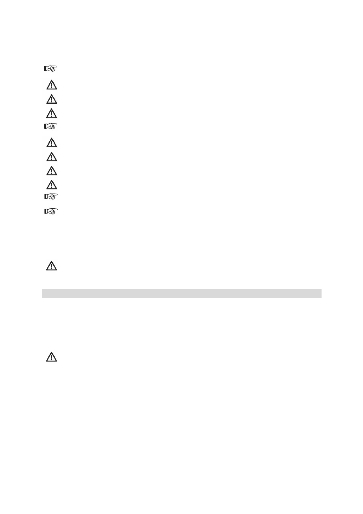
This product is only suitable for installation in the cement wall or ceiling.
Nobody is allowed to change the products’ design and structure without the permission
of manufacture or authorized deputy.
Please make sure that your hands are clean at the time of the assembly; otherwise you
may soil the awning fabric and frame.
The operation in frosty conditions may damage the awning.
The operation in snowy conditions may damage the awning.
In case of rain Retract the awning if pitch angle is less than 14°.
Nobody is allowed to climb onto the awning; hanging anything on the awning is
Sheeting was used to protect the paint. This must be removed afterwards.
When extended, various forces, including wind and rain, will affect an awning. These
sometimes substantial forces must be absorbed by the awning and transferred to the
assembled structure via its mounting brackets. Under extreme loads, excessive
attractive force can be exerted on the anchor bolts. Therefore, before starting assembly,
check the load-bearing capacity of the mounting base and if necessary take
corresponding measures to ensure stable installation of the brackets. If the mounting
base is unstable, you may wish to consult a specialist in yourvicinity.
The awnings are intended as a protection against the sun only. It is not to be used
during periods of strong wind, rain, hail, or snow. In case of such conditions, retract the
awning immediately.
Preparation
Carefully remove the awning from the box and remove the styrofoam protectors from the awning.
Remove the plastic bags and plastic guards from the awning and carefully place the awning aside
to avoid having it damaged by scratches or otherwise damaged or soiled during assembly. Check
the number of parts in the packaging whether the packing list requirements, the quality of parts
availability issues, if questions, please contact the supplier.
Be aware the sudden extension may occur during unpacking.
Tools needed for assembly:
Drill
Masonry drill bit, 14 mmLevelindicator
Wrench13mm、17mmand19mm
Stepladder
Tape measure
Chalk or marker pen
Wooden hammer

5
2
X+10cm
Mounting
Mounting on concrete wall or ceiling
The awnings must be installed at least at the height of 2.5 m on a reinforced concrete wall
or ceiling. Please ask professionals for help if you are notsure.
Make sure the wall/ceiling is plane, so that bracket seats solidly.
WARNING Three healthy adults are needed to move and install the awning.
For safe and smooth installation think about how you will be securing the awning to
the wall ahead of time.
Step 1: Chose the installation area
Ensure that you also take this drop height into account in your decision on where to install the awning.
The drop angle can still be changed after assembly. The ideal drop angle, however, has already
been set at the factory and may only be changedminimally.
The approximate total drop area of the awning varies depending on the type. We recommend that
the awning front bar has a height of at least 2.5 m when it is fullyextended.
In the event you would like to mount it above a balcony door, you should leave a space of at least 20
cm above the door frame if there is enough space available above the door frame.
Drawing 1:
Ensure that you also take this drop height into
account in your decision on where to install the
awning. The awning front bar should have a
height between 2.5 and 4 m.
Step 2: Mark drilling holes
After choosing mounting position you can mark where you need to drill holes for the brackets. Draw
ahorizontallineattheheightoftherequiredplace.Usealongtapermeasure,alevelandchalk.
We already marked where and with what width brackets need to be mounted. Measure the width
between the brackets and copy it to the line on your wall/ceiling.
Mark the corresponding places on the wall by running a marker pen through the holes at the bottom
of the brackets.
Make sure the two outer brackets are located outside of the arm stands and one is located in the
middle of the awning, see Drawing 2.
Drawing 2:
Mark where you need to drill holes for
brackets with a chalk line to ensure awning
is straight.

6
Step 3: Drill holes
Use 14-mm masonry drill to drill the holes for the brackets at the appropriate marks on the wall. The
holes should be 9 cm deep in the wall and must be drilled through solid masonry or concrete. Do not
bore through mortar because this does not offer the strong enough support that is required by the
installation of awning.
Drawing 3:
Use 14-mm masonry drill to drill 9 cm deep
holes.
Step 4: Insert anchors into wall
After drilling the holes you can insert the anchors into the wall. Remove lock nut, washer and locking
ring before you insert the anchor. Store these parts so that you can reach them easily in the next
step.
It may be necessary to drive the anchor bolts in with a wooden hammer because they do not
go in easily. Do not use a metal hammer for this purpose because this could damage the
threads on the top of thebolts.
If the bolts need to be driven into the wall with a hammer, we recommend initially placing the
nut on the screw loosely (only placing it loosely on the bolt) because this avoids damage to
the boltthreads.
Drawing 4:
Insert the anchor into the drilled hole as
shown in picture on the right

Step 5: Fi
x
Place the
b
the bracke
t
Drawing 5:
Bracket h
a
fixed on a
you need t
o
drawing.
Fir
m
r
A
movingi
n
f
D
a
Step 6: I
n
After all
t
are requi
r
firmly re
s
assembl
y
Insert th
e
screw an
d
x
ing the br
a
b
racket on
t
t
with lock n
a
s been pre
p
wall. Chos
e
o
fix them
a
m
ly tighten t
h
r
ather than
a
A
ssoonasth
e
n
anyform,yo
f
irmly to the
D
o not try t
o
a
bsolutely fi
r
n
stall awni
n
t
hree brack
e
r
ed to insta
l
s
ting on th
e
y
work.
e
awning in
d
fix it with l
o
a
ckets
t
he screw p
uts. Tighte
n
p
ared to be
e
the whole
a
ccording to
h
e bolts wit
h
a
n open en
d
e
yarefullyin
s
umustfurth
e
wall, so tha
t
o
secure the
r
m.
n
g
e
ts have be
l
l the awnin
g
e
ground s
o
to bracket
s
o
ck nut. Att
a
rotruding fr
o
n
themwell.
h
a 17mm
w
d
because t
h
s
erted,thebr
e
rtightenit.E
n
t
they can i
n
wall bracke
en mounte
d
g
in order t
o
o
that you
c
s
as show
n
a
chment br
a
7
o
m the wall
w
rench: it is
b
h
is will avoi
d
acketsmust
s
n
surethatth
e
n
no case te
ts to loose
w
d
properly y
o
obtain th
e
c
annot fall.
n
in drawin
g
a
ckets for w
a
. Then add
b
est to use
a
d
damage to
s
itfirmlyinth
e
e
wallbracke
t
ar out when
w
all stones
o
o
u can fix t
e
required h
e
Only use l
a
g
below. T
h
a
ll and ceili
n
locking rin
g
a
wrench wi
t
the nut if it
e
wall.Ifthey
a
t
sarescrew
e
the awning
o
r any surfa
he awning.
e
ight. Ensu
r
a
dders that
h
en immedi
a
n
ginstallatio
n
g
and wash
e
t
h a closed
e
shouldslip.
a
restill
e
d
is installed
.
ces that ar
e
At least th
r
r
e that the l
a
are suitabl
a
tely insert
n
:
e
r and fix
e
nd
.
e
not
r
ee ladders
a
dders are
e for such
the safety

8
Drawing 6:
Insert awning to bracket
as shown. Fix the awning
with delivered safety
screw and lock nut and
tighten it properly.
In case the square tube cannot be inserted into the wall brackets, you should slightly loosen
the wall bracket screws and then try it once again. This time, move the awning slightly
forward and backwards until the bearing tube slips into the brackets. Then immediately
insert the safety screw and fix it with lock not. Use a 19 mm wrench to tightenit.
Attention Also tighten the safety screws of wall brackets again and ensure that they have
been adequately secured.
After the awning has been mounted properly and has been adequately secured please take
away the protective band that you can find on the arm of the awning. Otherwise it cannot be
opened. Store the protective band; you can use it in future when storing theawning.
Attention: Misplacing and misapplying the awning can cause seriously danger. Only mount
the awning yourself when you understand the mounting instructions completely and when
you are sure that the wall or ceiling you want to mount the awning on is suitable. For your
own and the safety of other people please contact an authorized assemblerfor help.
Operation
Adjusting the pitch angle
The awning is already delivered with an optimally adjusted pitch angle. However, users can adjust
the screen angle within a range of 5 - 45 degrees as desired.
Extend the awning no more than 1/4 of its full projection before adjusting.
Once you have achieved the highest possible range of pitch, the loop cannot be turned any
farther. Do not force it Failure to follow these instructions can damage the flex pitch
shoulder and void thewarranty.

9
Drawing 7:
The pitch angle can be adjusted on all arms
in the adjusting area (7.1).
Take off the plastic caps, loosen the locking
bolts 9 with a 14mm wrench.
Turn the adjusting screw clockwise to
decrease the pitch angle; turn counter-
clockwise to increase the pitch angle. When
achieved to the desired pitch angle, tighten
the safety nuts and put the plastic caps
back on it (7.2).
Follow the same procedure until all arms have been adjusted to the desired level.
The front bar must always be level. To ensure that both sides are completely level, a built-
in level is located on the front bar: the air bubble must be exactly in the middle of the level.
Place the plastic caps on the screws to protect them against weather basedcorrosion.
Always remove the crank handle and keep it in a safe and dry place.
Extend and retract the awning
The awning can be extended and retracted by a crank handle included in delivery or remote control.
Drawing 8.1:
Insert the handle in the loop that is
fixed at the awning. Open the awning
by turning the crank handle clockwise.
By turning it counter-clockwise you
can retract theawning.
8.1

The aw
n
Drawin
g
P
r
the aw
n
the aw
n
Pres
s
the aw
n
awning
Pres
s
the ext
e
T
t
T
p
i
N
B
c
D
r
W
t
T
p
n
ing can be
g
8..2:
r
ess the ext
e
n
ing extensi
o
n
ing will bee
x
s
the retra
c
n
ing. The
r
will be retr
a
s
the stop
b
e
nsion/ retr
a
T
he awning
'
t
o the fabric
T
he awning
s
p
eriods of
s
mmediatel
y
N
ever allow
B
e sure the
c
ounte
r
-clo
c
D
o not put
a
r
etracting.
H
W
hen the fr
o
t
o make the
m
T
ake out th
e
p
lace that is
extended a
e
nsion butt
o
o
n. The role
x
tended.
c
t button
r
ole moves
a
cted.
b
utton "S
T
a
ction of the
a
'
s crank ge
a
, therefore,
t
s
are inten
d
s
trong wind,
y
.
children to
fabric is te
n
c
kwise until
t
a
ny objects
o
H
azard of cr
u
o
nt bar tou
c
m
closer, ot
e
crank han
d
not reacha
b
nd retracte
d
o
n "EXT"
f
moves up
a
"RET" to c
l
down and
T
OP" to st
o
a
wning.
Remot
e
a
r has no st
o
t
he awning
f
d
ed as a pr
o
rain, hail,
play with th
e
n
sioned. If t
h
t
he fabric is
o
r parts of y
o
u
sh
c
hes the roll
e
herwise the
d
le from loo
p
b
le for child
r
10
d
by a remo
t
f
or
a
nd
l
ose
the
o
p
e
control
o
p to limit r
e
f
abric must
a
o
tection ag
a
or snow. In
e
awning.
h
e fabric is
n
tensioned.
o
ur body e.
e
r as show
n
product mi
g
p
after adju
s
r
en to avoid
t
e control in
c
e
volutions o
f
a
lways be
p
a
inst the su
n
case of s
u
n
ot tensione
d
g. hands, i
n
in followin
g
g
ht be dam
a
s
ting the aw
that they pl
8.2
c
luded in d
e
f
the roller t
p
roperly roll
e
n
only. It is
u
ch conditio
d
during ext
n
the awnin
g
g
figure duri
n
a
ged.
ning as you
ay with the
e
livery.
ube. To av
o
e
d up.
not to be
u
ns, retract
t
ension, ple
a
g
while exte
n
n
g retractio
n
wish and p
u
awning.
o
id damage
u
sed during
t
he awning
a
se turn
n
ding and
n
, don’t try
u
t it on a

11
Engine setting(off/on setting)
Factory default setting is best for the engine .
Larger settings before its use should therefore not be necessary. In the following cases, however,
the engine should be a bit readjusted if:
1 Theawningdoesn`t close completely.
2 The cover isloose.
3 The engine is not running yet, although the awning is fully closed.
Change the maximum distance of the awning, by using the enclosed tool. Use the motor
adjustment tool to adjust the motor,.
Use the front motor adjustment screw to adjust the maximum distance (see Figure M).
Turn the adjustment screw with the tool in counterclockwise direction "+" to increase the maximum
distance.
Turn the adjustment screw with the tool 20 in a clockwise direction "-" to reduce the
maximum distance.
Use the rear adjustment screw to adjust the minimum distance(see FigureN).
Turn the adjustment screw withthetool in counter-clockwise direction "+" in order to increase
the minimum distance.
Turn the adjustment screw withthetool in clockwise direction "-" to reduce the minimum
distance.
NOTE: If the motor does not start on after repeated on setting, please wait 30 minutes and start it
again afterwards.
NOTE: Over loading the motor is not good. Doing so may shorten its lifespan.
Handling of the remote control
Note: There are legal limitations for the transmission range of radio waves. The maximum range is
also limited by physical obstacles.
Before installing, check whether the remote device and the awning are working correctly ,Before you
install the hooks.
To allow reaching almost every vertical area below.
Make sure that the mount is in a place to install the corresponding prescribed protection (IP 20) of
the remote .
Do not mount on metal or magnetic objects to avoidinterference.
Battery/Use
NOTE: When you insert the battery make sure that the contacts are not bent.
Open the battery compartment with the spanner in the battery compartment lid in the direction of
the battery compartment and press the battery compartment cover , then the battery
compartment slides.
Put the battery in accordance with polarity and labeling in thebattery
Close the battery compartment , by clicking the two extensions of the battery compartment lid in
the two cutouts on the battery compartment.
Then press the skewer of the battery compartment lid into the hole at the battery compartment.
The battery compartment cover snaps in with a click.
If the remote control could not function, then check whether the batteries are inserted correctly
and put them again if necessary.

General notes of the awningfabric
Awning fabrics are high performance products. Nevertheless, even given today's state of the art and
the requirements imposed by environmental protection, there are limits to perfection. Certain
appearances in the fabric that are sometimes objected to are still possible despite sophisticated
production and processing technology.
Basically, these effects occur to different degrees in almost all awning fabrics. They do not decrease
the quality of the fabrics in any way, however.
To avoid irritation, we would like to expressly draw your attention to the following characteristics in
terms of consumer education:
Creases are created during fabrication and when folding the awning fabric. In the course of
this process, especially in lighter colors, surface effects can be created in the crease
(pigment displacements), which appear darker with backlight (like stripe of dirt). They do not
decrease the value or the performance of theawning.
Chalk effects are light stripes that are created when processing refined goods and cannot
be totally avoided even with the greatest of care. Thus, they also do not constitute a reason
for complaint.,
Rain impermeability: Acrylic and polyester sun protection awning materials are impregnated
with water-repellents and at a minimum tilt of 14 degrees will withstand a light, short rain. In
stronger or longer rain, awnings must be retracted to avoid damage. Awnings that are rolled
up wet should be extended again as soon as possible fordrying.
Ripples in the seam, stitch and panel areas are caused by multiple layers of the fabric and
various winding strengths in the roller tube. Fabric tension thus caused can cause ripples
(e.g. waffle or herringbonepatterns).
The fabric's yarn need not be the same9 color as the part of the fabric that contains the seam.

Table of contents
Other Alutech Accessories manuals
Popular Accessories manuals by other brands

Oakley
Oakley AIRWAVE 1.5 owner's manual

Woodstock
Woodstock G2372 instruction manual

Siemens
Siemens Symaro QSM2100 manual

IFM Electronic
IFM Electronic efector160 LR7000 operating instructions

Seeed Technology
Seeed Technology SenseCAP LoRaWAN 868 user manual

AS Technology
AS Technology Titan Power 14-50 user guide