Always “On” UPS M4101 User manual

**WARNING: ONLY AUTHORIZED FACTORY TRAINED PERSONNEL ARE PERMITTED TO COMMISSION, START UP OR OPERATE THE INVERTER SYSTEM (ELI).
WARRANTY IS VOID IF UNAUTHORIZED PERSONNEL COMMISSION OR START UP THE INVERTER.
M4101_Borealis_8-48Kw_Installation_Manual V1.0 2012-06-14
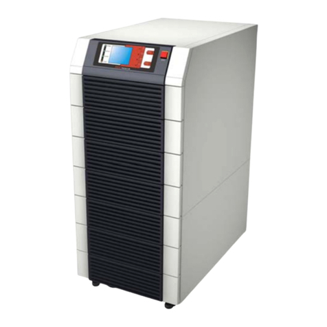
Borealis Series
Three Phase ELI System
8 KW – 48 KW
Installation Manual

**WARNING: ONLY AUTHORIZED FACTORY TRAINED PERSONNEL ARE PERMITTED TO COMMISSION, START UP OR OPERATE THE INVERTER SYSTEM (ELI).
WARRANTY IS VOID IF UNAUTHORIZED PERSONNEL COMMISSION OR START UP THE INVERTER.
M4101_Borealis_8-48Kw_Installation_Manual V1.0 2012-06-14 i

**WARNING: ONLY AUTHORIZED FACTORY TRAINED PERSONNEL ARE PERMITTED TO COMMISSION, START UP OR OPERATE THE INVERTER SYSTEM (ELI).
WARRANTY IS VOID IF UNAUTHORIZED PERSONNEL COMMISSION OR START UP THE INVERTER.
M4101_Borealis_8-48Kw_Installation_Manual V1.0 2012-06-14 ii
NOTE
The instructions contained in this manual are not intended to cover all of the
details or variations in equipment, or to provide for every possible contingency
to be met in connection with installation, operation, or maintenance. Should
further information be desired or should particular problems arise which are not
covered sufficiently for the purchaser’s purposes, the matter should be referred
directly to Always On.
Any electrical or mechanical modifications to this equipment, without prior
written consent of Always On, will void all warranties and may void UL/cUL
listing. Unauthorized modifications may also result in personal injury, death,
and damage to the equipment.
Dear Customer,
Thank you for selecting our emergency lighting inverter (ELI). We are pleased
to include you as one of our valued Always On customers!
We are confident that this emergency lighting inverter system, developed and
manufactured in our ISO 9001 certified facilities, will provide the quality and
satisfaction you demand.
Please read this installation manual carefully as it contains the necessary
information required to install the ELI properly.
Thank you for choosing Always On.

**WARNING: ONLY AUTHORIZED FACTORY TRAINED PERSONNEL ARE PERMITTED TO COMMISSION, START UP OR OPERATE THE INVERTER SYSTEM (ELI).
WARRANTY IS VOID IF UNAUTHORIZED PERSONNEL COMMISSION OR START UP THE INVERTER.
M4101_Borealis_8-48Kw_Installation_Manual V1.0 2012-06-14 iii
Preface
Congratulations on your choice of our emergency lighting inverter (ELI).
This equipment has been manufactured and tested using methods and procedures equivalent to
UL 924.
This manual describes the recommended procedures for installing the ELI.
While every effort has been made to ensure the completeness and accuracy of this manual,
Always On assumes no responsibility or liability for any losses or damages resulting from the
use of the information contained in this document.
WARNING: This manual is intended to provide installation instructions only.
The information contained in this manual is to be used as a guideline and
recommendation only. Only qualified personnel should perform installation
and maintenance. Factory authorized personnel shall inspect installation
prior to start up and commissioning to validate warranty. Failure to follow
this directive will void the warranty.
We recommend that this manual be kept with the ELI for future reference. If any problems are
encountered with the procedures contained in this manual, please contact our Service Centre
before proceeding.
This document may not be copied or reproduced without the explicit written permission of
Always On.
Due to technical advancements and improvements, some of the information contained in this
manual may be changed or modified without prior notice.

**WARNING: ONLY AUTHORIZED FACTORY TRAINED PERSONNEL ARE PERMITTED TO COMMISSION, START UP OR OPERATE THE INVERTER SYSTEM (ELI).
WARRANTY IS VOID IF UNAUTHORIZED PERSONNEL COMMISSION OR START UP THE INVERTER.
M4101_Borealis_8-48Kw_Installation_Manual V1.0 2012-06-14 iv
Symbols
The following symbols are used through out this manual.
Warning Information
This symbol alerts you to important information.
Electrical Hazard
This symbol indicates an electrical hazard may be present.
Electrical Symbols
Protective grounding terminal; a terminal that must be connected to ground prior to
making any other connection to the equipment.
A terminal to/from which an alternating current or voltage may be applied/supplied.
A terminal to/from which a direct current or voltage may be applied/supplied.
This symbol indicates the word “phase”.

**WARNING: ONLY AUTHORIZED FACTORY TRAINED PERSONNEL ARE PERMITTED TO COMMISSION, START UP OR OPERATE THE INVERTER SYSTEM (ELI).
WARRANTY IS VOID IF UNAUTHORIZED PERSONNEL COMMISSION OR START UP THE INVERTER.
M4101_Borealis_8-48Kw_Installation_Manual V1.0 2012-06-14 v
Safety Instructions
READ AND FOLLOW ALL SAFETY INSTRUCTIONS.
SAVE THESE INSTRUCTIONS.
This manual contains important safety instructions that should be followed during installation
and maintenance of the ELI system and optional packages. Before the installation process
begins, we recommend that the installer read through the safety precautions, operators manual
and the option installation instructions, taking all necessary safety precautions to protect
themselves and the equipment being installed.
GENERAL
-Move the ELI in an upright position, in its original packaging, to its final destination.
-To lift the cabinets, use a forklift or lifting belts with spreader bars.
-Check for sufficient floor and elevator loading capacity.
-Check the integrity of the ELI equipment carefully.
-If visible damage is evident, do not attempt to install or start the ELI. Contact the transport
delivery company immediately, file a claim with the transport company and inform Always
On directly.
-Do not use outdoors.
-The use of accessory equipment not recommended by Always On may cause an unsafe
condition
-WARNING! RISK OF ELECTRICAL SHOCK: use extreme caution when removing covers.
-All maintenance and service work should be performed by qualified and trained service
personnel. The ELI may contain its own energy source, (batteries) which can be dangerous
to the untrained person. This ELI contains potentially hazardous voltages
-The field-wiring terminals may be electrically live, even when the ELI is not connected to the
utility.
-Use caution when servicing batteries. A battery can present a risk of electrical shock, burn
from high short-current. Battery acid can cause burns to skin and eyes. If acid is spilled on
skin or in eyes, flush with fresh water and contact physician immediately.
-When replacing batteries use the same number and type (sealed-cell lead acid).
-Proper disposal of batteries is required. Refer to your local codes for disposal requirements.
-Dangerous voltages may be present during battery operation. The batteries must be
disconnected during maintenance or service work. (Open battery breaker or fuses)
-Be aware that the inverter can restart automatically after the utility voltage is restored.
-Do not use this equipment for other than intended use.

**WARNING: ONLY AUTHORIZED FACTORY TRAINED PERSONNEL ARE PERMITTED TO COMMISSION, START UP OR OPERATE THE INVERTER SYSTEM (ELI).
WARRANTY IS VOID IF UNAUTHORIZED PERSONNEL COMMISSION OR START UP THE INVERTER.
M4101_Borealis_8-48Kw_Installation_Manual V1.0 2012-06-14 vi
INSTALLATION
-This ELI is intended for use in a controlled indoor environment free of conductive
contaminants and protected against any type of intrusion.
-Do not install the ELI in an excessively humid environment or near water.
-Avoid spilling liquids and/or dropping any foreign object(s) onto the ELI.
-The unit must be placed in a sufficiently ventilated area; the ambient temperature should not
exceed 40°C (104°F).
-Optimal battery life is obtained if the ambient temperature does not exceed 25°C (77°F).
-HIGH GROUND LEAKAGE CURRENT: ground connection completed before connecting the
AC voltage wires on the input!
-Switching OFF the ELI does not isolate the ELI from the utility as the utility supply is still
HOT at the input terminal strip. Supply breaker needs to be opened.
-It is important that air can move freely around and through the unit. Do not block the air
vents.
-Avoid locations in direct sunlight or near heat sources (gas or electric heaters).
STORAGE
-Store the ELI in a dry location free of contaminants;
-Storage temperature must be within -25°C (-13°F) to 55°C (131°F).
- If the unit is stored for a period exceeding 3 months, the batteries must be recharged
periodically (time depending on storage temperature).
WARNING!
LETHAL VOLTAGES MAY BE PRESENT WITHIN THIS UNIT EVEN WHEN IT IS
APPARENTLY NOT OPERATING. OBSERVE ALL CAUTIONS AND WARNINGS IN THIS
MANUAL. FAILURE TO DO SO COULD RESULT IN SERIOUS INJURY OR DEATH. REFER
UNIT TO QUALIFIED SERVICE PERSONNEL IF MAINTENANCE IS REQUIRED. NO ONE
SHOULD WORK ON THIS EQUIPMENT UNLESS THEY ARE FULLY QUALIFIED TO DO SO.
AN INSTALLER SHOULD NEVER WORK ALONE.
WARNING!
WHEN REMOVING POWER FROM THE ELI, ALLOW FIVE MINUTES FOR CAPACITORS
TO DISCHARGE BEFORE WORKING ON THE EQUIPMENT.
CAUTION!
This equipment complies with the requirements in Part 15 of FCC rules for a Class A
computing device. Operation of this equipment in a residential area may cause
interference to radio and TV reception, requiring the operator to take whatever steps
necessary to correct the interference.
CAUTION!
Do not put option control wiring in the same conduit as the ELI input or output power
cables.

**WARNING: ONLY AUTHORIZED FACTORY TRAINED PERSONNEL ARE PERMITTED TO COMMISSION, START UP OR OPERATE THE INVERTER SYSTEM (ELI).
WARRANTY IS VOID IF UNAUTHORIZED PERSONNEL COMMISSION OR START UP THE INVERTER.
M4101_Borealis_8-48Kw_Installation_Manual V1.0 2012-06-14 vii
THIS SAFETY NOTICE IS ADDRESSED TO THE ALWAYS ON
CUSTOMER ENGINEERS WHO PERFORM MAINTENANCE OF THE
UNINTERRUPTIBLE POWER SUPPLY (ELI) SYSTEMS.
Electrical Safety
•Maintenance work to be performed by a factory trained customer engineers, or qualified
personnel. Extremely dangerous voltage levels can exist within the ELI system. Extreme
caution must be used.
•Ensure system is in maintenance bypass mode or external wrap-around bypass mode
before work is started.
•This manual is designed as an aid tool in diagnosing problems that may arise. Always
On does not assume responsibility if information causes injuries.
•Apart from the front door, do not open any other part of the ELI without consulting the
factory first. Before removing the protection screens, be sure that the unit is completely
powered off.
•Be aware that dangerous voltage can be supplied by the internal battery or electrolytic
capacitors.
•When system is in bypass mode and all fuses have been opened dangerous voltages
may exist within the ELI system. Use extreme caution when exchanging boards and
working inside the unit.
READ AND FOLLOW ALL SAFETY INSTRUCTIONS.
SAVE THESE INSTRUCTIONS.

**WARNING: ONLY AUTHORIZED FACTORY TRAINED PERSONNEL ARE PERMITTED TO COMMISSION, START UP OR OPERATE THE INVERTER SYSTEM (ELI).
WARRANTY IS VOID IF UNAUTHORIZED PERSONNEL COMMISSION OR START UP THE INVERTER.
M4101_Borealis_8-48Kw_Installation_Manual V1.0 2012-06-14 viii
TABLE OF CONTENTS
1. Introduction..................................................................................................................................1
1.1. Overview.....................................................................................................................1
1.2. Features......................................................................................................................1
1.3. Definitions..................................................................................................................2
2. Handling ........................................................................................................................................3
2.1. Transport....................................................................................................................3
2.2. Delivery.......................................................................................................................3
2.3. Storage........................................................................................................................3
2.4. Unpacking..................................................................................................................4
3. Physical Topology......................................................................................................................5
4. Installation ....................................................................................................................................8
4.1. Site & Environmental Conditions........................................................................8
4.2. Cable Selection.......................................................................................................10
4.3. Terminal Strip Connections................................................................................11
4.4. Skirting Installation ...............................................................................................12
5. ELI AND BBU WIRING DIAGRAMS.......................................................................................13
6. INTERFACE CONNECTIONS..................................................................................................18
6.1. Dry Contacts............................................................................................................18
6.2. Software for PC Monitoring.................................................................................19
6.3. Emergency Power off Connection.....................................................................19
6.4. DB9 Connectors.....................................................................................................19
6.5. Web Monitoring Module (SNMP Module).........................................................19
6.6. Emergency Lighting Notification.......................................................................20
7. Battery Backup Units (BBU)...................................................................................................22
7.1. Run Time Charts.....................................................................................................24
7.2. BBU Configurations ..............................................................................................26
8. Technical Specifications.........................................................................................................28
9. Contact Information..................................................................................................................32

**WARNING: ONLY AUTHORIZED FACTORY TRAINED PERSONNEL ARE PERMITTED TO COMMISSION, START UP OR OPERATE THE INVERTER SYSTEM (ELI).
WARRANTY IS VOID IF UNAUTHORIZED PERSONNEL COMMISSION OR START UP THE INVERTER.
M4101_Borealis_8-48Kw_Installation_Manual V1.0 2012-06-14 1
1. Introduction
Congratulations on your choice of the Borealis On-Line Emergency Lighting Inverter (ELI). This
ELI features the latest top of the line microprocessor technology and IGBT transistors and
provides clean, highly regulated and pulse width modulated (PWM) true sine wave power.
1.1. Overview
This ELI is designed for installation between your AC power supply (utility or generator)
and your lighting equipment. It provides power to your equipment during major power
events such as blackouts and brownouts, over-voltage and under-voltage conditions.
The ELI provides a consistent supply of regulated AC power during these power events,
allowing you to ensure safety and lighting for the period required.
1.2. Features
This ELI provides full time self-diagnostics as well as two levels of audible alarms when
the unit is operating in battery mode. Along with the current mode of operation, the LCD
screen displays critical system information including:
•Percent Load
•Remaining battery capacity, battery voltage
•Input voltage,
•Output voltage,
•Input frequency,
•Output frequency and
•Internal ELI temperature.
A manual test switch has been incorporated into the input/test breaker that makes
testing a simple procedure. The internal bypass switch allows maintenance on the ELI to
be performed without interruption of power to the load.
The communications port, in conjunction with multi-platform monitoring and control
software, enables the unit to be connected to a local or networked computer system.
Detailed operating information including voltages, currents, and alarm status is available
to the monitoring system.
Other communications options include:
•An SNMP adapter to remotely control and monitor the unit via a network or the
Internet.
•An AS-400 interface to allow for relay communications in PLC or dry contact
environments.

**WARNING: ONLY AUTHORIZED FACTORY TRAINED PERSONNEL ARE PERMITTED TO COMMISSION, START UP OR OPERATE THE INVERTER SYSTEM (ELI).
WARRANTY IS VOID IF UNAUTHORIZED PERSONNEL COMMISSION OR START UP THE INVERTER.
M4101_Borealis_8-48Kw_Installation_Manual V1.0 2012-06-14 2
1.3. Definitions
•Critical Load
These are loads that require clean, regulated and continuous AC power and
which are connected to the output of the ELI module
•ELI Module
The portion of the ELI system that contains one or more of: the rectifier / DFC,
charger, inverter, static bypass switch, maintenance bypass switch, controls,
monitoring, and indicators.
•Rectifier / DFC
Contained in the ELI module. Responsible for converting the normal AC input
power to DC power and supplying the inverter with DC power.
•Charger
Contained in the ELI module. Responsible for recharging the batteries.
•Inverter
Contained in the ELI module. Responsible for converting DC power (supplied by
the rectifier) to regulated and filtered AC power that is then supplied to the critical
loads.
•Static Bypass Switch
Contained in the ELI module. Responsible for automatically transferring the
attached load, without interruption, from the inverter AC output to the bypass AC
power source in the event of an overload or degradation of the inverter’s
performance.
•Maintenance Bypass Switch:
Contained in the ELI module. Used to transferring the attached load, without
interruption, from the inverter AC output to the bypass AC power source while
electrically isolating the static bypass switch, rectifier / DFC, charger and inverter.
Used for maintenance purposes.
•Battery
The battery system provides DC power to the inverter input when the normal AC
input power to the ELI fails.
•IGBT
Isolated Gate Bipolar Transistor.
•PWM
Pulse Width Modulation.
•ELI
Emergency Lighting Inverter.
•BBU
Battery Backup Unit.
•PFC
Power Factor Correction.
•EPO
Emergency Power Off.

**WARNING: ONLY AUTHORIZED FACTORY TRAINED PERSONNEL ARE PERMITTED TO COMMISSION, START UP OR OPERATE THE INVERTER SYSTEM (ELI).
WARRANTY IS VOID IF UNAUTHORIZED PERSONNEL COMMISSION OR START UP THE INVERTER.
M4101_Borealis_8-48Kw_Installation_Manual V1.0 2012-06-14 3
2. Handling
2.1. Transport
The ELI is packaged on a pallet, suitable for handling with a forklift.
Pay strict attention to the center of gravity. The ELI must be moved in upright position.
Do not tilt cabinets more than +/- 10° during handling.
Move the ELI in its original package to the final destination site.
Do not stack other packages on top.
If the ELI must be lifted by crane, use suitable lifting straps and spreader bars.
2.2. Delivery
Upon receiving the ELI system, inspect the packaging integrity and the physical
condition of the cabinets carefully.
In the event that physical damage is visible, the carrier must be informed immediately
and a claim filed with them. Inform Always On as soon as the claim has been filed.
A detailed report of the damage is necessary for carrier insurance claim.
WARNING
A damaged ELI system must never be installed or connected to the utility or batteries without
written instruction from Always On Engineering.
2.3. Storage
The ELI is carefully packed for transport and storage.
Never leave an ELI outside the building exposed to the elements and do not place other
packages on the top of the ELI.
Storing: It is recommended to store the ELI in its original package in a dry, dust-free
room, away from chemical substances, and with a temperature range of -25°C (-13°F)
to 55°C (131°F). Exceeding this temperature range may cause damage and will void the
warranty.
BATTERY STORAGE AND SHELF LIFE
Although this system includes maintenance free batteries, keep in mind that they are
subject to self-discharge and therefore must be recharged at regular intervals.

**WARNING: ONLY AUTHORIZED FACTORY TRAINED PERSONNEL ARE PERMITTED TO COMMISSION, START UP OR OPERATE THE INVERTER SYSTEM (ELI).
WARRANTY IS VOID IF UNAUTHORIZED PERSONNEL COMMISSION OR START UP THE INVERTER.
M4101_Borealis_8-48Kw_Installation_Manual V1.0 2012-06-14 4
The storage time without battery recharge depends on the temperature of the storage
site. The optimal temperature for battery storage is 20°C (68°F) to 25°C (77°F). If
batteries are not recharged at the recommended intervals warranty will be void.
Recharge of the stored maintenance free battery should occur every:
6 months when the ambient storage temperature is 20°C (68°F)
3 months when the ambient storage temperature is 30°C (86°F)
2 months when the ambient storage temperature is 35°C (95°F)
2.4. Unpacking
Carefully remove all the packaging material of the ELI, then carefully place the ELI at the
final destination site.
This ELI system has passed all stages of production testing and final stage QC testing
prior to shipment from the factory (report enclosed). The ELI should be in full operating
condition upon receipt. Upon receiving visually check the ELI for any physical
damage that may have occurred during transport. If damage is noticed file a damage
report immediately with the transport company and inform Always On.
Also check to ensure all of the accessories/options ordered are received.
Check and verify the specifications of the ELI are identical to the specifications of the
system ordered. The key items in the specifications you must check are:
•RATED POWER OF THE ELI
•INPUT VOLTAGE & FREQUENCY
•OUTPUT VOLTAGE & FREQUENCY
•BATTERY RUNTIME

**WARNING: ONLY AUTHORIZED FACTORY TRAINED PERSONNEL ARE PERMITTED TO COMMISSION, START UP OR OPERATE THE INVERTER SYSTEM (ELI).
WARRANTY IS VOID IF UNAUTHORIZED PERSONNEL COMMISSION OR START UP THE INVERTER.
M4101_Borealis_8-48Kw_Installation_Manual V1.0 2012-06-14 5
Figure 3.1
Front view of system with
Door Closed
Figure 3.2
Front view of system with Door Open
3. Physical Topology
1.TurnofftheINVERTERmodulebyP pressing &
on theLCDpanelP simultaniously.P2.Openthe
BATTERYbreaker/P fuses.P3.Openthe RECTIFIER
breaker.P4.Wait5minutesfor DC Pcapacitorto
discharge.P5.Open theRESERVEbreaker.P6.Open
theINPUTbreaker.P7. Lockthedoor.
1.ClosetheINPUTbreaker.P2.Close theRESERVE
breaker.P3.Close theRECTIFIERbrea ker.P4.Wait30
secoundfortheDC busP voltagetorise.Thewarning
LEDsP "BATLOW"and'BATLOW STOP"P on thefront
panelwillturnoff.P5.Closethe BATTERYbreaker/P
fuses.P6. Startthe INVERTERmoduleb yP pressing &
on theLCDpanelP simultaniously.P7.Theload will
transferto inverterP output in approxima tely 7
secon ds.P8. Lockthedoor.
OperatingProcedure
Warning:ForInstallation&FirstTimeStartup,PleaseSe
Star tu p Procedure Shut d o w n Proc e d u re
Inverterto Manual Bypa ss Proce d ure Manual Bypassto InverterPProcedure
1.Turnoff the INVERTERmodulebyP pressing &
on theLCDpanelP simultaniously.P2.Openthe
BATTERYbreaker/P fuses.P3.Openthe RECTIFIER
breaker.P4.Wait 5 minu tes for DCcapa c itorsP to
discharge.P5.Closethebypassbreaker. P6.Open
theReservebreaker.P7.TheUPSisnowinmanual
bypass.
1.CloseallfusesbehindthecontrolP module door.P2.
Close the RESERVEbreaker.P3.Openthe Bypass
breakerP4.Close the RECTIFIERbreaker.P5.Wait30
seconds for the DC busP v oltage to rise.The warning
LEDsP "BATLOW"a nd 'BATLO W STOP"P on thef ront
panelwillturnoff.P6.ClosetheBATTERYbreaker/P
fuses.P7. Startthe INVERTERmoduleb yP pressing &
on theLCDpanelP simultaniously.P8.Theload will
transferto in verterP outputin ap proxima tely 7
seconds.P9.Lockthe door.
Before Maintenance beginsPOnUPS
1.Openall fusesbehindthecontrolPmodule
door.
WARNING
!
Dange ro us AC & DCPHIGH
VOLTAGE!
INPUT RECTIFIER RESERVE BYPASS
ELI Rating Dimensions Weight
(KW) W (Width) D (Depth) H (Height) ELI Floor Loading
8 559mm (22") 815mm (32.0") 1,600mm (63.0") 380kg (838lbs) 864 kg/sq.m (177 lbs/sq.ft.)
12 559mm (22") 815mm (32.0") 1,600mm (63.0") 415kg (915lbs) 943 kg/sq.m (193 lbs/sq.ft)
16 559mm (22") 815mm (32.0") 1,600mm (63.0") 450kg (992lbs) 1,023 kg/sq.m (210 lbs/sq.ft)
24 559mm (22") 815mm (32.0") 1,600mm (63.0") 580kg (1,279lbs) 1,318 kg/sq.m (270 lbs/sq.ft.)
32 559mm (22") 815mm (32.0") 1,600mm (63.0") 650kg (1,433lbs) 1,477 kg/sq.m (303 lbs/sq.ft.)
40 559mm (22") 815mm (32.0") 1,600mm (63.0") 710kg (1,565lbs) 1,614 kg/sq.m (330 lbs/sq.ft)
48 1,100mm (43.25") 815mm (32.0") 1,600mm (63.0") 920kg (2,024lbs) 1,672 kg/sq.m (207 lbs.sq.ft.)

**WARNING: ONLY AUTHORIZED FACTORY TRAINED PERSONNEL ARE PERMITTED TO COMMISSION, START UP OR OPERATE THE INVERTER SYSTEM (ELI).
WARRANTY IS VOID IF UNAUTHORIZED PERSONNEL COMMISSION OR START UP THE INVERTER.
M4101_Borealis_8-48Kw_Installation_Manual V1.0 2012-06-14 6
AC
O/PSS O/P O/P
PS
LOWER FAN
PS R S T
CAP
CAP
CAP
OSIRIN ITIS ORB+OTONB-
CNT2
CNA11
CNB6
CNA7
CNT3 GCNT4 R CNT3 CNT 4 R G CNT3
CNT5
CNT5
CNA4
CNT1
CNA10CNA9
CNT2
CNT1
CNT2
CNT1
CNA8
CNC3 CNC4
CNC1 CNB2CNB1
CNT4 GR
CNT5
RS232 RS485
3R
CNR1
CNA1
CNR5
CNR4
CNA5 CNA2
RELAY I NTERFACE
CNR7
MIMICPANEL
LCD PANEL
& SWITCHES
LE D PANEL
WARNING
CNB5
CNB7
& BEEPER
LED PANEL
STATUS
CNB6
MODULE
TO S.S.
BLUWHTRED
TO INV.
3B
3C
3A
3T
TO REC.
MODULE
RECTI F I ER CONT ROLPOWER SUPPLY
MAI N CONTROL
INVERTERPHASE
CONTROL
(R PHASE)
3T
INVERTERPHASE
CONTROL
(S PHASE)
3T
INVERTERPHASE
CONTROL
(T PHASE)
MODULE
COMMUNI CATI ONS
INTERFACE
R
R
GR
R
R
R
G
RG
R
Y
G
R
G
R
Figure 3.3
Front view of system with Door Open,
PCB Module fully open and terminal
strip cover off
Figure 3.4
Front view of system with Door
Open and PCB Module door open

**WARNING: ONLY AUTHORIZED FACTORY TRAINED PERSONNEL ARE PERMITTED TO COMMISSION, START UP OR OPERATE THE INVERTER SYSTEM (ELI).
WARRANTY IS VOID IF UNAUTHORIZED PERSONNEL COMMISSION OR START UP THE INVERTER.
M4101_Borealis_8-48Kw_Installation_Manual V1.0 2012-06-14 7
Figure 3.5
Front, Side & Top Views of the System
559mm [22”]
815mm [32”]
1600mm [63"]

**WARNING: ONLY AUTHORIZED FACTORY TRAINED PERSONNEL ARE PERMITTED TO COMMISSION, START UP OR OPERATE THE INVERTER SYSTEM (ELI).
WARRANTY IS VOID IF UNAUTHORIZED PERSONNEL COMMISSION OR START UP THE INVERTER.
M4101_Borealis_8-48Kw_Installation_Manual V1.0 2012-06-14 8
4. Installation
4.1. Site & Environmental Conditions
The designed function of the ELI is to provide a safe, clean and independent electrical
supply free from random variations, disturbances or interruptions of the utility mains. The
ELI will provide a constant power source, which is regulated in both voltage and
frequency. When the utility mains are not available, the ELI will provide optimal back-up
time depending on the capacity connected battery bank.
Usually the life expectancy of the ELI is 8 to 10 years. The optimal life expectancy of the
ELI can be achieved by careful consideration of the site and environment.
The following precautions and recommendations should be checked when considering
the site and environment for the ELI:
a. The ELI should be located in a place with adequate ventilation (refer to the
specification of the heat dissipation of the ELI). Should the ELI be installed in a sealed
room, care must be taken to ensure adequate heat evacuation is provided.
71"
35"
25"
76"
52"
34"
2'
3'
Figure 4.1
Minimum S
p
acin
g
Re
q
uirement
s

**WARNING: ONLY AUTHORIZED FACTORY TRAINED PERSONNEL ARE PERMITTED TO COMMISSION, START UP OR OPERATE THE INVERTER SYSTEM (ELI).
WARRANTY IS VOID IF UNAUTHORIZED PERSONNEL COMMISSION OR START UP THE INVERTER.
M4101_Borealis_8-48Kw_Installation_Manual V1.0 2012-06-14 9
b. Void space is not required on all sides of the ELI system, but adequate space, a
minimum of 1m (3’), should be allowed for the door to open. Adequate space, a
minimum of 60cm (2’) [recommended 1m (3’)], should also be allowed at the top of the
ELI system to allow for proper heat dissipation and ventilated through the top openings
(optional ventilation booth is available upon request). Leave a minimum of 2 feet on
right hand side of ELI.
c. The battery banks require access to front only.
d. Do not place any objects on the top of the ELI that might obscure the ventilation. Do
not place the ELI near any heat source, or machinery, which may produce metallic
particles, dust or powder. Do not place the ELI near equipment that will produce
corrosive substances or vapor.
e. Do not place the ELI below the shower of a fire extinguishing system (optional drip
shield available). Abnormal conditions of the ELI should be protected by a cutoff from the
power supply.
f. The user is required to guarantee the temperature and humidity values of the site
into which the ELI will be installed meet the required and published manufacturer
specifications. The ELI should be installed within the range allowed by these
specifications. The ELI is capable of continuous normal operation within a temperature
range of 0°C (32°F) to 40°C (104°F). For optimal performance and reliability the
recommended environment temperature is best at 25°C, with humidity 0 to 95% non-
condensing.
g. The floor loading capacity should be sufficient to endure the weight of the ELI. Four
right-angled steel feet attached restrainers are included with the ELI system, which
should be inserted into the floor for securing the ELI system, when the location has the
potential to experience vibrations. (e.g.: earthquake, moving vehicles, or tanker.) The
locations and layout of the restrainers are shown below.
h. Walls, ceilings, floors or anything near to the ELI should be constructed of non-
combustible materials. A portable fire extinguisher should be accessible nearby.
i. Avoid accumulating litter or trash of any sort in or around the ELI system. The floor
area surrounding the ELI should be kept clean, free from metallic powder and/or filings.
j. Access to the ELI room should be limited to operation and maintenance personnel.
The doors should be kept locked and the keys should be available only to authorized
personnel.
k. Personnel who operate or maintain the ELI system should be proficient in normal
and emergency operational procedures. New personnel should be trained and qualified
prior to operation of the equipment.
l. Although the ELI has passed the international EMC tests, it is not recommended to
install the ELI near to any equipment that is susceptible to electro-magnetic interference,
such as computer systems, monitors, radios etc.
m. The system should be connected to the emergency generator, if available.

**WARNING: ONLY AUTHORIZED FACTORY TRAINED PERSONNEL ARE PERMITTED TO COMMISSION, START UP OR OPERATE THE INVERTER SYSTEM (ELI).
WARRANTY IS VOID IF UNAUTHORIZED PERSONNEL COMMISSION OR START UP THE INVERTER.
M4101_Borealis_8-48Kw_Installation_Manual V1.0 2012-06-14 10
n. The system, when installed in a sprinkler-equipped room, must have a sprinkler
guard installed.
4.2. Cable Selection
The cabling of the ELI system has to be sized according to the ELI power rating.
Sizing of circuit breakers, fuses and cables for input utility, output load and battery must
meet the requirements of local and national electrical codes.
Refer to Section 10 for technical specifications.
WARNING
Inadequate cable size and over sized breakers can increase the risk of fire or damage
connection cables and internal components.

**WARNING: ONLY AUTHORIZED FACTORY TRAINED PERSONNEL ARE PERMITTED TO COMMISSION, START UP OR OPERATE THE INVERTER SYSTEM (ELI).
WARRANTY IS VOID IF UNAUTHORIZED PERSONNEL COMMISSION OR START UP THE INVERTER.
M4101_Borealis_8-48Kw_Installation_Manual V1.0 2012-06-14 11
4.3. Terminal Strip Connections
NLINE
1 LINE
2
LINE
3
3 PHASE INPUT/ 3 PHASE OUTPUT
TERM INAL WITH SING LE SO URC E
INPUT
RECTIFIER & RESERVE
IN IR ORIT
IS
ELI
OUTPUT
OS OT
BATTERY
INPUT
B-
ON B+ G
BLACK
RED
G
GREEN
N
WHITE
LINE
3
BLUE
LINE
1
RED
LINE
2
BLACKBLUE
BAT
-
BLACK
BAT
+
RED
WHITE
FIRE ALARM
CONNECTION
*CAUTION: REMOVE THE NEUTRAL BONDING JUMPER IF ELI IS CONNECTED TO AN
EXTERNAL BYPASS SYSTEM.
3 PHASE INPUT/ 3 PHASE OUTPUT
TERM INAL WITH SING LE SO URC E
INPUT
RECTIFIER & RESERVE
IN IR ORITIS
ELI
OUTPUT
OS OT
BATTERY
INPUT
B-
ON B+ G
*
CONNECTION
FIRE ALARM
Table of contents
Other Always “On” UPS UPS manuals

Always “On” UPS
Always “On” UPS GES-325V User manual

Always “On” UPS
Always “On” UPS Limousin II User manual

Always “On” UPS
Always “On” UPS GES-701N - GES-302N ABS User manual

Always “On” UPS
Always “On” UPS GES-801V User manual

Always “On” UPS
Always “On” UPS GES-242NX-R Setup guide

Always “On” UPS
Always “On” UPS DC UPS Systems User manual