Avaya 4500 VA Setup guide

Site Preparation,
Installation and Operator’s Manual
for
Avaya
Avaya Series 1
Uninterruptible Power Systems
Models 4500/5000/6000 VA
Select Code 167-405-115

USPatents 6,069,412
5,469,098
4,980,812
Requesting a Declaration of Conformity
Units that are labeled with a CE mark comply with the following harmonized standards and EU directives:
S
Harmonized Standards: EN 50091-1-1 and EN 50091-2
S
EU Directives: 73/23/EEC, Council Directive on equipment designed for use within certain voltage limits
93/68/EEC, Amending Directive 73/23/EEC
89/336/EEC, Council Directive relating to electromagnetic compatibility
92/31/EEC, Amending Directive 89/336/EEC relating to EMC
The EC Declaration of Conformity is available upon request for products with a CE mark. For copies of the EC
Declaration of Conformity, contact:
Powerware Corporation
Koskelontie 13
FIN-02920 Espoo
Finland
Phone: +358-9-452 661
Fax: +358-9-452 665 68
Class A EMC Statements
FCCPart 15
NOTE This equipment has been tested and found to comply with the limits for a Class A digital device, pursuant to
part 15 of the FCC Rules. These limits are designed to provide reasonable protection against harmful interference when
the equipment is operated in a commercial environment. This equipment generates, uses, and can radiate radio frequency
energy and, if not installed and used in accordance with the instruction manual, may cause harmful interference to radio
communications. Operation of this equipment in a residential area is likely to cause harmful interference in which case
the user will be required to correct the interference at his own expense.
EN50091-2
Some configurations are classified under EN50091-2 as “Class-A UPS for Unrestricted Sales Distribution.” For these
configurations, the following applies:
WARNING This is a Class A-UPS Product. In a domestic environment, this product may cause radio interference, in
which case, the user may be required to take additional measures.
DEFINITY is a registered trademark of Avaya Inc.
IBM and AS/400 are registered trademarks of International Business Machines Corp.
Novell is a registered trademark of Novell, Inc.
3Com is a registered trademark of 3Com Corporation.
E
Copyright 2001 Avaya Inc. All rights reserved. No part of this document may be reproduced in any way without the
express written approval of Avaya Inc.

Site Preparation,
Installation and Operator’s Manual
for
Avaya
Avaya Series 1
Uninterruptible Power Systems
Models 4500/5000/6000 VA
Select Code 167-405-115
Issue 5
Copyright 2001 Avaya Inc.
All Rights Reserved

Special Symbols
The following are examples of symbols used on the UPS to alert you to important information:
LOAD ON – Press the button with this symbol to energize the output receptacles
(Output On).
LOAD OFF – Press the button with this symbol to de-energize the output
receptacles (Output Off).
SAFETY EARTHING TERMINAL – Indicates the primary safety ground.
RISK OF ELECTRIC SHOCK – Indicates that a risk of electric shock is present and
the associated warning should be observed.
CAUTION: REFER TO OPERATOR’S MANUAL – Refer to your operator’s manual for
additional information.
INPUT BREAKER – Indicates the input breaker, which shuts off utility power to
the PPU.
BATTERY BREAKER – Indicates the battery breaker, which shuts off battery power
(power transmission through the battery cord) when in the OFF (O) position.
BATTERY CONNECTOR – Indicates the battery connector, which remains
electrically “hot” even with the battery breaker off. Keep covered when not in
use.
INPUT – Indicates the input to a unit.
OUTPUT – Indicates the output from a unit.
BYPASS – Indicates bypass control switches.

2
3
4
UPS WITH BDM QUICK INSTALLATION
CAUTION
Read the safetyinstructionsbeginning on page 5 before installing the UPS.
1
Desired Output
Voltage Voltage SelectorPosition
100/200V 200
110/220V 220
115/230V 230
120/240V 208 if UPS Input is 208V
240 if UPS Input is 240V

UPS with BDM Quick Installation
5
6
7
89

i
Avaya Model 6000 UPS Operator’s Manual
S
167-405-115 Issue 5 Uncontrolled Copy
TABLE OF CONTENTS
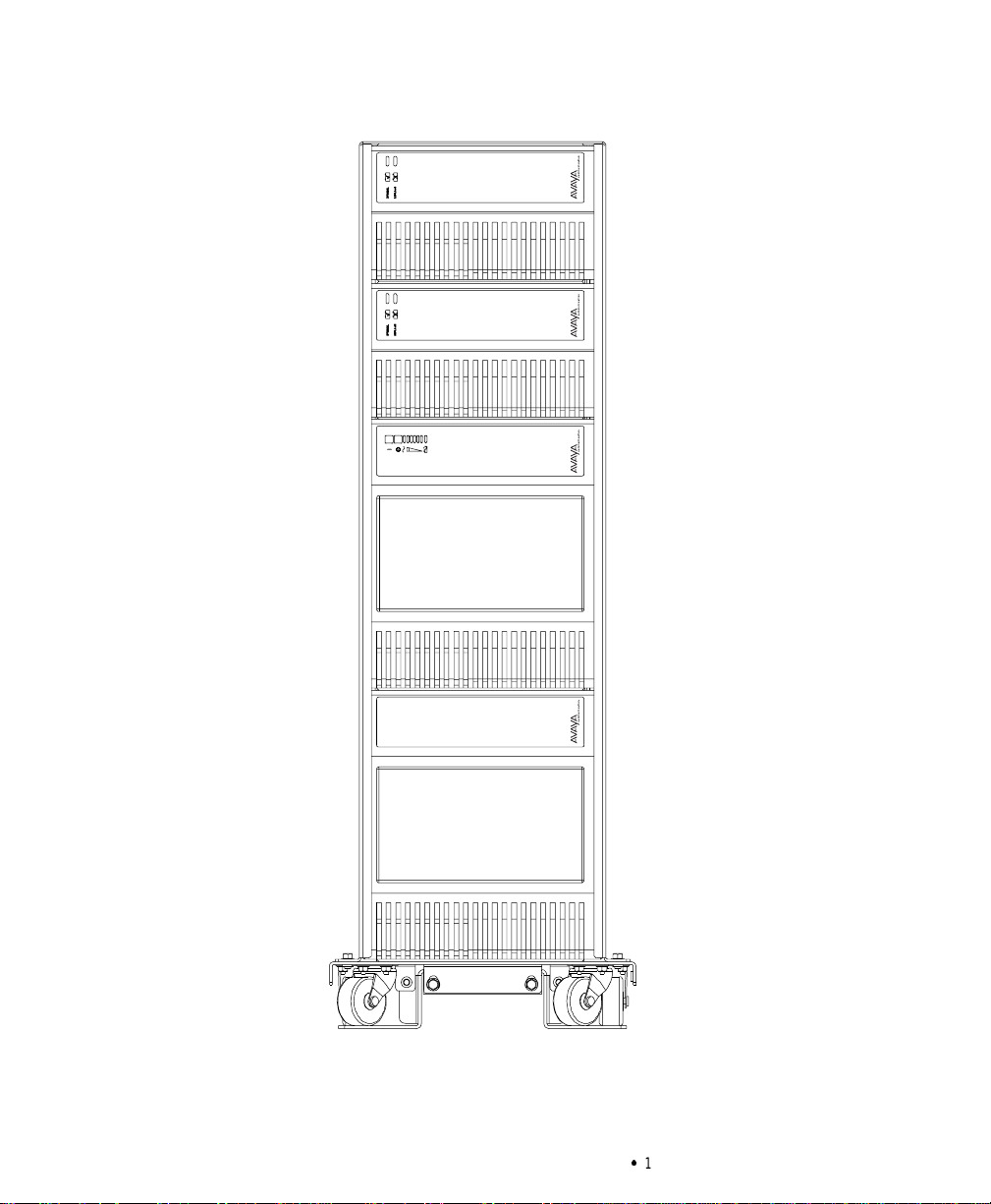
1 Introduction 1....................................................
UPSModel and Battery Configurations 3..............................................
Load Requirements 3.........................................................
BatteryTimes 4.............................................................
2 Safety Warnings 5.................................................
3 Installation 23.....................................................
Unpacking and Inspection 23.......................................................
UPSand BatteryModule Storage 23...............................................
ImportantInstallation Notes– Read Before Installing the UPS 23...........................
SystemsThat Require Contact Closure 24...........................................
SystemsThat Require a Serial Interface 24..........................................
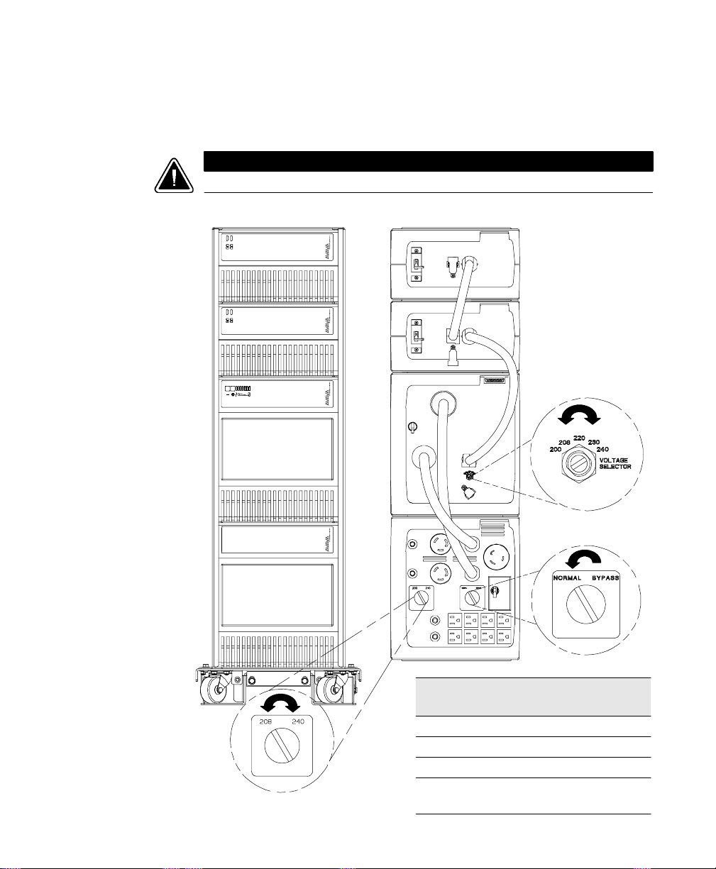
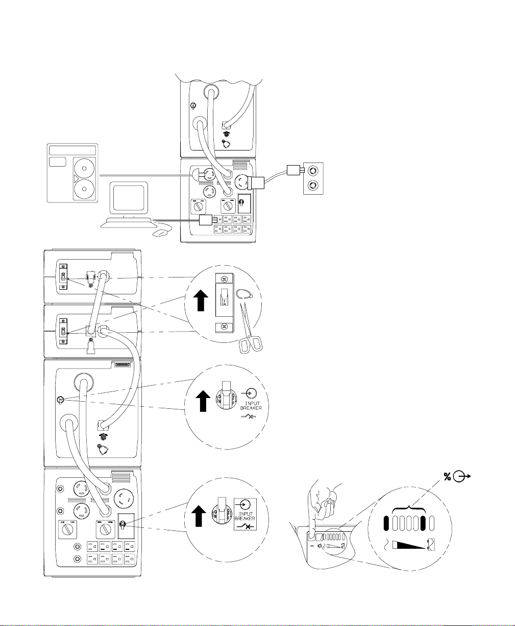
Installing the UPS 24.............................................................
REPOInstallation 35...........................................................
UPS with BDM Startup 37.......................................................
Troubleshooting Tips 39..........................................................
EPDM Configurations 40..........................................................
4 UPS Operation 41..................................................
UPS Front Panel 41..............................................................
Operating Modes 42.............................................................
NormalMode 42.............................................................
BypassMode 43.............................................................
BatteryMode 43.............................................................
Diagnostics 44.................................................................
Battery Test on Demand 44......................................................
BatteryStart 44................................................................
UPSShutdown 45...............................................................
Changing the Output Voltage 45.....................................................
Using the BDM 46...............................................................
Using Maintenance Bypass 46....................................................

Table of Contents
ii Avaya Model 6000 UPS Operator’s Manual
S
167-405-115 Issue 5 Uncontrolled Copy
5 Communication 51.................................................
InitialCommunicationsSettings 51...................................................
Front PanelCommunicationsAccess 52...............................................
UPSSerialCommunicationsMenu 54.................................................
UPSCommunicationsInterface Port 57................................................
CommunicationsMode Reference Chart 59.............................................
6 Specifications 61..................................................
Model 6000 Specifications 61......................................................
UPS Physical Specifications 62......................................................
UPSTechnicalSpecifications 63.....................................................
Electrical Specificationsfor the Model6000 with BDM 64..................................
7 Troubleshooting 67.................................................
Resetting the UPS 69............................................................
Silencing the Alarm 69...........................................................
Service and Support 69...........................................................
PartsList 70...................................................................
Index 71.........................................................

1
Avaya Model 6000 UPS Operator’s Manual
S
167-405-115 Issue 5 Uncontrolled Copy
CHAPTER 1
INTRODUCTION
Congratulations on the purchase of your Avaya Series 1 uninterruptible
power system (UPS). The UPS meets the toughest measures of superior
design and manufacturing, including ISO 9001. You now own the most
reliable power protection available.
This family of UPS systems provides a steady, well-regulated power
supply for your computing and communications equipment, while
protecting it from the frequent irregularities that are inherent in
commercially available power.Voltage spikes,power surges,brownouts,
and power failures have the potential to corrupt critical data, destroy
unsaved work sessions, and in some instances, damage expensive
hardware.
Now you can safely eliminate the effects of electrical line disturbances
and guard the integrity of your systems and equipment. The Bypass
Distribution Module (BDM) has a Maintenance Bypass feature that
supplies power to your equipment even when the power processing
unit (PPU) is removed for maintenance or upgrades. Figure 1 shows the
Model 6000 UPS with two battery modules, a PPU, and a BDM.
In addition, an Extended Battery Cabinet (EBC) may be configured. The
installation of this product and connection to the battery modules is
covered by a separate document shipped with the EBC.

Introduction
2Avaya Model 6000 UPS Operator’s Manual
S
167-405-115 Issue 5 Uncontrolled Copy
Figure 1. Model 6000 UPS

Introduction
3
Avaya Model 6000 UPS Operator’s Manual
S
167-405-115 Issue 5 Uncontrolled Copy
UPS Model and Battery Configurations
There are two important considerations when selecting the UPS model
and battery configuration to properly safeguard your equipment:
S
Load requirements
S
Battery times
NOTE Do not connect more than sixstandard battery modules to the PPU. For
extended batterytimes,contact your Avaya Inc.representative.
Load Requirements
The load is the equipment to be protected by the UPS.Select the UPS
model that meets the power consumption requirements of the load in
volt-amperes (VA). The total load VA should not exceed the UPS VA
rating. To determine the total load requirements:
1. Obtain the load ratings from either the nameplate or operator’s
manual of the equipment to be protected by the UPS. The
ratings are listed in either watts (W), amperes or amperes
max (A), or volt-amperes (VA).
2. If the rating is in watts, multiply by 1.4 to obtain the VA
requirement (this is the typical relationship between watts and
volt-ampere ratings in most computing equipment). However,
in some new computing equipment, the power supply is
power-factor corrected and the watts rating equals the VA
requirement. Check with the manufacturer to determine
applicability.
If the rating is in amperes or amperes max, multiply by the
input voltage to obtain the VA requirement.

Introduction
4Avaya Model 6000 UPS Operator’s Manual
S
167-405-115 Issue 5 Uncontrolled Copy
3. Add all of the resultant VA ratings together to obtain the total
load requirements of the equipment to be protected (see
Figure 2). If the load consists of the power-factor corrected
supplies, it is recommended to use total watts for the load
requirements.
3 COMPUTERS 3 MONITORS EXTERNAL
MODEM
3 x 300 WATTS X 1.4 = 1260 VA 3x2AMPSx240V = 1440 VA 50 VA
1260 VA + 1440 VA + 50 VA = 2750 VA (Total Load Requirements)
300 WATTS
EACH 2AMPS
EACH 50 VA
Figure 2. Volt-Amperes Calculation Example
If the total load requirements of the equipment exceeds the capacity of
the UPS, you must either reduce the number of pieces of equipment, or
use a UPS with a larger load capacity.
When deciding on which pieces of equipment to remove from the UPS,
select equipment that has a lower priority for power protection.
Computers, monitors, and modems typically have a higher priority
because they could be processing or transmitting data when a power
outage occurs.
NOTE DONOT protect laser printers with the UPSbecause of the exceptionally high
power requirements of the heating elements.
NOTE ThisUPSisdesignedtoworkwithsingle-phase,three-wire,ACpowersources.
Battery Times
Load
(
VA
)
L
d
(
W
)
Approximate BatteryTime (in Minutes)
L
o
a
d
(
V
A
)
at 0.67 PF* Load (W) 2Modules 3Modules 4Modules 5Modules 6Modules
1500 1000 34 54 75 98 128
3000 2000 14 26 35 46 59
4500 3000 814 22 27 35
6000 4000 611 15 21 25
*Typical Power Factor (PF)
NOTE If using an EBC, refer to the EBCmanualfor approximate battery times.

5
Avaya Model 6000 UPS Operator’s Manual
S
167-405-115 Issue 5 Uncontrolled Copy
CHAPTER 2
SAFETY WARNINGS
IMPORTANT SAFETY INSTRUCTIONS
SAVE THESE INSTRUCTIONS.This manualcontains important instructionsthat you
should follow during installation of the UPS. Please read all instructionsbefore
operating the equipment and save this manualfor future reference.
DANGER
ThisUPScontainsLETHAL VOLTAGES.All repairsand service should be performed
byAUTHORIZED SERVICE PERSONNEL ONLY. There are NO USER
SERVICEABLE PARTSinside the UPS.
CAUTION
S
Batteriescan present a riskof electricalshockor burn from high short circuit
current.Observe proper precautions.
S
Proper disposalof batteries is required. Refer to your local codes for disposal
requirements.
S
ThisUPS containsits own energysource (batteries). The outputreceptaclesmay
carrylive voltage even when the UPS is not connected to an AC supply.
S
Neverdisposeofbatteriesinafire.Batteriesmayexplodewhenexposedtoflame.
S
Never open or mutilate batteries. Released electrolyte is harmful to the skin and
eyes, and maybe extremelytoxic.
S
To reduce the riskof fire or electricshock,install this UPS in a temperature and
humiditycontrolled,indoorenvironment,freeofconductivecontaminants.Ambient
temperature must not exceed 104
°
F(40
°
C).Do not operate near water or
excessive humidity (95% max).
S
Do not remove or unplug the input cord when the UPSis turned on.This removes
the safetyground fromthe UPSand the equipment connected to the UPS.
S
The walloutlet must be within 2 meters ofthe equipment and accessible to the
operator. The on/offswitch on the UPSdoesnot electricallyisolate the internal
parts.Unplug the input cord fromthe wall outlet when disconnecting the unit for
long periods of time.

Safety Warnings
6Avaya Model 6000 UPS Operator’s Manual
S
167-405-115 Issue 5 Uncontrolled Copy
S
Please note that the output socketson the UPS are electrically live whenever the
UPSOutput On button ispressed,even if the input cord is disconnected.
S
To reduce the riskof fire, connect the UPS and BDM onlyto circuitsprovided with
30 amperes maximum branch-circuit overcurrent protection.
S
ForBDMsystemswithhardwiredoutputs,overcurrentprotectionfortheoutputAC
circuit(s) is to be provided byothers.
S
For BDM systems with hardwired outputs,suitably rated disconnect switches for
the output ACcircuit(s)are to be provided byothers.
Sikkerhedsanvisninger
VIGTIGE SIKKERHEDSANVISNINGER
GEM DISSE ANVISNINGER
DENNE BRUGERVEJLEDNING INDEHOLDER VIGTIGE
SIKKERHEDSANVISNINGER
FARE
Denne UPS indeholder LIVSFARLIG HØJSPÆNDING. Alle reparationer og
vedligeholdelse bør kun udføresaf en AUTORISERET SERVICETEKNIKER. Ingen af
UPS’ensindvendige dele kan repareresaf brugeren.
ADVARSEL
S
Batterierkanudgøreenfareforelektriskstødellerforbrændingerforårsagetafhøj
kortslutningsspænding. De korrekte forholdsregler bør overholdes.
S
Korrektbortskaffelseafbatteriererpåkrævet.Overholdgældendelokalereglerfor
bortskaffelsesprocedurer.
S
Denne UPS indeholder egen energiforsyning (batterier). Udgangsnetstikkene kan
lede strøm, selvnår UPS’en ikke er tilsat en AC-energikilde.
S
Skafdig aldrig afmed batterierne ved atbrænde dem.Batterierne kan eksplodere
ved åben ild.
S
Batterierne børaldrig åbneseller skilles ad. Elektrolyt, der slipper ud, er skadelig
for hud og øjne og kan være overordentlig giftig.
S
Installér denne UPS iet temperatur- og fugtighedskontrolleret indendørsmiljø, frit
for ledende forureningsstoffer for at formindske risikoen for brand og elektrisk
stød.Rumtemperaturen må ikke overstige 40°C. UPS’en bør ikke betjenesnær
vand eller højfugtighed (maksimalt 95%).

Safety Warnings
7
Avaya Model 6000 UPS Operator’s Manual
S
167-405-115 Issue 5 Uncontrolled Copy
S
Netledningen må ikke fjernes og stikket må ikke trækkes ud,mens UPS’en er
tændt.Dette fjerner sikkerhedsjorden fra UPS’en og fra det udstyr,der er sat til.
S
Stikkontakten må højst være 2 meter fra udstyret og tilgængelig for brugeren.
UPS’ens afbryderkontakt isolerer ikke elektrisk de indvendige dele. Træk derfor
stikket ud af kontakten, hvisenheden er slukket ilang tid ad gangen.
S
Bemærk venligst,at stikkontakterne på UPS’en er strømførende, når knappen UPS
“Output On” er trykket ned, selvom indgangsnedledningen ikke er tilsluttet.
S
UPS’en og Bypass-moduletmå kun tilsluttes strømkredse, som er forsynet med en
overstrømsbeskyttelse på maksimalt 30 A pr. afgreningsstrømkredsfor at
formindske brandfaren.
S
Med hensyn tilBypass-systemer med direkte forbundne udgange, skal
overstrømsbeskyttelsen for AC-kredsen(e)komme andetsteds fra.
S
Med hensyn tilBypass-systemer med direkte forbundne udgange, skal
afbryderkontaktertilAC-kredsløbetmedpassendemærkeeffektkommeandetsteds
fra.
Belangrijke Veiligheidsinstructies
BELANGRIJKE VEILIGHEIDSINSTRUCTIES
BEWAAR DEZE INSTRUCTIES
DEZE HANDLEIDING BEVAT BELANGRIJKE
VEILIGHEIDSINSTRUCTIES
GEVAAR
Deze UPS bevat LEVENSGEVAARLIJKE ELEKTRISCHE SPANNING.Alle reparatiesen
onderhoud dienen UITSLUITEND DOOR ERKEND SERVICEPERSONEELte worden
uitgevoerd. Er bevinden zich GEEN ONDERDELEN in de UPSdie DOOR DE GEBRUIKER
kunnen worden GEREPAREERD.
OPGELET
S
Batterijen kunnen gevaar voor elektrische schok of brandwonden veroorzaken als
gevolg van un hoge kortsluitstroom. Volg de desbetreffende aanwijzingen op.
S
Debatterijenmoetenopdejuistewijzewordenopgeruimd.Raadpleeghiervooruw
plaatselijke voorschriften.
S
Deze UPS bevat zijn eigen energiebron (batterijen).De uitgangsaansluitingen
kunnenonderspanningstaanwanneerdeUPSnietopeenwisselstroomvoedingis
aangesloten.

Safety Warnings
8Avaya Model 6000 UPS Operator’s Manual
S
167-405-115 Issue 5 Uncontrolled Copy
S
Nooit batterijen in het vuur gooien. De batterijen kunnen ontploffen.
S
Nooitbatterijenopenenofbeschadigen.Vrijkomendelektrolytisschadelijkvoorde
huid en ogen,en kan uiterst giftig zijn.
S
Teneinde de kans op brand of elektrische schok te verminderen dient deze UPS in
een gebouw met temperatuur- en vochtigheidregeling te worden geïnstalleerd,
waargeengeleidendeverontreinigingenaanwezigzijn.Deomgevingstemperatuur
mag40
_
Cnietoverschrijden.Nietgebruikenindebuurtvanwaterof bijzeerhoge
vochtigheid (max. 95%).
S
Verwijder de ingangsnoer niet of haal de stekker van de ingangsnoer er niet uit
terwijldeUPSaanstaat.Hierdoorzoude UPSenuwaangeslotenapparatuurgeen
aardebeveiliging meer hebben.
S
De hoofdvoedingcontactdoosmoetzich op minder dan 2 meter van de apparatuur
bevinden en makkelijk bereikbaar zijn voor de gebruiker. De aan/uit-schakelaar op
de UPSbiedtgeen elektrische isolatie voor de inwendige onderdelen.De stekker
uit de voedingcontactdooshalen wanneer het apparaat voor lange tijd niet wordt
gebruikt.
S
Neem er nota van dat de uitgangaansluit punten op de UPS altijd onder stroom
staan wanneer de belastingschakelaar (
|
) wordt ingedrukt,ongeacht de
aanwezigheid van de voeding.
S
Teneinde de kans op brand te verminderen mogen de UPSen BypassModule
alleen op circuits worden aangesloten met een overstroombeveiliging van
maximaal30 ampère.
S
Voor BypassModule systemen met vast-bedrade uitgangen, moet de
overstroombeveiliging voor wisselstroom uitgangcircuit(s) door derden worden
geleverd.
S
Voor BypassModule systemen met vast-bedrade uitgangen,moeten de juiste
hoofdschakelaars voor wisselstroom uitgangcircuit(s)door derden worden
geleverd.

Safety Warnings
9
Avaya Model 6000 UPS Operator’s Manual
S
167-405-115 Issue 5 Uncontrolled Copy
Tärkeitä turvaohjeita
TÄRKEITÄ TURVAOHJEITA - SUOMI
SÄILYTÄ NÄMÄ OHJEET
TÄMÄ OPAS SISÄLTÄÄ TÄRKEITÄ TURVAOHJEITA
VAARA
Tämä UPS sisältää HENGENVAARALLISIA JÄNNITTEITÄ.Kaikki korjaukset ja huollot
on jätettävä VAIN VALTUUTETUN HUOLTOHENKILÖN TOIMEKSI. UPS ei sisällä
MITÄÄN KÄYTTÄJÄN HUOLLETTAVIAOSIA.
VARO
S
Akusto saattaa aiheuttaa sähköiskun tai syttyä tuleen, jos akusto kytketään
oikosulkuun.Noudata asianmukaisia ohjeita.
S
Akusto täytyyhävittää säädösten mukaisella tavalla.Noudata paikallisia
määräyksiä.
S
Tämä UPS sisältää oman energialähteen (akuston).Ulostuloliittimissä voi olla
jännite, kun UPSei ole liitettynä verkkojännitteeseen.
S
Älä koskaan heitä akkuja tuleen. Ne voivat räjähtää.
S
Älä avaa tairiko akkuja. Paljastunut elektrolyytti on vahingollinen iholle ja silmille
ja voi olla erittäin myrkyllistä.
S
Vähentääksesitulipalonjasähköiskun vaaraa asenna tämäUPS sisätiloihin,joissa
lämpötila ja kosteuson säädettävissä ja joissa ei ole virtaa johtavia
epäpuhtauksia.Ympäristönlämpötilaeisaaylittää40
°
C.Äläkäytälähellävettäja
vältä kosteita tiloja (95 % maksimi).
S
Älä poista tai irrota sisääntulojohtoa,kun UPS on kytkettynä.Tämä poistaa
turvamaadoituksen UPS-laitteesta ja siihen liitetystä laitteistosta.
S
Päävirtapistokkeen täytyy olla 2 m:n säteellä laitteistosta ja käyttäjän saatavilla.
UPS-laitteen virtakytkin eierota sisäosia verkkojännitteestä. Irrota
sisääntulopistoke,jos kytket laitteen poiskäytöstä pitkähköksiajaksi.
S
Ota myöshuomioon, että UPS-laitteen ulostuloliittimissä on jännite aina kun
painetaan UPSin lähtöteho PÄÄLLÄ -painiketta (
|
),riippumatta siitä, onko
tulokaapelikytkettynä taiei.
S
Palovaaran vähentämiseksiUPS ja ohituslaite tulee kytkeä virtapiiriin,jonka
haaroitusjohtojen ylivirtasuojauksen maksimiarvo on 30 A.

Safety Warnings
10 Avaya Model 6000 UPS Operator’s Manual
S
167-405-115 Issue 5 Uncontrolled Copy
S
Tämän laitteen mukana ei toimiteta lähdön ylivirtasuojausta kiinteän asennuksen
ohitusjärjestelmissä.
S
Tämän laitteen mukana ei toimiteta lähdön johdonsuojakatkaisijoita jakeluja
varten kiinteän asennuksen ohitusjärjestelmissä.
Consignes de sécurité
CONSIGNES DE SÉCURITÉ IMPORTANTES
CONSERVER CES INSTRUCTIONS
CE MANUEL CONTIENT DES CONSIGNES DE SÉCURITÉ
IMPORTANTES
DANGER!
Cet onduleur contient desTENSIONSMORTELLES.Toute opération d’entretien et de
réparation doit être EXCLUSIVEMENT CONFIÉE AUN PERSONNEL QUALIFIÉ AGRÉÉ.
AUCUNE PIÈCE RÉPARABLE PAR L’UTILISATEUR ne se trouve dansl’onduleur.
ATTENTION!
S
Lesbatteriespeuventprésenterunrisquededéchargeélectriqueoudebrûlurepar
des courts-circuitsde haute intensité. Prendre les précautionsnécessaires.
S
Une mise au rebutréglementaire desbatteries est obligatoire.Consulter les
règlementsen vigueur dansvotre localité.
S
Cet onduleur renferme sa propre source d’énergie (batteries).Les prisesde sortie
peuvent être sous tension même lorsque l’onduleur n’est pasbranché sur le
secteur.
S
Ne jamaisjeterlesbatteries au feu.L’exposition auxflammesrisque de les faire
exploser.
S
Ne jamaisouvrir ou mutiler desbatteries. L’électrolyte dégagée est nuisible à la
peau et aux yeux et peut s’avérer extrêmement toxique.
S
Pour réduire les risquesd’incendie et de décharge électrique,installer l’onduleur
uniquementà l’intérieur, dansun lieu dépourvu de matériauxconducteurs, où la
températureetl’humiditéambiantessontcontrôlées.Latempératureambiantene
doitpasdépasser40°C.Nepasutiliserà proximitéd’eauoudansuneatmosphère
excessivement humide (95 % maximum).
S
Ne pas retirer le cordon d’alimentation lorsque l’onduleur est sous tension sous
peine de supprimerla mise à la terre de l’onduleur et du matériel connecté.

Safety Warnings
11
Avaya Model 6000 UPS Operator’s Manual
S
167-405-115 Issue 5 Uncontrolled Copy
S
La prise secteur doit se trouver à moins de 2 m du matérielet être accessible à
l’utilisateur. L’interrupteur de ON/OFF (marche/arrêt) de l’onduleur n’assure pas
l’isolation électrique des pièces internes. Débrancher le cordon d’alimentation de
la prise secteur en cas de déconnexion de l’appareilpendant une période
prolongée.
S
Noter que lesprisesde sortie de l’onduleur sont sous tension lorsque Output On
button est enfoncé, même sile cordon d’alimentation est débranché de la prise
secteur.
S
Afin de réduire les risquesd’incendie,ne brancher l’onduleur et le bypass que sur
des circuitsdérivéséquipés d’un dispositif de protection contre lessurintensités
de 30 A maximum.
S
Pour lessystèmes de bypassdotés de sortie à bornier,la protection contre les
surintensités descircuitsde sortie de courant alternatif est à se procurer auprès
d’un autre fournisseur.
S
Pourlessystèmesdebypassdotésdesortieàbornier,lesinterrupteursadaptésau
circuit de courant alternatif sont à se procurer auprès d’un autre fournisseur.
Sicherheitswarnungen
WICHTIGE SICHERHEITSANWEISUNGENANLEITUNGEN
AUFBEWAHREN. DIESES HANDBUCH ENTHÄLT WICHTIGE
SICHERHEITSANWEISUNGEN.
WARNUNG
Die USVführt lebensgefährliche Spannungen. Alle Reparatur- und Wartungsarbeiten
sollten nur von Kundendienstfachleuten durchgeführt werden. Die USV enthält keine
vomBenutzerzu wartenden Komponente
VORSICHT!
S
Batterien können aufgrund deshohen KurzschlußstromsElektroschocksoder
Verbrennungen verursachen.Die entsprechenden Vorsichtsmaßnahmen sind
unbedingt zu beachten.
S
Die Batterien müssen ordnungsgemäßentsorgt werden.Hierbei sind die örtlichen
Bestimmungen zu beachten.en.
S
Diese USV ist mit einer eigenen Energiequelle (Batterie) ausgestattet.An den
Ausgangssteckdosen kann auch dann Spannung anliegen,wenn die USV nicht an
einer Wechselspannungsquelle angeschlossen ist.
S
Batterien niemals verbrennen, da sie explodieren können.

Safety Warnings
12 Avaya Model 6000 UPS Operator’s Manual
S
167-405-115 Issue 5 Uncontrolled Copy
S
Batteriennieöffnenoderanderweitigbeschädigen.DerdarinenthalteneElektrolyt
wirkt ätzend auf Haut und Augen.Esbesteht Vergiftungsgefahr!
S
UmdieBrand-oder Elektroschockgefahrzu verringern,diese USVnur in Gebäuden
mit kontrollierter Temperatur und Luftfeuchtigkeit installieren,in denen keine
leitenden Schmutzstoffen vorhanden sind. Die Umgebungstemperatur darf 40
_
C
nicht übersteigen. Die USV nicht in der Nähe von Wasser oder in extremhoher
Luftfeuchtigkeit (max.95 %) betreiben.
S
DasEingangskabelnicht entfernenoder abziehen,während die USVeingeschaltet
ist, weil hierdurch die Sicherheitserdung von der USV und den daran
angeschlossenen Geräten entfernt wird.
S
DieNetzsteckdose,diezurHauptversorgungverwendetwird,darfsich nichtweiter
als2 Meter vom Gerät weg befinden und mußfür den Bediener erreichbar sein.
DerEin-/Aus-SchalterderUSVbietetkeineelektrischeIsolationder internenTeile.
Wenn das Gerät längere Zeit nicht benutzt wird, sollte es von der Netzsteckdose
abgezogen werden.
S
Beachten,daßdieAusgangssteckdosenaufderUSVjedesmalStromführen,wenn
der Belastungsschalter (
|
) gedrückt wird, ungeachtet dessen, ob die USV mit
Strom versorgt wird.
S
UmdieBrandgefahrzuverringern,dieUSVundBypassModulenuranStromkreise
miteinemZweigleitungsüberstromschutz von maximal30 Ampere anschließen.
S
FürBypass-SystememitfestverdrahtetenEingängen mußder Überstromschutzfür
die Ausgangswechselstromkreise anderweitig bereitgestellt werden.
S
FürBypass-SystememitfestverdrahtetenAusgängenmüssenTrennschalterfürdie
AusgangswechselstromkreisemitpassendemNennwertanderweitigbereitgestellt
werden.
This manual suits for next models
2
Table of contents
Other Avaya UPS manuals