AM Solar 99-VANGLD User manual

99-VANGLD Deep In The Woods
1. Tips and Tricks !------------------------------------
!
2. Tools !-----------------------------------------------
!
3. System Overview ----------------------------------
!
!
4. Bill Of Materials ------------------------------------
!
5. Installation: Battery Bank -------------------------
6. Lithium Control Module ---------------------------
6. Installation: Solar Charging ----------------------
7. Installation: Alternator Charging & Boost -------
8. Installation: AC Input and Output !----------------
!
!
9. Installation: DC Distribution ----------------------
11. Programming & Commissioning Your System
Helpful tips and suggestions to ensure a successful installation and give you an
accurate understand of what you are getting yourself into
Diagram showing all of the various components, cables & connectors, detailing
connections for each subsystem in the kit
Complete bill of materials broken down by subsystem listing quantities, part
numbers and descriptions with QR codes to link data sheets for major
components
Detail of the Battery Bank subsystem connections and components
Detail of the Solar Charging subsystem connections and components
Tool suggestions to prepare for the work ahead along with some friendly advice
Detail of the Alternator Charging subsystem connections and components
Detail of the AC Input and Output subsystem connections and components
Detail of the DC Distribution subsystem connections and components
Detail of how to program the various different components of your system
Table of Contents
AM Solar Inc.!
3555 Marcola Rd.!
Springfield, OR 97477!
541.726.1091!
www.amsolar.com
Rev.20190923
Detail of the AM Solar Lithium Control Module

!
!
Congratulations on your purchase of a power system designed by AM Solar! We have assembled this kit to take the guess work out of putting together a
complete solar solution. Now the fun begins - It's time for installation. Please read the guidelines below to help ensure a smooth project completion.!
Stay safe!
Remember that you will be working with both AC and DC power, so whenever possible avoid working with "live" components. Always use caution when working
with electricity. When this guide is followed, you'll have a safe and successful installation. Be careful, not frightful - The installation can be fun when following
these instructions and not cutting corners.!
Keeping a realistic time frame for installation is important!
This installation might take 4 to 5 days for an experienced AM Solar technician. So, establishing a realistic goal for completing
the installation is helpful and avoids rushing aspects of the project. You'll want to stay consistent with your work beginning to
end, without the need to rush.!
Don’t rush the layout and planning of component placement!
The design/layout part of your build is the most important thing you’ll do. Skoolies, by design, are great since they start empty and give
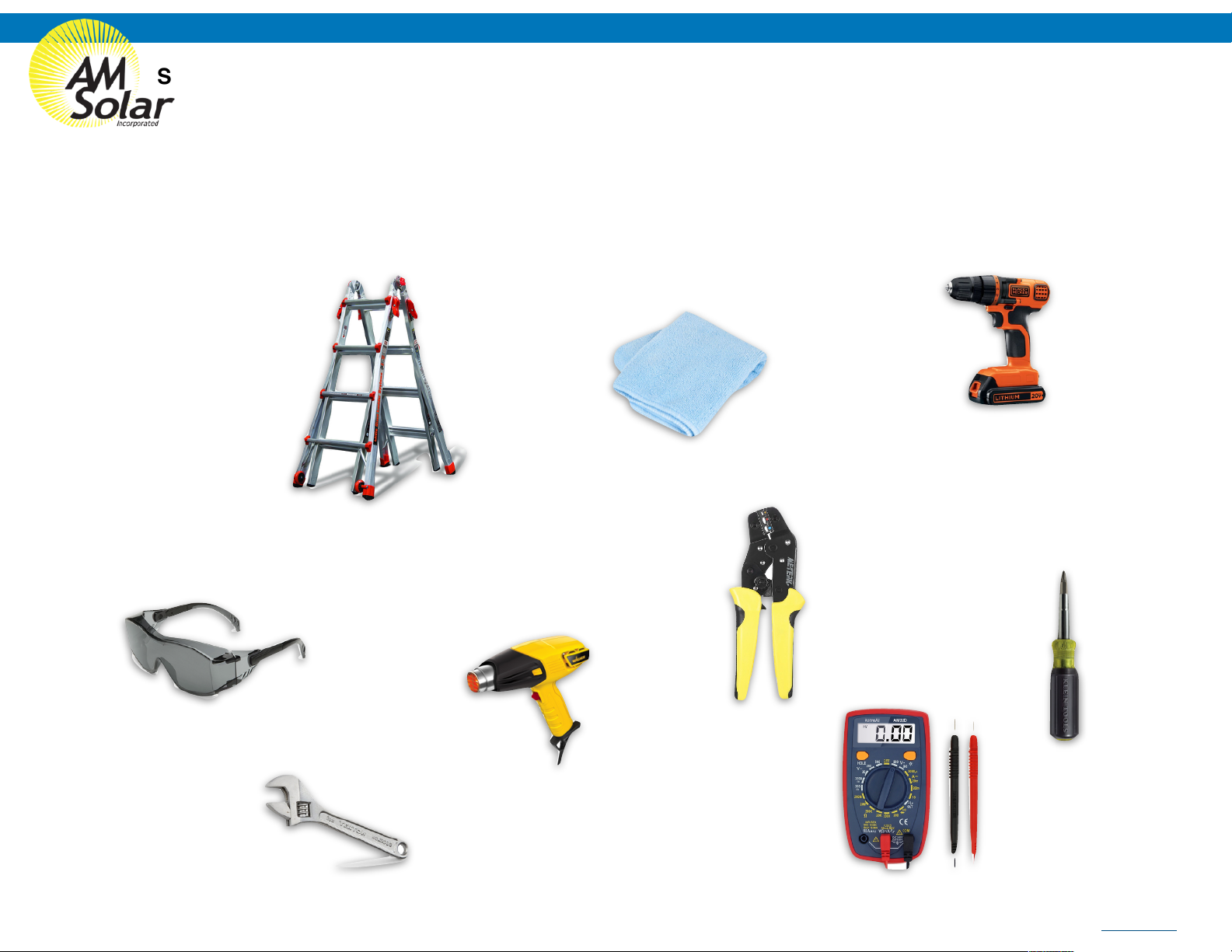
you many different installation options. Grab some chalk, cardboard, rope and a ball of string - We’re going to make some component placement templates.
Use chalk to outline spots for smaller items such as breakers and the fuse panel. Use the string to make the small wire runs, rope for heavy gauge, and label
them (tape and stickers works well). Then layout the all the components that fit the interior of your rig to prepare for installation.!
Keep it organized!
Stay organized by making your work tidy and well planned. Read the included product guides / instructions and ABC (Always Be Checking). If you
are installing and find that something was missed during your layout and planning and can't be installed correctly or safely, don't worry! Just
backtrack to that stage in your layout design, and find an alternative placement before moving forward.
!
Making it last!
No matter how long you plan on keeping this kit, it’s only going to be useful and have value if it's in good order. This equipment doesn’t react well to
neglect or abuse. When planning and performing the installation, use proper technique and plan for the long run. Using duck tape to secure a part in
place might be a good emergency fix, but you’ll want to start as “clean” as possible from the beginning.#
Component Proximity!
Always keep high current lines as short as possible. The battery to inverter cable should be under 10 feet, 5 feet would be ideal. If you are mounting all the
equipment in a very small area, be aware of the distance between all "connection points" - If a component comes loose and shifts for any reason, you will want
to ensure it will not result in components touching each other and possibly causing a short.#
General Guidelines and Tips
99-VANGLD Deep In The Woods
AM Solar Inc.!
3555 Marcola Rd.!
Springfield, OR 97477!
541.726.1091!
www.amsolar.com
Rev.20190923

Suggested Tools For Installation
Here is a list of some of the tools that might be needed for your installation.$If you feel this list is too ambiguous or potentially
intimidating, now would be a great time to schedule your installation work with the professionals at AM Solar.#
•Sturdy Ladder#
•Hammer Crimper#
•Hammer#
•Heat Gun#
•Wire Crimper#
•Wire stripper#
•Cable Cutter#
•Multimeter#
•Screwdriver#
•Smartphone#
•Drill#
•Box knife#
•91% Isopropyl Alcohol#
•Cleaning rags#
•Crescent wrench#
•Safety glasses
99-VANGLD Deep In The Woods
AM Solar Inc.!
3555 Marcola Rd.!
Springfield, OR 97477!
541.726.1091!
www.amsolar.com
Rev.20190923

Battery Bank
99-VANGLD Deep In The Woods Lithium Battery System
AM Solar Inc.!
3555 Marcola Rd.!
Springfield, OR 97477!
541.726.1091!
www.amsolar.com
The battery bank is the heart of the system.$Its components usually take up the most space and all other subsystems connect to it.$That’s
why we recommend installing it first.$This battery bank consists of a 200Ah Lithium Battery.$The Bluetooth battery monitor reads all
charging and discharging current through a shunt$and is able to interpret that data to compute battery usage, remaining energy, percent
charge, etc.$When a shunt is used, the load side of the shunt becomes the new negative battery terminal and no negatives will connect to
the actual battery.
AMS Li Control !
Module !
BATTBMS-AMSLB43
Boost connection
Solar
Solar Charger +
DC Loads +
VE.Bus BMS!
BATTBMS-VT-BUS
Inverter/charger AC input neutral
Inverter/charger AC input hot
Victron Inverter
Not Used - Cut
and Cap Wire
To Engine Battery
DC Loads
Mains Detector!
BATTBMS-VT-BUS
CABLE-VT-RJ45-3
CABLE-2GA-1-RED
CABLE-4/0-1-BLK
CABLE-18GA-2-GRY
LUG-4/0-RING-3/8
FSTSCW-612
FSTSCW-1058SS
CABLE-18GA-2-GRY
HS-RED-HD-1/2
HS-BLK-DWALL-3/16
15A Fuse!
93F-ATC-015A
15A
ALL POSITIVES +
93H-R3/4
LUG-2GA-RING-3/8
NOTE: Remove black
factory jumpers from
Battery Protect (BP100)
ALL NEGATIVES -
CABLE-2GA-1-RED
!
LUG-18GA-RING-BR
93H-B3/4
FSTSCW-1058SS
To Inverter T Sense
To Smart Battery Combiner
(Alternator Charging)
NOTE: Remove black
factory jumpers from
Battery Protect (BP100)
Victron Smart Lithium
Battery
MONITOR-VTBMV-S
(MONITOR)
MONITOR-VTBMV-S (SHUNT)
TEMP-BS
CABLE-VT-M8-1
CABLE-4/0-1-BLK
CABLE-4/0-1-BLK
LUG-4/0-RING-3/8
93H-B3/4
93H-B3/4
BATTLI-VT-200S
LUG-4/0-RING-3/8
- +
93H-B3/4
93H-R3/4
200Ah
Master Switch!
93S-MINI
93H-R3/4
93H-R3/4
FUSE
TEMP
CABLE-18GA-1-YLW
LUG-4/0-RING-3/8
LUG-4/0-RING-3/8
LUG-4/0-RING-3/8
+
-
-
-
+
+
-
+
FSTSCW-101SS
FSTSCW-101SS
BP100!
RELAY-VTSMBP100
LUG-2GA-RING-3/8
BP100!
RELAY-VTSMBP100
2ga!
Cable
4/0!
Cable
4/0!
Cable
Temp Sense
Cable
Positive
Terminal Post!
93P-RED
Negative
Terminal Post!
93P-BLK
4/0!
Cable
18ga!
Cable
18ga!
Cable
RJ45
Cable
RJ45
Cable
Victron
M8 Cable
2ga!
Cable
HS-RED-HD-1/2
LUG-2GA-RING-3/8
18ga!
Cable
18ga!
Cable
Rev.20190923

99-VANGLD Deep In The Woods Solar
Solar wire
penetrates roof
here
40
Amp!"
DC
Breaker
NOTICE:
The "greyed out"
battery bank
items are not
included, but you
will be
interacting with
them.
Back of Solar Panel(s) with Rocker Foot Mounts
Fuse
SOLAR-ZS100
CCTLR-VT-MPPS-030A
CABLE-6GA-2-GRY
91M-ZBZ
92S-MINI
92C-INTR
SEAL-SKF
+
SEAL-SKF
SEAL-SKF
SEAL-SKF
92C-INTR
SEAL-SKF
Back of Solar Panel(s) with Rocker Foot Mounts
Fuse
SOLAR-ZS100
91M-ZBZ
SEAL-SKF
+
SEAL-SKF
SEAL-SKF
SEAL-SKF
92C-INTR
93C-ZCBNR
CABLE-6GA-2-GRY
93B-040A
20-ROOF
Roof Combiner Box
93C-ZCBNR
93T-POS-6GA
93T-NEG-6GA
AM Solar Inc.!
3555 Marcola Rd.!
Springfield, OR 97477!
541.726.1091!
www.amsolar.com
ROOF COMBINER BOX
INSTALLATION VIDEO
ROCKER FOOT MOUNT
INSTALLATION VIDEO
SOLAR PANEL
INSTALLATION VIDEO
CABLE OUTPUT
INSTALLATION VIDEO
1
2
3
4
If the connections seem
tight on the MPPT, that is
normal. Scan here for
assistance.
5
Solar
-
-
Zamp 100W Solar Panel!
Mounted Dimensions:""42.7""x 19.8" x 1.38"
Zamp 100W Solar Panel!
Mounted Dimensions:""42.7""x 19.8" x 1.38"
CAUTION:
Be careful to avoid the negative wires from having any contact
with each other when plugged into the charge controller. The
ports are close together, and there can't be copper wires
crossing them outside of the controller.
6ga!
Cable
6ga!
Cable
6ga!
Cable
Solar On/Off
Switch
93C-ZCBNR
Rev.20190923

30 Amp
shore power
inlet
30
15
20
15
15
15
30
CABLE-10GA-3-GRY
CABLE-10GA-3-GRY
CABLE-10GA-3-GRY
Sub Panel
MAIN AC Panel
!
120 vAC!
receptacle
Inverter Remote
Inverter / Charger!
Master Disconnect
IMPORTANT NOTICE:
ALL the "greyed out" items are not included. You
will need to interact with them.
CAUTION:
Household alternating
electricity (AC) is
dangerous.
Use care and common
sense.
99-VANGLD Deep In The Woods AC Input / Output
95F-CLST-300A
93S-MINI
INV-VT-!
2000
MONITOR-VTDM
FUSE-CLST-300A
93H-R3/4
93H-R3/4
93H-R3/4
CORD-30A-25-L
OUTLET-30A-B
BOX-SPBS
SPLICE-12-CEC
CABLE-VT-RJ45-5
BRKR-AC-BRKR-15/15
BRKR-AC-BRKR-15/20
BRKR-AC-BRKR-30/15
STRN-S-3/4
STRN-!
S-3/4
BOX-MSB
STRN-S-11/4
93H-R3/4
93H-B3/4
BRKR-AC-DIN277V/30A
SPLICE-12-CEC
CABLE-14GA-2-WHT
LUG-2/0-
RING-3/8
LUG-2/0-RING-3/8
CABLE-2/0-1-BLK
CABLE-2/0-1-BLK
AC Input & Output
The AC Input/Output system is capable of plugging into a standard 30A shore power outlet.$(Note:
Adapters from 30A to 15A outlets can be purchased at hardware or RV supply stores).$The shore
power charges the battery bank and can also be passed through the inverter to the AC loads.$If the
loads draw more current than the shore power connection can provide, the inverter can meet the
demand up to the rating of the inverter by simultaneously drawing from the battery bank.$When not
plugged into shore power, the inverter will draw from the battery bank to power the AC loads.$When
not in use, save energy by turning offthe inverter via Digital Multicontrol included in the kit.
Zip tie the spare fuse nearby
so you can find it quickly.
LUG-2/0-RING-3/8
LUG-2/0-RING-3/8
LUG-2/0-RING-3/8
LUG-2/0-RING-3/8
CABLE-2/0-1-BLK
93H-R3/4
93H-B3/4
WIRETIE-05
OUTLET-15125
AM Solar Inc.!
3555 Marcola Rd.!
Springfield, OR 97477!
541.726.1091!
www.amsolar.com
2/0 Cable
2/0 Cable
Rev.20190923
Temp Sense
Mains Detector
Purple
Mains Detector !
Blue

USB & 12 v.d.c.
"" """""outlets
1.$$$$ Position the components so cable routes can be
planned.$#
2.$$$$ Install the negative cable from the negative
terminal to the negative post of the DC fuse block.#
3.$$$$ Connect the positive cable from the positive side
of the DC fuse block to the LOAD post of the breaker.$
Turn the breaker to the OFF position.#
4. Connect the positive cable from the LINE side of
the breaker to the Battery Protect#
4.$$$$ Install the outlet and connect it to the fuse block.$
A parallel connection between the two sets of outlet
posts will have to be made by fitting two sets of cable
into a positive and a negative female spade lug.#
5.$$$$ Verify the connections to make sure that they are
correct and tight.#
6. Activate the system by turning the DC breaker to
ON.$If the DC loads do not work, toggle the DC load
master switch.
CAUTION:
Before “going live” with the DC power,
check and double check all connections
and fittings. Look for looseness, routing
issues and polarity (+=+, etc.)
99-VANGLD Deep In The Woods DC Distribution
FUSEHLDR-MULT
LUG-6GA-RING-1/4
LUG-10GA-FAST-F
CABLE-6GA-2-GRY
BRKR-DC-BRKR-060A
One DC outlet with dual USB and standard 12V is included.$Additional outlets can be connected to the fuse block or wired in parallel to the
existing outlet.
OUTLET-12USB
HS-RED-DWALL-1/2
LUG-6GA-!
RING-3/8
CABLE-10GA-2-WHT
HS-BLK-DWALL-1/2
FSTSCW-834B
DC Distribution
60
Amp!"
DC
Breaker
LUG-6GA-RING-3/8
LUG-6GA-RING-3/8
LUG-6GA-RING-3/8
FSTSCW-834B
HS-RED-DWALL-1/2
HS-BLK-DWALL-1/2
+
HS-RED-DWALL-1/2
HS-RED-
DWALL-1/2
AM Solar Inc.!
3555 Marcola Rd.!
Springfield, OR 97477!
541.726.1091!
www.amsolar.com
6ga Cable
6ga Cable
10ga 2-strand
Rev.20190923

99-VANGLD Deep In The Woods Alternator Charging
Rev20190410
FSTSCW-612
PLATE-MOM
SWITCH-ESSCLD
MOMENTARY
starter BOOST
Flooded 12VDC
ENGINE BATTERY
LUG-2/0-RING-3/8
93H-R3/4
CABLE-2/0-1-BLK
93H-R3/4
CABLE-18GA-2-GRY
IMPORTANT NOTICE:
All the "greyed out"
items are not included.
You will need to interact
with them.
CABLE-18GA-2-GRY
2/0 Cable
18/2 Cable
LUG-18GA-RING-BR
To Boost Switch
93H-R3/4
93H-R3/4
LUG-2/0-RING-3/8
LUG-2/0-RING-3/8
LUG-2/0-RING-3/8
LUG-2/0-RING-3/8
LUG-2/0-RING-3/8
LUG-2/0-RING-3/8
93H-R3/4
93H-R3/4
93H-B3/4
93H-B3/4
93B-200A
200
Amp!$#
DC
Breaker
LUG-2/0-RING-3/8
93H-R3/4
AM Solar Inc.!
3555 Marcola Rd.!
Springfield, OR 97477!
541.726.1091!
www.amsolar.com
RELAY-VTCY
18ga wire
2/0 Cable
Chassis
Ground
18ga wire
To Boost Switch

Programming / Commissioning Your System - The BMV-712 Smart Battery Monitor
Programming the Battery Monitor
Programming on the BMV-712 Battery Monitor:
1. Download “Victron Connect” from the Google Play Store (picture 1).#
2. Turn on your Phone’s Bluetooth, and get as close as possible to your Victron
Component(s).#
3. Open the Victron Connect app, and after it takes a moment to scan it will
recognize your BMV-712.#
NOTE: If your device is not shown, it is probably signal interference. Try
closing the app and moving to a different location before re-entering the app in a
location that can pick up the BMV signal.#
4. Select the BMV-712 on the Device List (picture 2).#
5. Typ e 000000 to login for the first time.#
6. Press the gear icon in the top right corner (picture 3).#
7. Enter “Battery Settings” and change the values below (similar to picture 4):#
8. Changing Battery Capacity: Enter the number of Ah of your entire battery bank#
9. Charge Voltage: 13.9#
10. Tai l Cu rre nt : 2%#
11. Peukert Exponent: 1.1#
12. Charge Efficiency Factor: 98%#
13. Tem pe ra tu re Un it : “FAHR” Fahrenheit#
14. Aux Input: User Option (“Temp”)#
15. Exit from the device.#
NOTE: Only one phone can be connected to !
each device at a time. Be sure to completely !
disconnect and close the app to log out!
from the device.
Program Settings for Lithium Batteries
•Battery Capacity: Enter the total battery capacity in Amp Hours.#
•Charge Voltage: 13.9#
•Tail C u r re n t: 2%#
•Peukert Exponent: 1.1#
•Charge Efficiency Factor: 98%#
•Temp e r ature Un i t : “CELC” (Celsius) or “FAHR” Fahrenheit#
•Aux Input: User Option (“Temp” works best)
!
We recommend you interface with the BMV-712 through the Victron app on your phone, and
change the settings from there. The app is named “VictronConnect”. Ensure your Bluetooth
is enabled before entering the app. Once inside the app you will see your BMV-712
displayed, click on it to change the applicable settings:
NOTE: To change the PIN code from the app, go back to the device list page in the app.
Click on the three circles to the right of your device, and select “Reset PIN code”.
1
2
3
4
AM Solar Inc.!
3555 Marcola Rd.!
Springfield, OR 97477!
541.726.1091!
www.amsolar.com
Rev.20190923

Programming: The MPPT Charge Controller for Lifeblue Lithium Batteries
Programming / Commissioning Your System - The Charge Controller
Charge Control Settings for LifeBlue
Lithium Batteries:
1. Download the “VictronConnect” App to your phone.#
2. Open the App.#
3. You ’l l se e a se le ct io n fo r yo ur S ma rt So la r MP PT C ha rge r,
select it.#
4. Typ e 000000 to login for the first time.!
NOTE: To change the PIN code, go back one step to the
main screen. Click on the 3 buttons to the right of the
controller image, and select “Reset PIN Code”.#
5. Click on the gear in the top right corner.#
6. Click on “Battery”.#
7. Click on the settings and adjust them accordingly to match
below:!
!
- Battery voltage: 12V!
- Max charge current: 30A (In this example)!
- Use default charge settings: OFF!
- Charger enabled: ON!
- Battery Preset: User defined!
- Expert Mode: ON!
- Absorption voltage: 14.40 V!
- Float voltage: 13.80 V!
- Equalization voltage: 13.80 V!
- Absorption Duration: Fixed!
- Absorption Time: 00:20 (20 minutes)!
- Auto Equalization: Disabled (Off)!
- Temperature compensation: Disabled (Off)
13.80V
14.40V
Device List within
VictronConnect
MPPT Charge Controller
Screen
15 Minutes
Lifeblue
AM Solar Inc.!
3555 Marcola Rd.!
Springfield, OR 97477!
541.726.1091!
www.amsolar.com
Rev.20190923
Battery Settings Screen

Programming: Linking the BMV and Charge Controller on Smart Network
Creating The Network
1. When in the Victron Connect App, click on one of your devices.#
2. Go to “Settings” (shown as a gear symbol in the top right, picture 1).#
3. Go to “VE.Smart networking” (picture 2).#
4. Go to “Create Network” (picture 3).#
5. Enter a name for your network (picture 4).#
Linking Each Device:
1. Enter the Victron Connect App and click on a device.#
2. Go to “Settings” (shown as a gear symbol in the top right, picture 1).#
3. Go to “VE.Smart networking” (picture 2)#
4. Go to “Join Existing Network” (picture 3)#
5. Select the network you just created (picture 5).#
6. This device is now joined to the network (picture 7). Repeat this step for every other bluetooth enabled device.
1
2
3
4
5
7
Rev.20190923

Programming: BP Battery Protection
Rev.20190923
Programming / Commissioning Your System - The Smart BP-100 Battery Protection
1. Supply 12V power to the BP (+ to IN post, - to GND pin).#
2. Open VictronConnect and select the Battery Protect.#
3. The first screen has a switch to manually toggle the relay.#
4. Click the gear in the top right to enter Settings.#
5. Select “user defined” from the Preset menu.#
6. Enter the following values:#
Shut down: 10.8v#
Restart: 11.9v#
7. Mode: Leave on “B”#
8. Alarm output: Select ”Relay” from the menu.
2. Select BatteryProtect from VictronConnect
5. Select “User defined” from the Preset
menu
7. Mode should be set to “Relay mode”
8. Alarm output: Select “Relay”
4. Select the gear icon
AM Solar Inc.!
3555 Marcola Rd.!
Springfield, OR 97477!
541.726.1091!
www.amsolar.com
NOTE: These setting were chosen on the conservative side, but can be adjusted depending on your needs. Do not lower the shut down voltage until you are
very familiar with your system, since dropping below 12v may result in battery degradation.!
!
If your battery protect shuts down your loads, it’s important you recharge your batteries up to a full charge as soon as possible.
To Ground
To Battery
To Breaker
BP100 Detail
NOTE: Remove black
factory jumper from
Battery Protect (BP100).

Updating Your Victron Color Control Display (Page 1/2)
Programming Your Victron Color Monitor
These devices connect via
Bluetooth to communicate
with a smartphone using the
VictronConnect app.
Connecting Your Victron Display to Wireless:
1. Press the top right button on the display (menu), and use the down directional button to scroll to Settings.
Enter the Settings screen by pressing the center button when “Settings” is highlighted.#
2. Use the down directional button to scroll to “Wifi” (near the bottom of the list). Press the center button when
highlighted to enter Wifi.#
3. Highlight the network you are connecting to, using the up and down directional buttons to scroll if needed.
Press the center button to connect once the wireless network is highlighted.#
&Ifapasswordisrequired,itwillpromptyouhere.Usetheupanddowndirectionalbuttonstoselect
letters. Press the right directional button to move to the next letter. Press the center button when the full password
is entered.#
4. The connection could take up to 1 minute to complete. Ensure it displays “connected” when done. You now
have internet access to your display. Be sure to remain within the wireless signal range during the duration of
the firmware upgrade in the next step.!
Updating The Display Firmware:
1. Use the left direction button to go back to the “Settings” screen. #
2. Use the down directional button to scroll to “Firmware” (2nd down from the top), and press the center button
once highlighted.#
3. Select “Online updates”. Press the center. Button once highlighted.#
4. Select “Check for Updates”. It will proceed with checking for updates.#
5. Select “Perform Updates”. It can take up to 5 minutes for the updates to be applied and the system to reboot.#
6. It should now display a message stating it’s on the latest version in the “Firmware” section.#
Helpful Notes:
•Pressing the center button will always select what is highlighted.#
•Pressing the left arrow will take you back to the previous screen.#
•Pressing the top right button will pull up the Settings page.
Bottom Directional Button
Top Directional Button
AM Solar Inc.!
3555 Marcola Rd.!
Springfield, OR 97477!
541.726.1091!
www.amsolar.com
Rev.20190828

Recording the VRM Portal ID:#
1. Go back to Settings, then enter “VRM Online Portal”.#
2. Tak e a ph ot og ra ph o f th e VR M on li ne p or ta l ID f or f ut ure re fe ren ce .#
!
Changing Settings:#
3. Go to settings by pressing the top right button, then enter “Remote Console”.#
4. Click on “Disable password check”. It will give you a notice that “Password check has been disabled”.#
5. Turn “Enable on VRM” to on.#
1. Ensure you select “No Password Required”#
6. Go back to settings, then enter Date and Time and set date/time.#
7. Go back to settings, enter “General” then select “reboot?”.#
8. Enter settings once rebooted, then enter Services and turn on VRM two-way communication.
9. Go to Settings, then enter “System Setup”.#
•Change all settings to the following:#
•AC Input 1: Shore Power#
•AC Input 2: Generator#
•Battery Monitor: Automatic#
•Has DC System: On
Updating Your Victron Color Control Display (Page 2/2)
AM Solar Inc.!
3555 Marcola Rd.!
Springfield, OR 97477!
541.726.1091!
www.amsolar.com
Rev.20190828

Using the Victron VRM Portal
Getting your VRM Portal ID
1. Press the menu button on your Color Control.#
2. Go to “Settings”.#
3. Go to “VRM Online Portal”.#
4. Take a p h o togr a p h or wr i t e d own y o u r VRM po r t al ID sh o w n here. It w i l l be use d f o r lat e r p urpo s e s.#
Generating A Login:
1. Go to vrm.victronenergy.com from a computer or tablet.#
2. Click on the “Register For Free” button.#
3. Complete all the fields with your name, etc. except “Company”. Enter AM Solar for the field “Victron Dealer”. #
4. Click “Register”.#
5. Upon registration, you will get an email sent to the address you entered. The email includes a link to verify your
account, click on the link in the email.#
6. Once clicking the link in your email to confirm your account, you are now registered. Your browser window
should automatically log you into the VRM portal. If it doesn’t automatically log you in, you can visit
vrm.victronenergy.com and enter your login credentials.#
Adding Your Color Control To Your Portal Account:
1. Click on “Add Installation” in the top left menu.#
2. Click on the picture of the Color Control GX.#
3. Scroll down to the bottom of the screen, you’ll see a box where you can enter your VRM Portal ID#
4. Enter your VRM Portal ID here that you obtained from your Color Control Settings.#
5. The device is now always viewable under “Installations” in the top right menu when you login.#
AM Solar Inc.!
3555 Marcola Rd.!
Springfield, OR 97477!
541.726.1091!
www.amsolar.com
VRM Screenshots:
Rev.20190923

Troubleshooting The System
Troubleshooting Steps
Rev.201909019
Steps to take before calling AM Solar:
1. Get a voltmeter and test the voltage of the batteries directly to ensure they aren’t drained.#
&-Ifyouaren’tfamiliarwithhowtooperateyourvoltmeter,testitonaknownpower
source like your car starter battery to ensure you are reading it correctly.#
2. If your problem is related to solar:!
- Perform a system reset on the solar side. First disconnect the panels from the
controller, usually done with an on/off switch. Then disconnect the battery from the
controller. After 10 seconds, reconnect the battery to the controller and give it 15 seconds
to boot up. Then reconnect solar.!
- Download the latest version of the VictronConnect App to your device, and attempt
to reconnect#
3. If you problems is related to the inverter:!
- Power cycle the inverter by powering it off and back on.#
&-Checkthedisplay(s)toensureitisn’tremotelypoweredoff,orthecurrentlimitisset
too low to not allow enough power from shore.#
4. Check all connection points to ensure there are no loose connections.#
5. Check all on/off switches to ensure they are on, and all DC breakers are reset.#
6. Check all inline fuses to ensure they haven’t blown. You have the following fuses in this kit,
with a spare included for each:!
- Inverter 300Amp Class T Fuse!
- Victron BMS 15A fuse!
- Temperature Sensor Fuse#
7. Power cycling the entire system by turning the master electrical on/off switch to off, give it 5
seconds, and then back on.
AM Solar Inc.!
3555 Marcola Rd.!
Springfield, OR 97477!
541.726.1091!
www.amsolar.com
If you are still having issues with your system, call AM Solar at 541-726-1091 to be put into our troubleshooting
queue. Give us a shout before you get a headache and we’ll help you through things! Please have a volt meter
handy and performed the applicable tests above before contacting us. We’ll be glad to help get you back up
and running as quickly as possible!

Solar
DC Loads
15A
ALL POSITIVES +
ALL NEGATIVES -
Lithium Battery
- +
FUSE
TEMP
-
+
Table of contents
Other AM Solar Inverter manuals
Popular Inverter manuals by other brands

ANLU
ANLU AG-HA-3000N owner's manual

Champion
Champion 100814 Operator's manual

Helios
Helios RM-PSW5KVA Series instruction manual

Mastervolt
Mastervolt Mass Combi 12/1200-60 user manual

Chicago Electric
Chicago Electric Power Systems 97047 Set up and operating instructions

Puredrive
Puredrive Hybrid Series Installer's guide