Amano American Sanders American 8 User manual

Drum Sander
American 8
Operator’s Manual


1
Contents
Operator Safety Instructions................................................... 1-4
Machine Specifications...............................................................5
230V Electrical Schematic..........................................................6
Machine Transportation..............................................................6
Machine Setup ....................................................................... 7-8
Chatter-Wave Prevention ...........................................................8
Machine Operation ............................................................... 9-10
Sander Adjustments ............................................................11-12
Routine Maintenance ...............................................................13
Troubleshooting........................................................................14
Wiring Diagram.........................................................................17
Handle Assy ....................................................................... 18-19
Base Assy - 1 ..................................................................... 20-21
Base Assy - 2 ..................................................................... 22-23
Accessories ..............................................................................23
Warranty ...................................................................................24
READ THIS BOOK
This book has important information for the use and safe operation of this machine. Failure to read this book prior to
operating or attempting any service or maintenance procedure to your American Sanders machine could result in injury
to you or to other personnel; damage to the machine or to other property could occur as well. You must have training in
the operation of this machine before using it. If your operator(s) cannot read this manual, have it explained fully before
attempting to operate this machine.
All directions given in this book are as seen from the operator’s position at the rear of the machine.
***This product is intended for commercial use only***
In this Operation Manual you will find three statements that you must read and observe to ensure safe operation of this
machine.
DANGER means: Severe bodily injury or death can occur to you or other personnel if the DANGER
statements found on this machine or in this Operation Manual are ignored or are not adhered to. Read
and observe all DANGER statements found in this Operation Manual and on your machine.
WARNING means: Injury can occur to you or to other personnel if the WARNING statements found on
your machine or in the Operation Manual are ignored or are not adhered to. Read and observe all
WARNING statements found in this Operation Manual and on your machine.
CAUTION means: Damage can occur to the machine or to other property if the CAUTION statments found
on your machine or in this Operation Manual are ignored or are not adhered to. Read and observe all
CAUTION statments found in this Operation Manual and on your machine.
Operator Safety Instructions
WARNING!
The Products sold with this Manual contain or may contain chemicals that are known to certain governments (such as the State of
certain locations (including the State of California) purchasers of these Products that place them in service at an employment job site
or a publicly accessible space are required by regulation to make certain notices, warnings or disclosures regarding the chemicals that
are or may be contained in the Products at or about such work sites. It is the purchaser’s responsibility to know the content of, and
to comply with, any laws and regulations relating to the use of these Products in such environments. The Manufacturer disclaims any

2
Failure to read the Owner’s Manual prior to operating or servicing your American Sanders machine could result in injury to
you or to other personnel; damage to the machine or to other property could occur as well. You must have training in the
operation of this machine before using it. If you or your operator(s) cannot read English, have this manual explained fully
before attempting to operate this machine.
A. Sanding/nishing wood oors can create an explosive or combustible environment. Do not operate this machine around
solvents, thinners, alcohol, fuels, oor nishes, wood dust or any other ammable materials. Cigarette lighters, pilot lights,
electrical sparks and all other sources of ignition should be extinguished or avoided. Keep work area well ventilated.
B. Dust generated from sanding wood oors can spontaneously ignite or explode. Promptly dispose of any sanding dust in
a metal container clear of any combustibles. Do not dispose in a re.
A. Electrocution could occur if the machine is being serviced while the machine is connected to a power source. Disconnect
the power supply before servicing.
B. Electrocution or re could occur if the machine is being operated with a damaged power cord. Keep the power cord clear
of the pad. Always lift the cord over the machine. Do not move the machine by the power cord.
C.Shock hazard. Do not use the machine if it has been rained on or sprayed with water.
To avoid injury keep hands, feet, and loose clothing away from all moving parts on the machine. Disconnect the power cord
before replacing the pad, changing the abrasive, or when servicing. Do not operate the machine unless all guards are in
place. Never leave the machine unattended while connected to a power source.
Injury can occur if protective clothing or equipment is not used while sanding. Always wear safety goggles, protective
clothing, and dust mask while sanding.
This sander is not to be used on pressure treated wood. Some pressure treated woods contain arsenic and sanding
pressure treated wood produces hazardous dust. Inhaling hazardous dust from pressure treated wood can cause serious
injury or death. Sanding pressure treated wood decks or uneven surfaces can damage the sander which is not covered
under warranty or damage waiver.
Any alterations or modications of this machine could result in damage to the machine or injury to the operator or other
bystanders. Alterations or modications not authorized by the manufacturer voids any and all warranties and liabilities.
Risk of explosion. Floor sanding can result in an explosive mixture of ne dust and air. Use oor sanding machine only in a
well-ventilated area free from any ame or match.
DANGER:
DANGER:
DANGER:
DANGER:
WARNING:
WARNING:
WARNING:
WARNING:
WARNING: Read all safety warnings and instructions. Failure to follow warnings and instructions may result in electric
shock, re and or serious injury.
Save all warnings and instructions for future use.
The term “power tool” in the warnings refers to your main-operated (corded) power tool or battery operated (cordless) power tool.
1) Work area safety
a) Keep work area clean and well lit. Clutter or dark areas invite accidents.
b) Do not operate power tools in explosive atmospheres, such as in the presence of ammable liquids, gasses, or dust.
Power tools create sparks which may ignite the dust or fumes.
c) Keep children and bystanders away while operating a power tool. Distractions can cause you to lose control.
2) Electrical safety
a) Power tool plugs must match the outlet. Never modify the plug in any way. Do not use any adapter plugs with
earthed (grounded) power tools. Unmodied plugs and matching outlets will reduce risk of electric shock.
b) Avoid body contact with earthed or grounded surfaces such as pipes, radiators, ranges, and refrigerators. There is an
increased risk of electric shock if your body is earthed or grounded.
c) Do not expose power tools to rain or wet conditions. Water entering a power tool will increase the risk of electric shock.
d) Do not abuse the cord. Never use the cord for carrying, pulling or unplugging the power tool. Keep cord away from
heat, oil, sharp edges or moving parts. Damaged or entangled cords increase the risk of electric shock.
e) When operating a power tool outdoors, use an extension cord suitable for outdoor use. Use of cord suitable for outdoor
use reduces the risk of electric shock.
General Power Tool Safety Warnings

3
Failure to read the Owner’s Manual prior to operating or servicing your American Sanders machine could result in injury to
you or to other personnel; damage to the machine or to other property could occur as well. You must have training in the
operation of this machine before using it. If you or your operator(s) cannot read English, have this manual explained fully
before attempting to operate this machine.
A. Sanding/nishing wood oors can create an explosive or combustible environment. Do not operate this machine around
solvents, thinners, alcohol, fuels, oor nishes, wood dust or any other ammable materials. Cigarette lighters, pilot lights,
electrical sparks and all other sources of ignition should be extinguished or avoided. Keep work area well ventilated.
B. Dust generated from sanding wood oors can spontaneously ignite or explode. Promptly dispose of any sanding dust in
a metal container clear of any combustibles. Do not dispose in a re.
A. Electrocution could occur if the machine is being serviced while the machine is connected to a power source. Disconnect
the power supply before servicing.
B. Electrocution or re could occur if the machine is being operated with a damaged power cord. Keep the power cord clear
of the pad. Always lift the cord over the machine. Do not move the machine by the power cord.
C.Shock hazard. Do not use the machine if it has been rained on or sprayed with water.
To avoid injury keep hands, feet, and loose clothing away from all moving parts on the machine. Disconnect the power cord
before replacing the pad, changing the abrasive, or when servicing. Do not operate the machine unless all guards are in
place. Never leave the machine unattended while connected to a power source.
Injury can occur if protective clothing or equipment is not used while sanding. Always wear safety goggles, protective
clothing, and dust mask while sanding.
This sander is not to be used on pressure treated wood. Some pressure treated woods contain arsenic and sanding
pressure treated wood produces hazardous dust. Inhaling hazardous dust from pressure treated wood can cause serious
injury or death. Sanding pressure treated wood decks or uneven surfaces can damage the sander which is not covered
under warranty or damage waiver.
Any alterations or modications of this machine could result in damage to the machine or injury to the operator or other
bystanders. Alterations or modications not authorized by the manufacturer voids any and all warranties and liabilities.
Risk of explosion. Floor sanding can result in an explosive mixture of ne dust and air. Use oor sanding machine only in a
well-ventilated area free from any ame or match.
f) If operating a power tool in a damp location is unavoidable, use a residual current device (RCD) or ground fault circuit
interrupter (GFCI) protected supply. Use of a RCD or GFCI reduces the risk of electric shock.
3) Personal safety
a) Stay alert, watch what you are doing and use common sense when operating a power tool. Do not use a power tool
while you are tired or under the inuence of drugs, alcohol, or medication. A moment of inattention while operating
power tools may result in serious personal injury.
b) Use personal protective equipment. Always wear eye protection. Protective equipment such as dust mask, non-skid
safety shoes, hard hat, or hearing protection used for appropriate conditions will reduce personal injury.
c) Prevent unintentional starting. Ensure switch is in o-position before connecting to power source and/or battery
pack, picking up, or carrying the tool.
have the switch on invites accidents .
d) Remove any adjustment wrench or key before turning the power tool on. A wrench or key left attached to a rotating part
of the power tool may result in personal injury.
e) Do not overreach. Keep proper footing and balance at all times. This enables better control of the power tool in
unexpected situations .
f) Dress properly. Do not wear loose clothing or jewelry. Keep your hair, clothing and gloves away from moving parts.
g) If devices are provided for the connection of dust extraction and collection facilities, ensure these are connected and
properly used.
via a residual current device with a rated residual current of 30mA or less.
4) Power tool use and care
a) Do not force the power tool. Use the correct power tool for your application. The correct power tool will do the job better
and safer at the rate for which it was designed .
b) Do not use the power tool if the switch does not turn it on and o. Any power tool that cannot be controlled with the
switch is dangerous and must be repaired .
c) Disconnect the plug from the power source and/or the battery pack from the power tool before making any
adjustments, changing accessories or storing power tools. Such preventative safety measures reduce the risk of starting
the power tool accidently.
d) Store idle power tools out of the reach of children and do not allow persons unfamiliar with the power tool or these
instructions to operate the power tool. Power tools are dangerous in the hands of untrained users.
e) Maintain power tools. Check for misalignment or binding of moving parts, breakage of parts and any other condition
that may aect the power tool's operation. If damaged, have the power tool repaired before use. Many accidents are
caused by poorly maintained power tools .
f) Keep cutting tools sharp and clean. Properly maintained cutting tools with sharp cutting edges are less likely to bind and
are easier to control.
g) Use the power tool, accessories and tool bits ect. in accordance with these instructions , taking into account the
working conditions and the work to be performed.
5) Service
a) Have the power tool serviced by a qualied repair person using only identical replacement parts. This will ensure that
the safety of the power tool is maintained . If the supply cord is damaged, it must be replaced by the manufacturer , its service
Safety Warnings For Sanding Operations
accessory can be attached to your power tool, it does not assure safe operation .
4. The rated speed of the accessory must be at least equal to the maximum speed marked on the power tool. Accessories
accessories cannot be adequately guard or controlled.
with arbor holes that do not match the mounting hardware of the power tool will run out of balance, vibrate excessively and
may cause loss of control.
7. Do not use damaged accessory. Before each use inspect the accessory such as abrasive wheel for chips or cracks, backing
pad for cracks , tear or excess wear, wire brush for loose or cracked wires . If power tool or accessory is dropped , inspect
for damage or install an undamaged accessory. After inspecting or installing an accessory, position yourself or bystanders
away from the plane of the rotating accessory and run the power tool at maximum no-load speed for one minute . Damaged
accessories will normally break apart during this time .

4
8. Wear personal protective equipment. Depending on application, use face shield, safety goggles or safety glasses. As
noise may cause hearing loss.
9. Keep bystanders a safe distance away from work area. Anyone entering the work area must wear personal protective
operation .
10. Hold power tool by gripping insulated surfaces (handle) only, when performing an operation where the cutting accessory may
contact hidden wiring or its own cord. Cutting accessory contacting a "live" wire may make exposed metal parts of the power
tool "live" and shock the operator.
11. Position the cord clear of the spinning accessory. If you loose control, the cord may be cut or snagged and your arm or hand
may be pulled into the spinning accessory.
12. Never lay the power tool down until the accessory has come to a complete stop. The spinning accessory may grab the
surface and pull the power tool out of your control.
13. Do not run the power tool while carrying it at your side. Accidental contact with the spinning accessory could snag your
clothing, pulling the accessory into your body.
14. Regularly clean the power tools air vents. The motor's fan will draw the dust inside the housing and excessive accumulation
disc or kickback.
Kickback and Related Warnings
Kickback is a sudden reaction to a pinched or snagged rotating wheel, backing pad, brush or any other accessory. Pinching or
snagging causes rapid stalling of the rotating backing pad which in turn causes uncontrolled power tool to be forced in the opposite
direction of the backing pad's rotation at the point of the binding.
For example, if an abrasive wheel is snagged or pinched by the work piece, the edge of the wheel that is entering into the pinch
point can dig into the surface of the material causing the wheel to climb out or kick out. The wheel may either jump toward or away
from the operator, depending on direction of the wheel's movement at the point of pinching. Abrasive wheels may also break under
these conditions.
Kickback is the result of power tool misuse and incorrect operating procedures or conditions and can be avoided by taking proper
precautions as given below.
auxiliary handles, if provided for maximum control over kickback or torque reactions during start up. The operator can control
torque reactions or kickback forces, if proper precautions are taken.
2. Never place your hand near the rotating accessory. Accessory may kickback over your hand.
3. Do not position your body in the area where power tool will move if kickback occurs. Kickback will propel the tool in the
direction opposite to the wheel's movement at the point of the snagging.
4. Use special care when working corners, sharp edges etc. Avoid bouncing and snagging the accessory. Corners, sharp edges
or bouncing have a tendency to snag the rotating accessory and cause loss of control or kickback.
Additional Rules For Safe Operation
1. Empty the dust bag or dust collection receiver frequently. Do not leave residue in dust bag or dust collection receiver
unattended . Always empty in a non-combustible metal container. Sanding wood or varnish produces dust that can self ignite
and cause injury or damage. Follow this precaution for storage.
2. Set all exposed nails. Sweep loose abrasive away from work area. Do not strike metal pipes, ect., with sanding paper.
Striking metal or abrasive particles with sanding paper produces sparks that could ignite the sanding dust which can cause
injury or damage.
tight. Operating a partially assembled power tool could result in injury to the operator or bystander and could cause damage to
the equipment or surroundings .
4. Do not attempt to change the sanding paper while the power tool is running. The sanding pad can snag clothing and cause
injury to limbs and moving sanding paper can cause abrasions.
5. The power tool should only be used on an electrical system (mains) that is rated for the electrical requirements of the power

5
Machine Specifications
Operating Controls
Motor Starter / Protector
Sanding Pressure
Adjustment
Leveling Controls
Tool Storage Tray
* revolutions per min. *surface feet per min. *meters per min * cubic feet per min.
**Steel (Standard) Urethane or canvas (optional) ***Urethane (Standard) Steel or Canvas (optional)
CAUTION Your equipment may be inappropriate
cannot support the pressure created by hard wheels. A felt
or rubber wheel should be used when these woods are
encountered. See parts list for optional wheels.
product. Determine suitability of your equipment in
preparing the product.
Model American 8
PART NUMBER 07032C 07105A 07048C 07106A
Abrasive Size 8 x 26½” paperback 20.3 x 67.3 cm
Contact Wheel Speed (rpm)* 2400/2800 2000/2333
Abrasive Speed (sfm)* (m/min)* 4398/5131 sfm 1117/1303 m/min.
Dust Fan Speed (rpm)* 6000 5000
Dust Fan Flow (cfm)* 210 cfm 83 liters/second
Motor 60 Hz 230V 4hp (3 kW) 50 Hz 240V 3hp (2.2 kW)
Leveling Control Externally Adjustable
Operating Control Adjustable Lever
Motor Starter/Protector Magnetic Circuit Breaker
Sanding Pressure Adjustment Innitely Circuit Breaker
Wheels (Truck Assembly) Steel ** Urethane*** Steel** Urethane***
Wheel (Rear) Steel Canvas Steel Canvas
Drive V-Belt
Dimensions 40½ x 15 x 36 103 cm x 38 cm x 93 cm
Weight 216 lbs. 98kg

6
230V Electrical Connection Instructions
Machine Transportation
CAUTION: This machine will operate only on AC frequency and on electrical voltage shown on the motor nameplate. Make
sure you have the correct frequency and voltage before connecting the power cord to an outlet. The machine has
a plug as shown below.
DANGER: Electrocution could occur if the machine is exposed to water or rain. Keep the machine in a dry building.
DANGER:
Electrocution could occur if machine is improperly connected to the electrical system. To prevent possible electric
shock
, always use a 3wire electrical system connected to an electrical ground. For maximum protection against
electrical shock, use a circuit that is protected by a ground fault circuit interrupter. Consult your electrical
contractor.
DANGER: Electrocution could occur if the ground pin is tampered with in any way. Do not cut, remove, or break the ground
pin. Do not try to t a three-terminal plug into a receptacle or connector body other than a three plug receptacle
or connector body. If the outlet does not t the plug, consult your electrical contractor.
DANGER: Electrocution could occur if the machine is used with a damaged plug or power cord. If the cords or plugs are worn
or damaged in any way, have them replaced by an authorized service person or electrician.
If motor appears to labor or takes a considerable longer time to come up to speed reduce sanding pressure.
This machine must be connected to an electrically ground circuit in order to pro-
tect the operator from electric shock. This machine has an approved power cord
with three conductors as well as a plug with three terminals. Connect the plug into
a three holed receptacle. For maximum protection against electric shock, use a
circuit that is protected by a ground fault circuit interrupter.
Extension Cords
Use only an approved three-pronged extension cord with two main conductors
and one earthing conductor. This machine is equipped
with a power cord. When greater range is needed follow the table
below to determine cable gauge of additional footage. Refer to the
chart to the right for extension cord information
To transport the machine, follow this procedure:
1. Make sure the power cable is disconnected from the electrical outlet.
2. Disconnect the handle plug connection. See gure 1.
3. Remove the belt cover.
4. Remove the fan belt.
5. Loosen the motor bolt. Using the ¾” wrench, turn the motor bolt counterclockwise.
6. Using the 9/16” wrench, remove the two hex nuts (1).
7. Lower the motor locating screws (2). To lower the motor locating screws, turn the screws
clockwise. Make sure the screws are aligned with the openings at the front of the motor
platform. See gure 2.
8. Slide the motor forward.
9. Remove the drive belt.
10. Remove the motor from the chassis.
To re-assemble the machine after transporting, follow this procedure:
1. Reposition motor on chassis.
2. Install the drum belt. Slide the motor back until adequate tension is achieved in belt.
3. Resecure the motor to the chassis.
4. Install the fan belt.
5. Install the belt cover.
6. Reconnect the handle plug.
Clarke®American Sanders American 8 Floor Sander Operator's Manual Page 7
How to Transport the Machine
WARNING: The machine is heavy. Remove the
motor from the machine before trans-
porting. Get help loading the machine
and motor.
To transport the machine, follow this procedure:
1. Make sure the power cable is disconnected from the
electrical outlet.
2. Disconnect the handle plug connection. See gure 1.
3. Remove the belt cover.
4. Remove the fan belt.
5. Loosen the motor bolt. Using the ¾” wrench, turn the motor
bolt counterclockwise.
6. Using the 9/16” wrench, remove the two hex
nuts (1).
7. Lower the motor locating screws (2). To lower the motor
locating screws, turn the screws clockwise. Make sure the
screws are aligned with the openings at the front of the
motor platform. See
gure 2.
8. Slide the motor forward.
9. Remove the drive belt.
10. Remove the motor from the chassis.
To re-assemble the machine after transporting, follow this
procedure:
1. Reposition motor on chassis.
2. Install the drum belt. Slide the motor back until adequate
tension is achieved in belt.
CAUTION: To prevent damage to the oor
surface, make sure the drive belt is
tight.
3. Resecure the motor to the chassis.
4. Install the fan belt.
5. Install the belt cover.
6. Reconnect the handle plug.
Figure 1
Figure 2
Figure 1
Figure 2
WARNING:
The machine is heavy. Remove the motor from the machine before transporting. Get help loading the machine and motor. Use proper lifting techniques.

7
Machine Set-Up
To set-up your machine follow this procedure:
1.
Familiarize yourself with the machine and read all danger, warning and caution statements. Make sure all operators of this machine have read this
Owner’s Manual. If they cannot read English, have the manual explained fully before allowing anyone to operate the sander.
2. Locate the power supply. The receptacle should be compatible with the plug. The receptacle must be grounded and must be fused (30
amp)
to avoid an electrical hazard.
3. Clip the dust bag to the elbow. Cross the strings on the dust bag and draw tight over the are on the elbow. Wrap the string around the
elbow and secure.
4. Wind the power cord through the cable arm. Keep the power cord out of path of equipment.
How To Install The Abrasive
WARNING: Disconnect power before changing abrasive.
To install the abrasive, follow this procedure:
1. Prepare abrasive with template supplied.
2. Place backing of abrasive on the template. The template is marked “This Side Up.” Make sure the marked side of the template is facing up.
3. Cut the abrasive to the exact lenght of the template.
4. Align one edge of the abrasive with a notch in the template.
5. Fold the other end of the abrasive over the end of the template and crease.
6. Repeat steps 4 and 5 for remaining notch.
7. Lift the drum cover.
8. Put the smooth side of the abrasive against the sanding drum.
9. Put one end of the abrasive against the sanding drum slot (1). See gure 3.
10. Turn the drum one revolution. Put the other end of the abrasive in the drum slot (2). See gure 3.
11. Tighten the abrasive.
To tighten the abrasive, follow this procedure:
a. The end wrenches are given with the machine. Put a wrench around the nut at each end of the drum (1). See gure 4.
b. Make sure the at sides of the nuts are parallel with the drum slot.
c. Turn the wrenches the opposite rotation until the abrasive is tight against the drum (2). See gure 4.
12. Remove the end wrenches.
13. Close the cover.
NOTE: When using #4 or 4½ grit abrasive, remove the large grains from the folded ends. To remove the grains, rub the folded ends together.
Clarke®American Sanders American 8 Floor Sander Operator's Manual Page 9
8. Put the smooth side of the abrasive against the sanding
drum.
9. Put one end of the abrasive against the sanding drum slot
(1). See gure 3.
10. Turn the drum one revolution. Put the other end of the
abrasive in the drum slot (2).
See gure 3.
11. Tighten the abrasive.
To tighten the abrasive, follow this procedure:
1. The end wrenches are given with the machine.
Put a wrench around the nut at each end of the
durm (1).
See gure 4.
2. Make sure the at sides of the nuts
are parallel with the drum slot.
3. Turn the wrenches the opposite rotation
until the abrasive is tight against the drum (2).
See gure 4.
12. Remove the end wrenches.
13. Close the cover.
NOTE: When using #4 or 4½ grit abrasive,
remove the large grains from the folded
ends. To remove the grains, rub the
folded ends together.
Figure 3
Figure 4

8
Machine Set-Up
Chatter - Wave Prevention
American Sanders are designed and manufactured to the most rigid tolerances. However, after a nishing cut it is possible to see “chatter” or “waves”.
The
best guarantee to remove the chatter is to nish the oor with a rotating horizontal sander, such as American Sanders’s Sander 16.
To minimize chatter when using a belt or drum sander the following steps should be taken:
1) DRUM PAPER... insure the paper is secured in the slot, but not too tight. Paper that
is too tight will force the drum slot wider, leaving a “slot mark chatter” on the oor.
2) DRUM MARKS... are caused by the operator lowering the drum to the oor without forward traverse. These marks should be
removed by cutting at a 45 degree angle to the mark. Cutting at the mark while maintaining the same
path will only increase the mark depth and width.
3) UNEVEN WALKING PACE... can leave lengthy “waves”. The machine cuts more material during the slower pace. Pay
particular attention to a steady, even pace.
4) EXCESSIVE LIGHT CUTS... may reveal high spots on the paper/contact wheel and cause chatter. Take a heavier cut and
increase the pace.
5) DEBRIS... lodged between the paper and the drum will leave chatter. On a belt sander, debris may be adhered to the drum.
Insure the drum is clean and free of debris before placing the paper on.
6) SANDER PAPER QUALITY... may vary. Belt seams can be thicker on low quality paper and cause chatter. Use only
American Sanders specied sandpaper.
PROPER CARE OF YOUR MACHINE CAN MINIMIZE CHATTER AND WAVES
1) V-BELTS... can cause vibration and chatter if they are of low quality. Use only belts specied by American Sanders.
2) TRUCK AND CASTER WHEELS... with at spots, out-of-roundness, or debris adhered to their surface can cause “waves” or a
“chatter effect”. Always clean and inspect all wheels before starting to sand, and before the
nish cut. Replace or true the wheels if found to be out-of-round.
3) DUST PICK-UP SHOES.......may need adjusted differently for different materials that are to be sanded. An improperly adjusted
shoe will leave trailing debris that will be run over by the wheels and cause “random waves”.
4) CONTACT WHEELS (DRUMS)... may be out-of-round and cause “chatter”. Contact your American Sanders dealer for
assistance to true or replace the drum.
5) BEARINGS... in the motor, drum, or fan system may become worn and induce vibration which could cause “chatter”.
6) PULLEYS... that are damaged or severly worn can induce vibration and cause “chatter”. Contact your American Sanders
dealer for assistance.
American Sanders is not responsibile for rework of oors that are unacceptable to the customer. It is your
responsibility to insure your equipment is in proper operating order, and that you use the right machine for the job.
Clarke®American Sanders American 8 Floor Sander Operator's Manual Page 27
Chatter - Wave Prevention
Clarke American Sanders are designed and manufactured to the most rigid tolerances. However, after a nishing cut it is possible to
see “chatter” or “waves”.
The best guarantee to remove the chatter is to nish the oor with a
rotating horizontal sander, such as Clarke American Sanders’s Sander 16.
To minimize chatter when using a belt or drum sander the following steps should be taken:
1) DRUM PAPER...insure the paper is secured in the slot, but not too tight. Paper that
is too tight will force the drum slot wider, leaving a “slot mark chatter” on the oor.
2) DRUM MARKS........are caused by the operator lowering the drum to the oor without forward traverse. These marks
should be removed by cutting at a 45 degree angle to the mark. Cutting
at the mark while maintaining the same path will only increase the mark depth and width.
Initial Cut:
The purpose of the initial cut is to remove old nish and gross imperfections on the oor surface. The sanding equipment should be adjusted to heavy sanding
pressure setting and a coarse abrasive should be used. If the surface is severely damaged by deep scratches, pre-existing dwell marks, uneven planks, etc., it may
be necessary to sand across or diagonally to the grain to restore evenness to the surface. If these conditions are not present, the initial cut should be done in the
direction of the grain. If glazing, loading, or burning takes place immediately into an initial cut, select a coarser abrasive. If this should occur during an initial cut, the
abrasive has dulled and must be replaced.
Final Cuts:
The purpose of a nishing cut is to remove the scratches produced during the initial cut. Use a ne (60 - 80 grit) grain abrasive and a reduced sanding pressure setting.
If the surface remains rough after a nishing cut, it may be necessary to use an even ner grain of abrasive (80 - 100 grit). Care should be taken in selecting the grit
size of the abrasive. A very ne grain will close the pores on a wood oor making admission of a stain difcult. If glazing or burning should occur immediately into a
nishing cut, reduce the sanding pressure. If it should occur during a nishing cut, the abrasive has dulled and must be replaced.

9
Operating Instructions
Clarke®American Sanders American 8 Floor Sander Operator's Manual Page 11
To operate the machine follow this procedure:
1. Install the operator’s belt as follows:
a. Position the operator’s belt around waist.
b. Cross the straps at the waist. See gure 5.
c. Slide the belt loop end over the handle on the control
lever side. Adjust the length as needed.
d. Wrap the remaining strap around the opposite side of
the handle and hold it in place with your hand.
WARNING: Should quick release of the machine
be necessary, serious operator injury
could occur if the operator has tied the
loose end of the operator’s belt strap to
the machine. Always position the strap
so that you can let go and get away
quick in case of bag re or explosion.
2. Put the On/Off switch into the “ON” position.
DANGER: Serious damage can occur to the oor
surface if the machine is not in motion
while the contact wheel is running on
the oor surface. To prevent damage to
the surface, make sure the machine is
always moving when the contact wheel
is in contact with the oor.
3. Work right to left. For each forward pass, move the
machine 4” over the pass you have just nished. Retrace
your reverse path without overlapping. See gure 6.
4. Feather-cut in by easing the contact wheel down onto the
surface with the control lever while the sander is in motion.
5. When contact wheel is fully engaged with the surface,
gradually adjust your pace for adequate nish removal.
Keep sander in motion while the contact wheel is engaged
with the surface or dwell marks will occur.
6. Move the machine in the direction of the grain in the wood
whenever it is possible. Sand the surface at a constant
pace.
7. Gradually feather-cut out at the termination point (the end of
your pass) by easing the contact wheel up with the control
lever. Stagger the termination points for a better blend
when edging.
Figure 5
8. Empty dust bag whenever it is 1/3 full. Never leave a dust
bag unattended with sanding dust in it. Sanding dust
can spontaneously ignite and cause a re or explosion.
Empty dust into a metal container located outside of the
building.
DANGER: Sanding/nishing wood oors can create
an environment that can be explosive.
Cigarette lighters, pilot lights and any
other source of ignition can create an
explosion when active during a sanding
session. All sources of ignition should
be extinguished or removed entirely if
possible from the work area.
DANGER: Work areas that are poorly ventilated,
can create an explosive environment
when certain combustible materials are in
the atmosphere, i.e., solvents, thinners,
alcohol, fuels, certain nishes, wood dust
and other combustible materials. Floor
sanding machines can cause ammable
material and vapors to ignite. Read the
manufacturer’s label on all chemicals
used to determine combustibility. Keep
the work area well ventilated.
DANGER: Sanding dust can self ignite and cause
an injury or damage. Remove the
contents of the dust bag each time you
nish using the machine. Always dispose
of the dust in a metal container located
outside of the building. Never leave a
dust bag unattended with sanding dust in
it. Empty the contents frequently. Do not
empty the contents of the dust bag into a
re.
DANGER: Hitting a nail while sanding can cause
sparks and create an explosion or re.
Always use a hammer and punch to
countersink all nails before sanding
oors.
To operate the machine follow this procedure:
1. Install the operator’s belt as follows:
a. Position the operator’s belt around waist.
b. Cross the straps at the waist. See gure 5.
c. Slide the belt loop end over the handle on the control
lever side. Adjust the length as needed.
d. Wrap the remaining strap around the opposite side of
the handle and hold it in place with your hand.
WARNING: Should quick release of the machine
be necessary, serious operator injury could occur if the
operator has tied theloose end of the operator’s belt
strap to the machine. Always position the strap so that
you can let go and get away quick in case of bag
re or explosion.
2. Put the On/Off switch into the “ON” position.
DANGER: Serious damage can occur to the oor
surface if the machine is not in motion while the contact
wheel is running on the oor surface. To prevent damage
to the surface, make sure the machine is always moving
when the contact wheel is in contact with the oor.
3. Work right to left. For each forward pass, move the machine over
the pass you have just nished. Retrace your reverse path
without overlapping. See gure 6.
4. Feather-cut in by easing the contact wheel down onto the
surface with the control lever while the sander is in motion.
5. When contact wheel is fully engaged with the surface, gradually
adjust your pace for adequate nish removal. Keep sander in
motion while the contact wheel is engaged with the surface or
dwell marks will occur.
6. Move the machine in the direction of the grain in the wood
whenever it is possible. Sand the surface at a constant pace.
7. Gradually feather-cut out at the termination point (the end of your
pass) by easing the contact wheel up with the control lever.
Stagger the termination points for a better blend when edging.
Figure 5
8. Empty dust bag whenever it is 1/3 full. Never leave a dust
bag unattended with sanding dust in it. Sanding dust can
spontaneously ignite and cause a re or explosion. Empty dust
into a metal container located outside of the building.
To operate the machine follow this procedure.
Figure 5

10
Page 12 Clarke®American Sanders American 8 Floor Sander Operator's Manual
A. First pass forward, right to left. B. First pass reverse, retrace same path.
C. Second pass forward, overlap ½ the
drum width.
E. Work the remaining unsanded oor
in the same fashion, right to left.
Figure 6
D. Second pass reverse, retrace
second path forward, etc...for the
entire room.
Operating Instructions
A. First pass forward, right to left. B. First pass reverse, retrace same path.
C. Second pass forward, overlap ½ the
drum width.
D. Second pass reverse, retrace
second path forward, etc...for the
entire room.
E. Work the remaining unsanded oor
in the same fashion, right to left.

11
Sander Adjustment Procedures
DANGER:
Electrocution could occur if maintenance and repairs are performed
on a unit that is not properly disconnected from the power source.
Disconnect the power supply before attempting any
maintenance
or service.
DANGER: Moving parts of this machine can cause serious injury and/or
damage. Keep hands, feet and loose clothing away from all
moving parts of the sander.
Sanding Pressure
To adjust the sanding pressure follow this procedure:
1. Screw the sanding pressure knob down to increase the sanding pressure
when making the roughing in cut.
2. Screw the sanding pressure knob up to decrease the sanding pressure when
making the nishing cut.
Drum Rates
The machine can be operated at two rates. To change the speed of the drum,
follow this procedure:
1. Remove the belt cover.
2. Remove the fan belt.
3. Loosen the motor bolt.
4. Remove the hex nuts at the front of the motor.
5. Using the 5/32” Allen wrench, lower the motor locating screws.
6. Slide the motor forward.
7. For high drum rates, install drive belt in larger diameter of the grooves
available on the motor pulley and in the smaller diameter of the two grooves
available on the drum pulley. For lower rates, install drive belt in smaller
diameter of the grooves available on the motor pulley and in the larger
diameter of the two grooves available on the drum pulley.
8. Tighten belt and secure motor to chassis.
9. Install the fan belt.
10. Install the belt guard.

12
Sander Adjustment
Leveling
If the sanding drum is out of adjustment, follow this
procedure:
1. Remove the belt cover.
4. Tighten the eccentric lock screw. To tighten the eccentric lock
screw, turn the screw clockwise.
5. Install the belt cover.
How to Lubricate the Wheel Pivots
NOTE: The wheel pivots must be lubricated after every 25 hours of
use.
To lubricate the wheel pivots, follow this procedure:
1. Put the machine on its side.
2.
Lubricate the pivots. The pivots are behind the truck wheels. See gure 8
.
3. Put the machine on its wheels.
Operating Control
To increase the travel or extend the reach on the grip control follow this
procedure:
1. Loosen the locknut on the control rod. See gure 9.
2. Screw the control rod adjuster in until the desired reach is found.
3. Tighten the locknut.
To decrease the travel or reduce the reach on the grip control follow this
procedure:
1. Loosen the locknut on the control rod. See gure 9.
2. Screw the control rod adjuster out until desired reach is found.
3. Tighten the locknut.
Clarke®American Sanders American 8 Floor Sander Operator's Manual Page 15
Leveling
If the sanding drum is out of adjustment, follow this
procedure:
1. Remove the belt cover.
2. Loosen the eccentric lock screw. Using the 7/16” wrench,
turn the eccentric lock screw (1) counterclockwise. See
gure 7.
3. To raise or lower the drum, turn the eccentric (2). See gure 7.
4. Tighten the eccentric lock screw. To tighten the eccentric lock
screw, turn the screw clockwise.
5. Install the belt cover.
How to Lubricate the Wheel Pivots
NOTE: The wheel pivots must be lubricated after every 25
hours of use.
To lubricate the wheel pivots, follow this procedure:
1. Put the machine on its side.
2. Lubricate the pivots. The pivots are behind the truck wheels.
See gure 8.
3. Put the machine on its wheels.
Operating Control
To increase the travel or extend the reach on the grip control
follow this procedure:
1. Loosen the locknut on the control rod.
See gure 9.
2. Screw the control rod adjuster in until the desired reach is
found.
3. Tighten the locknut.
To decrease the travel or reduce the reach on the grip control
follow this procedure:
1. Loosen the locknut on the control rod.
See gure 9.
2. Screw the control rod adjuster out until desired reach is
found.
3. Tighten the locknut.
Figure 7
Figure 8
Figure 9

13
Routine Maintenance
The following items need to be periodically inspected and maintained to keep your sander in good working condition.
Wheels
Periodically remove the debris from the truck and caster wheels. Debris can cause waves on a sanded surface. Lubricate truck
mechanism every 25 hours of use. The machine is equipped with lubrication ttings and are located on shaft supporting mechanism.
Dust Bag
Remove the dust bag from the machine and shake it thoroughly to remove the sanding dust from the dust bag. Turn the dust bag
inside out and machine wash in cold water to prevent pore blockage and loss of dust recovery.
Drive Belt
Periodically check the drive belt tension.
Bearings
Periodically check the bearings for wear or damage according to the following schedule:
Idler pulley after 1st 1500 hrs.
Fan shaft after 1st 2500 hrs.
Arbor shaft after 1st 5000 hrs.
Motor shaft after 1st 5000 hrs.

14
Troubleshooting
Problem Cause Action
Drive belts slip. Insufcient tension. Tension drive belts
(Squeaking or squealing sound)
Worn belts. Replace belts.
Squealing, growling or grinding Damaged and/or worn bearing. Remove drive belts, rotate arbor
noise coming from machine. motor, fan, shafts and idler pulley to
located ragging or rough bearing
Contact an authorized dealer.
Dust p ck-up is poor. Dust bag is over 1/3 full. Empty contents of bag.
Dust bag is dirty. Shake debris from bag and wash.
Dust chute is obstructed Remove fan cover and clear throat.
Motor will not start. Defective motor starter. Contact an authorized dealer.
Defective start capacitor. Contact an authorized dealer.
Defective electronic starts switch. Contact an authorized dealer.
Defective motor Contact an authorized dealer.
No power Check power supply and connection. s
Motor runs sluggishly. Low voltage from excessive footage, Locate power source nearer to work site.
under sized extension cord, or poor Decrease sanding pressure.
connection
Defective run capacitor Contact an authorized dealer
Defective motor Contact an authorized dealer
Motor starter trips/repeatedly Excessive load. Contact an authorized dealer.
trips. Defective electronic start switch. Contact an authorized dealer
Defective motor starter Contact an authorized dealer.
Low voltage from poor connection. Contact an authorized dealer.
Defective motor Contact an authorized dealer.
Defective capacitor. Contact an authorized dealer.
Uneven cut. Leveling out of adjustment. Readjust leveling.
Burning or glazing. Dull abrasive Replace abrasive
Excessive sanding pressure Decrease sanding pressure setting.
Too ne of an abrasive. Use coarser abrasive
Slow cutting. Dull abrasive Replace abrasive
Too ne of an abrasive Use a coarser abrasive
Insufcient sanding pressure. Increase sanding pressure setting.
Waves on sanded surface. Debris on wheel. Remove and clean wheels.
Flat spot on tire(s). Replace tires.
Chatter marks on sanded Drum out of round. Contact an authorized dealer.
surface (close evenly spaced) or replace the drum.
Drum vibration. Change shim combination. Remove debris
from surface or ends of drum.

15
Notes


17
Wiring Diagram
Clarke®American Sanders American 8 Floor Sander Operator's Manual Page 19
WIRING DIAGRAM

18
Handle Assembly
1
45
2
345
6 7
8
9
10
11
12
15
13
21
22
833 23
13
11
10
26
3
34
32
31
35
36
41
38
43
37
39
31 42
41
40
36
32
24
25
27
28
26
29
30
17
16
18
19
20
44
22
8
33
Table of contents
Other Amano Sander manuals
Amano
Amano American Sanders OSB-18 User manual
Amano
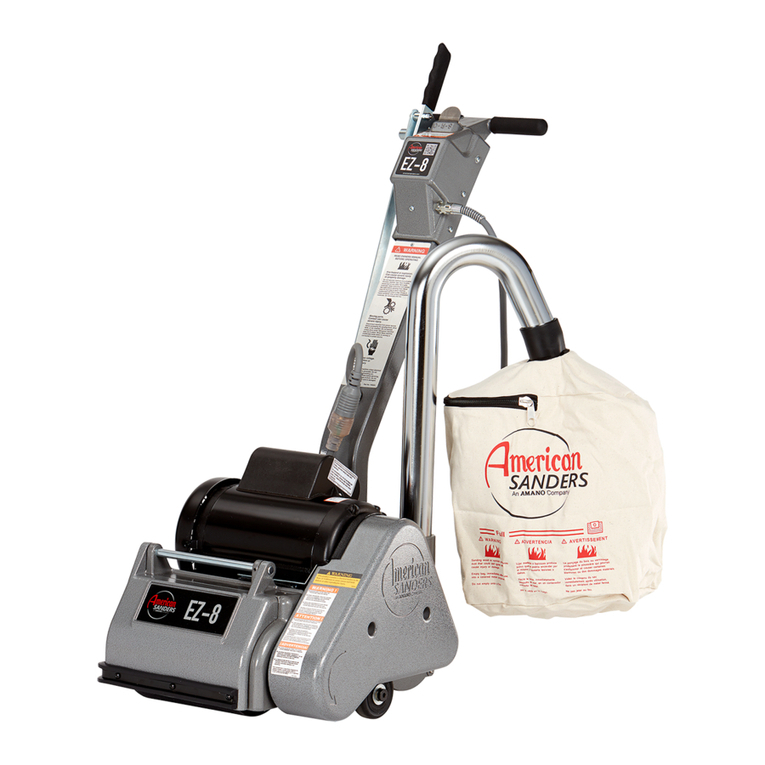
Amano American SANDERS EZ-8 User manual

Amano
Amano American Sanders OBS-18DC User manual

Amano
Amano Pioneer Eclipse 225FP16TR User manual

Amano
Amano American SANDERS EZ Sand - HDTR User manual

Amano
Amano American SANDERS FloorCrafter User manual

Amano
Amano Pioneer Eclipse PE225FP User manual

Amano
Amano American Sanders American 12 User manual

Amano
Amano American Sanders 3DS User manual
Amano
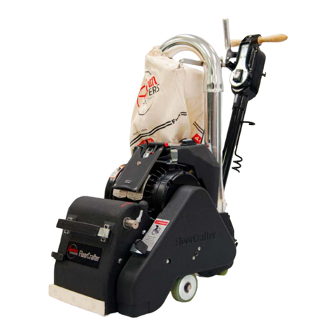
Amano American SANDERS FloorCrafter User manual


