Amano American Sanders Epoch HD User manual

Epoch HD
230V Dual Speed Rotary Sander
Operator’s Manual

READ THIS BOOK
This book has important information for the use and safe operation of this machine. Failure to read this book prior to
operating or attempting any service or maintenance procedure to your American Sanders machine could result in injury
to you or to other personnel; damage to the machine or to other property could occur as well. You must have training in
the operation of this machine before using it. If your operator(s) cannot read this manual, have it explained fully before
attempting to operate this machine.
All directions given in this book are as seen from the operator’s position at the rear of the machine.
***This product is intended for commercial use only***
WARNING!
The Products sold with this Manual contain or may contain chemicals that are known to certain governments (such as the State of
California, as identied in its Proposition 65 Regulatory Warning Law) to cause cancer, birth defects or other reproductive harm. In
certain locations (including the State of California) purchasers of these Products that place them in service at an employment job site
or a publicly accessible space are required by regulation to make certain notices, warnings or disclosures regarding the chemicals that
are or may be contained in the Products at or about such work sites. It is the purchaser’s responsibility to know the content of, and
to comply with, any laws and regulations relating to the use of these Products in such environments. The Manufacturer disclaims any
responsibility to advise purchasers of any specic requirements that may be applicable to the use of the Products in such environments.
In this Operation Manual you will find three statements that you must read and observe to ensure safe operation of this
machine.
DANGER means: Severe bodily injury or death can occur to you or other personnel if the DANGER statements
found on this machine or in this Operation Manual are ignored or are not adhered to. Read and observe
all DANGER statements found in this Operation Manual and on your machine.
WARNING means: Injury can occur to you or to other personnel if the WARNING statements found on your
machine or in the Operation Manual are ignored or are not adhered to. Read and observe all WARNING
statements found in this Operation Manual and on your machine.
CAUTION means: Damage can occur to the machine or to other property if the CAUTION statements found
on your machine or in this Operation Manual are ignored or are not adhered to. Read and observe all
CAUTION statements found in this Operation Manual and on your machine.
Operator Safety Instructions
EN
SECTION II - Parts and Service Manual
Notes ................................................................................13
Main Assembly ........................................................... 14-15
Base Assembly........................................................... 16-17
Handle Assembly........................................................ 18-19
Connection Diagram.........................................................20
Motor & Gearbox Assembly..............................................21
16" HydraSand Assembly.................................................22
20" HydraSand Assembly.................................................23
Wiring Diagrams...............................................................24
Warranty ...........................................................................25
Contents
Operator Safety Instructions...................................................2-5
Machine Introduction ................................................................. 6
230V Electrical Connection Instructions.................................... 6
Machine Set-up ......................................................................7-8
Operating Instructions ............................................................... 9
Maintenance....................................................................... 10-11

3
EN
DANGER: Failure to read the Owner’s Manual prior to operating or servicing your American Sanders machine could result in injury to
you or to other personnel; damage to the machine or to other property could occur as well. You must have training in the
operation of this machine before using it. If you or your operator(s) cannot read English, have this manual explained fully
before attempting to operate this machine.
DANGER: A. Sanding/nishing wood oors can create an explosive or combustible environment. Do not operate this machine around
solvents, thinners, alcohol, fuels, oor nishes, wood dust or any other ammable materials. Cigarette lighters, pilot lights,
electrical sparks and all other sources of ignition should be extinguished or avoided. Keep work area well ventilated.
B. Dust generated from sanding wood oors can spontaneously ignite or explode. Promptly dispose of any sanding dust in
a metal container clear of any combustibles. Do not dispose in a re.
DANGER: A. Electrocution could occur if the machine is being serviced while the machine is connected to a power source. Disconnect
the power supply before servicing.
B. Electrocution or re could occur if the machine is being operated with a damaged power cord. Keep the power cord clear
of the pad. Always lift the cord over the machine. Do not move the machine by the power cord.
C.Shock hazard. Do not use the machine if it has been rained on or sprayed with water.
DANGER: To avoid injury keep hands, feet, and loose clothing away from all moving parts on the machine. Disconnect the power cord
before replacing the pad, changing the abrasive, or when servicing. Do not operate the machine unless all guards are in
place. Never leave the machine unattended while connected to a power source.
WARNING: Injury can occur if protective clothing or equipment is not used while sanding. Always wear safety goggles, protective
clothing, and dust mask while sanding.
WARNING:
This sander is not to be used on pressure treated wood. Some pressure treated woods contain arsenic and sanding
pressure treated wood produces hazardous dust. Inhaling hazardous dust from pressure treated wood can cause serious
injury or death. Sanding pressure treated wood decks or uneven surfaces can damage the sander which is not covered
under warranty or damage waiver.
WARNING: Any alterations or modications of this machine could result in damage to the machine or injury to the operator or other
bystanders. Alterations or modications not authorized by the manufacturer voids any and all warranties and liabilities.
WARNING: Risk of explosion. Floor sanding can result in an explosive mixture of ne dust and air. Use oor sanding machine only in a
well-ventilated area free from any ame or match.

4
EN

5
EN
6
Introduction
EN
The Epoch is a oor sanding machine. It can also be used for polishing, bufng and stripping. The machine can be used on wood, vinyl, terrazzo or cement oors.
CAUTION: Your equipment may be inappropriate on some installations. Always consult with the ooring manufacturer on the proper
installation, preparation, and nishing of their product. Determine suitability of your equipment in preparing the product.
Model
07233A
EPOCH HD 16"
with HydraSand
07237A
EPOCH HD 16"
without HydraSand
07233C
EPOCH HD 16"
with HydraSand
(CSA)
07234A
EPOCH HD 20”
with HydraSand
07238A
EPOCH HD 20”
without HydraSand
07234C
EPOCH HD 20”with
HydraSand (CSA)
Voltage (Volts) 230 230 230 230 230 230
Frequency (Hz) 60 60 60 60 60 60
Current (Amps) 14 14 14 15 15 15
Power (HP) 2.5 (1.86 kw) 2.5 (1.86 kw) 2.5 (1.86 kw) 2.5 (1.86 kw) 2.5 (1.86 kw) 2.5 (1.86 kw)
Pad Driver
Diameter (in) 16 (401mm) 16 (401mm) 16 (401mm) 20 (508 mm) 20 (508 mm) 20 (508 mm)
Pad Speed (rpm) 175 or 300 175 or 300 175 or 300 175 or 300 175 or 300 175 or 300
Cord Length (ft) 50 (15.2m) 50 (15.2m) 50 (15.2m) 50 (15.2 m) 50 (15.2 m) 50 (15.2 m)
Weight (pounds)
Machine only
120 lbs (54 kg)
Machine only
120 lbs (54 kg)
Machine only
120 lbs (54 kg)
Machine only
120 lbs (56 kg)
Machine only
120 lbs (56 kg)
Machine only
120 lbs (56 kg)
Machine with weights
145 lbs (66 kg)
Machine with weights
145 lbs (66 kg)
Machine with weights
145 lbs (66 kg)
Machine with weights
150 lbs (68 kg)
Machine with weights
150 lbs (68 kg)
Machine with weights
150 lbs (68 kg)
Machine with weights
& HydraSand
158 lbs (72 kg)
Machine with weights
& HydraSand
158 lbs (72 kg)
Machine with weights
& HydraSand
158 lbs (72 kg)
Machine with weights
& HydraSand
169 lbs (72 kg)
Machine with weights
& HydraSand
169 lbs (72 kg)
Machine with weights
& HydraSand
169 lbs (72 kg)
Extension Cords (230V)
Use only an approved extension cord with two main conductors and one earthing conductor.
WARNING: If you use an extension cord, use an extension cord with minimum wire size 10 AWG. Do not use an extension cord longer
than 50 ft. Do not join two extension cords.
WARNING: Do not cut, remove, or break the ground terminal. Do not try to fit a three-terminal plug into a receptacle or connector body
that does not fit the plug. If the receptacle or connector body does not fit the plug, see your Authorized person to make
the connection.
Electrical Connection Instructions (230V)
This product must be grounded. If it should malfunction or breakdown, grounding provides a path of least resistance for electric current to reduce the
risk of electrical shock. This product is equipped with a cord having an equipment-grounding conductor and grounding plug. The plug must be inserted
into an appropriate oulet that is properly installed and grounded in accordance with all local codes and ordinances.
WARNING: Improper connection of the equipment-grounding conductor can result in a risk of electric shock. Check with qualied
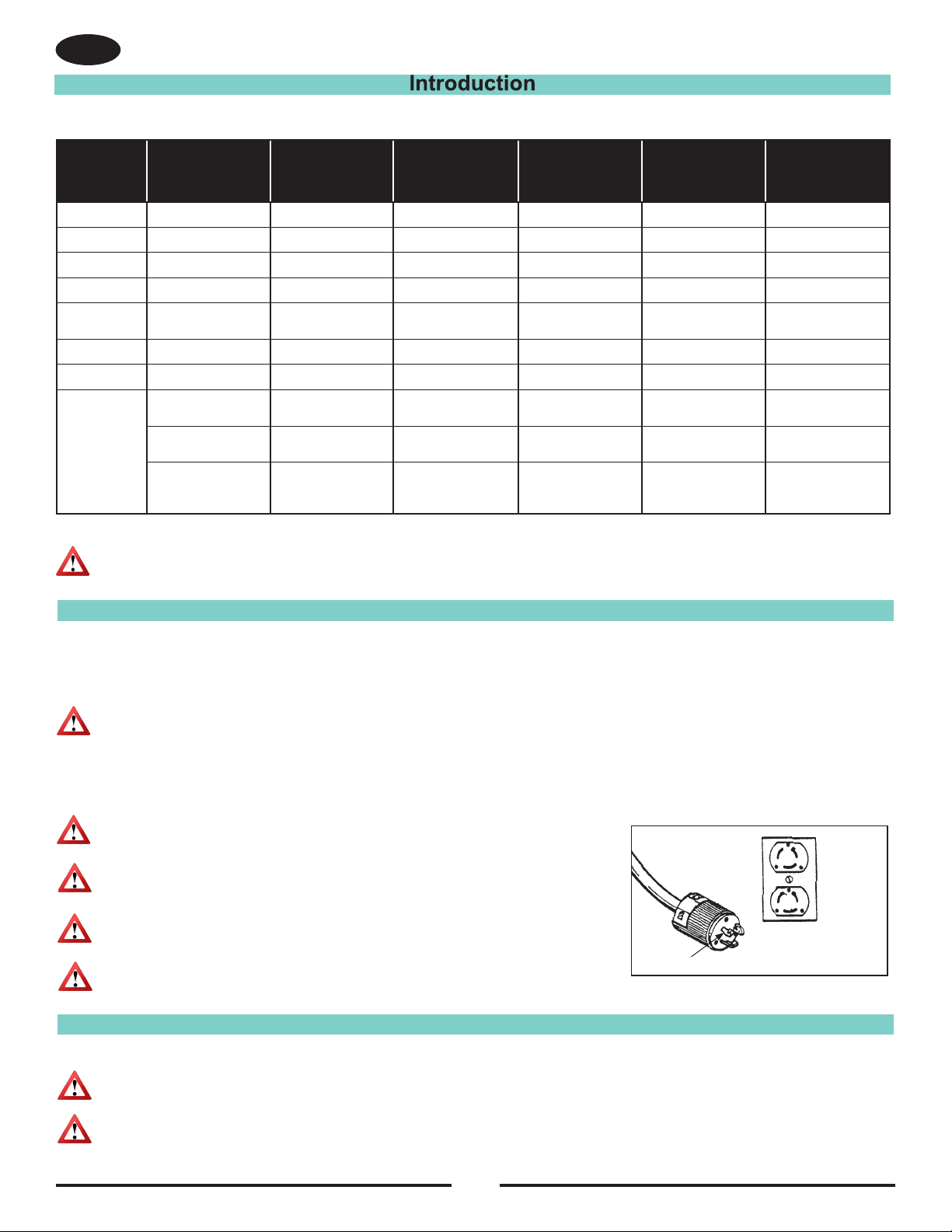
This product is for use on a nominal 230 volt circuit and has a grounding attachment plug that looks like the plug illustrated in Fig. 12. Make sure that
the product is connected to an outlet having the same conguration as the plug. No adaptor should be used with this product.
WARNING: To prevent possible electric shock, protect the machine from rain.
Keep the machine in a dry building.
WARNING: To prevent possible electric shock, always use a 3-wire electrical
system connected to the electrical ground. Consult your electrical contractor.
WARNING: Do not cut, remove or break the ground pin.
If the outlet does not t the plug, consult your electrical contractor.
WARNING: Have worn, cut or damaged cords replaced by an authorized service person.
Instructions for connection to the power supply and the electrical ground.
Figure 12
Grounded
Outlet
Grounding
Pin
Grounded
Outlet
Box
electrician or service person if you are in doubt as to whether the outlet is properly grounded. Do not modify the plug
provided with the product - if it will not t the outlet, have a proper outlet installed by a qualied electrician.

7
Machine Set-up
EN
WARNING:
Always remove the electrical plug from the electrical outlet before installing or
changing the sandpaper.
How To Install The Sandpaper (HydraSand)
To install the sandpaper, follow this procedure:
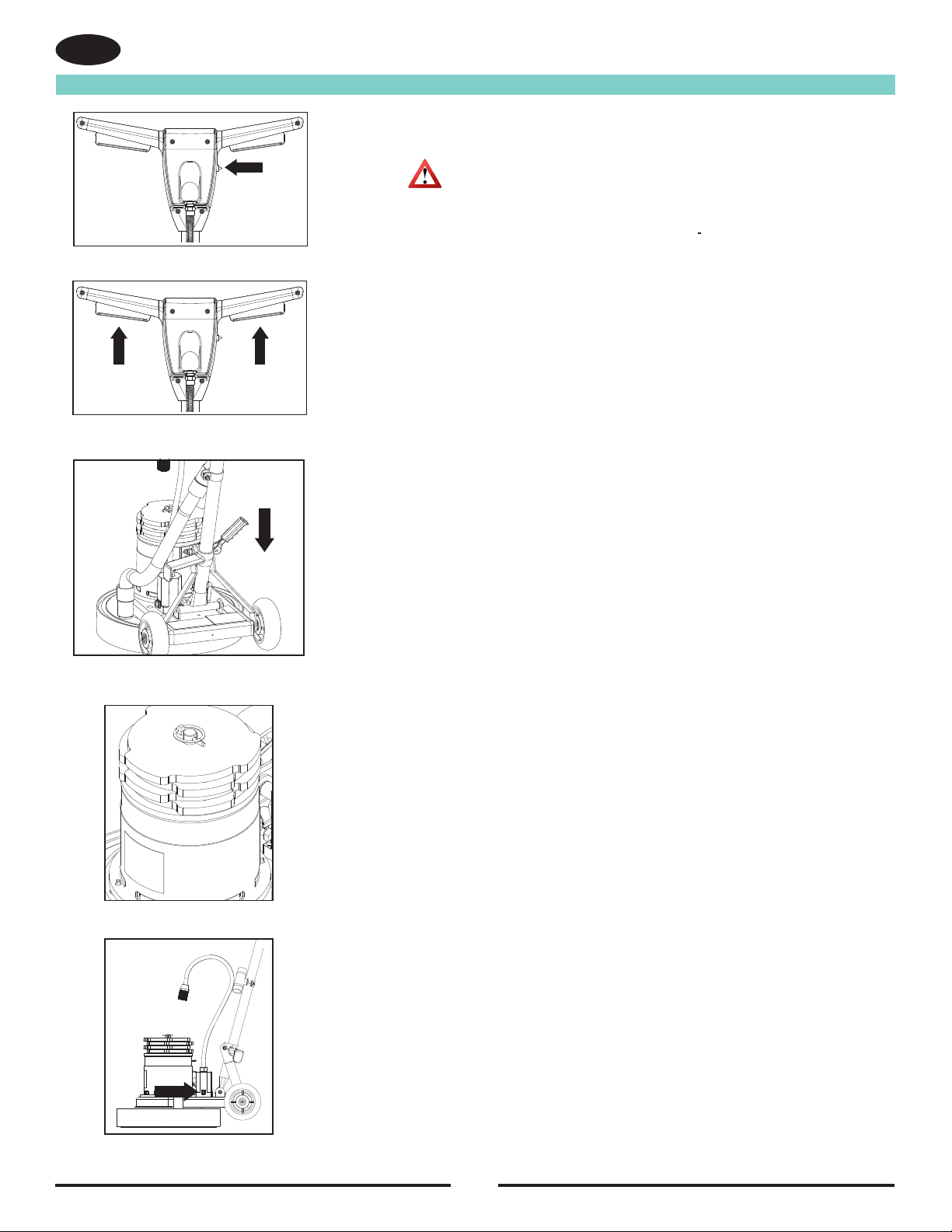
1. Put the handle in the vertical position.
2. Lock the handle. To lock the handle, push the locking lever down. See gure 1.
3. Tilt the machine backward until the handle is on the oor.
4. Put one foot on each side of the machine.
5. The HydraSand sanding head utilizes hook and loop style sanding paper. Pull off the pad hook the spent
abrasive
6. Replace with new sanding abrasive. See gure 1A.
How To Install The Sandpaper (Alternate Hard Plate)
1. Put the handle in the vertical position.
2. Lock the handle. To lock the handle, push the locking lever down. See gure 1.
3. Tilt the machine backward until the handle is on the oor.
4. Put one foot on each side of the machine.
5. Using a 7/8 wrench, remove the nut and the washer that hold the paper holder.
See gure 2.
6. Put the sandpaper on the sanding pad.
7. Put the paper holder in position. See gure 3.
8. Install the washer and the nut that hold the paper holder.
Two Speed Selection
This machine comes equipped with a selector switch for 175 or 300 RPM operation.
See gure 4 for location of speed switch.
175 RPM speed selection is for use with ner grit sanding abrasive (100 grit or greater) to help reduce the effects
of abrasive heat on the wood that can lead to closing wood pours and discoloration from burnishing the woods
surface. This speed is also used for bufng and polishing.
300 RPM operation will yield the greatest wood removal and productivity and can successfully be used with
more course grit abrasives. (80 grit or below)
CAUTION: Wood species differ greatly in their sanding characteristics, always test the speed
selection with any grit abrasive used to understand how the wood will react. The general guidelines
given here may not be appropriate for your conditions.
CAUTION: Do not use the 175 RPM setting for 80 grit or lower. This could result in an over-current
condition.
Sanding Cuts and Sandpaper
Initial Cut
The purpose of the initial cut is to remove old nish and gross imperfections on the oor surface. A coarse
abrasive should be used.
If glazing, loading, or burning takes place immediately into an initial cut, select a coarser abrasive. If this should
occur during an initial cut, the abrasive has dulled and must be replaced.
Final Cuts
The purpose of a nishing cut is to remove the scratches produced during the initial cut. Use a ne (60-80 grit)
grain abrasive.
If the surface remains rough after a nishing cut, it may be necessary to use an even ner grain of abrasive (80-
100 grit). Care should be taken in selecting the grit size of the abrasive. A very ne grain will close the pores on
a wood oor making admission of a stain difcult. Note some ner grain abrasives may begin to heat the woods
surface and burnish the wood grain. use the low motor speed to help avoid this result.
Figure 2
Figure 1
Figure 1A
Figure 4
Figure 3

8
Machine Set-up
EN
WARNING: Always remove the electrical plug from the
electrical outlet before installing or changing
the pad or brush.
How To Install The Brush Or Pad Driver
To install the brush or pad driver, follow this
procedure:
1. Put the handle in the vertical position.
2. To lock the handle, push the locking lever down.See gure 5.
3.
Tilt the machine backward until the handle is on the oor. See gure 6.
4. Put one foot on each side of the machine. See gure 6.
5. Align the lugs (1) on the locking plate into the pad driver adapter
openings (2). See gure 7.
6. To lock the brush or pad into position, turn the brush or pad driver
clockwise.
7. Turn the brush or pad counterclockwise to unlock and remove the
brush.
8. Lift the machine to the vertical position.
NOTE: To prevent damage to the brush or pad driver, remove the
accessory while not in use. Keep the brush in a cool, dry place.
How To Adjust The Handle
To adjust the handle, follow this procedure:
1. The locking lever is on the lower part of the handle tube. Use your
foot to lift the lever. See gure 5.
2. Lower the handle to the best operating position.
NOTE: For the best operating position, keep your back straight, bend
only your arms.
3. Using your foot, push the locking lever down.
4. Hold the handle against your body for the best control.
Figure 5
Figure 6
Figure 7
1. The lugs.
2. The drive adpater openings.
9
WARNING: Never start machine when the handle is in the vertical
position.
The switch to start and stop the machine is activated by the interlock switch (Fig. 8) and
the levers (Fig 8A) under the handle grips.
To start the machine, follow this procedure:
1. Lower the handle
2. Lock the handle in the best position for operation. (Fig. 9)
NOTE: Make sure you hold the handle with both hands.
3. Push the interlock switch (Fig. 8), and apply pressure to the levers
(Fig. 8A).
How To Control The Machine
NOTE: Sanding operations create higher torque conditions than normal oor polishing.
Make sure you rmly grip the handle with both hands.
The side to side movement of the machine is controlled by raising the handle and pressing
down on the handle. To move the machine to the left, press down on the handle slightly.
To move the machine to the right, raise the handle slightly.
Adding And Removing Additional Weight
This Machine comes with four (4) 6.25 pound (2.8 kg) removable weights for a total of
25 pounds (11.3 kg) maximum that can be added to increase the PSI load and abrasive
performance. See gure 10.
Caution should be used if adding weight to the machine as this increases the torque
required to turn the abrasive, thus increasing the amperage required by the motor to
perform the sanding operation.
Floors with nish or residue like sealers increase the resistance on the abrasive; adding
weight in this condition can overload the motor and trip a 20 amp circuit breaker.
Should this occur allow 15 minutes for the machine and breaker to cool. Remove additional
weight and operate the machine in the 300 rpm setting to reduce the load placed on the
motor.
How To Use The Lamp
To Position the Lamp
1. The attached LED lamp will only operate when the machine is plugged in.
2. Bend the exible arm of the lamp to the desired position.
3. Press the “ON” switch at the base of the lamp attached to the frame of the machine.
See gure 11.
Operating Instructions
EN
Figure 8
Figure 8A
Figure 9
Figure 11
Figure 10

10
EN
Maintenance
WARNING: Maintenance must be done by authorized personnel only.
CAUTION:
Keep all adjustments according to specications.
Maintenance Instructions
Return the machine to a American Sanders Authorized Service Location every 12 months for maintenance inspections.
Switches
WARNING: All electrical repairs must be done by authorized personnel only. The machine must be tested after electrical
repairs to make sure it is safe to operate. Disconnect the electrical plug from the electrical outlet before doing
any electrical repairs.
The start and stop switch has an interlock which prevents the contacts from being closed. If any part of the switch is not operating, replace the
part. If any part of the electrical system of the machine is not operating or is damaged, replace the part. Make sure all connections are tight.
Return the machine to the American Sanders Service Branch or a American Sanders Authorized Service Center for electrical repairs or testing.
Maintenance Of The Motor
If repairs to the gear unit or motor are needed, do not disassemble the gears and motor. Return the machine to the nearest American Sanders
Service Branch or American Sanders Authorized Service Center.
For safe operation, and longer life to your American Sanders product, use only American Sanders parts.
NOTE: The grease (503802) for the gear box needs to be changed every year. The Epoch requires 8 oz. of grease.

11
EN
Problem Possible Cause Solution
Machine will not start
No power Check the main power supply (building circuit breaker).
Check the cord connection at the wall outlet
Switch lever safety lock not
depressed
Hold in the switch lever safety lock and then engage
switch levers.
Bad connection Check the motor and cord interlock connections.
Bad motor speed selector
switch
Change the motor speed. If motor runs, change the
speed selector switch.
Defective Switch Check and replace if necessary.
Motor runs sluggish
Low voltage
Using extension cord with wire smaller than 10/3.
Replace with a 10/3 extension cord.
Using more than one extension cord. Only use one 50ft
10/3 extension cord.
Electrically connect to American Sanders Power
Booster.
Motor carbon brushes are worn Check and replace if necessary.
Defective handle switch Check and replace if necessary.
Bad rectier Contact an authorized American Sander Dealer.
Fuse / circuit breaker repeatedly trips
Low voltage
Eliminate extension cord & locate a power source closer
to work site.
Have voltage checked by a qualied electrican.
Electrically connect to American Sanders Power
Booster.
Not on a dedicated circuit Make sure there is no other items using power on the
circuit.
Motor is overloaded
Remove weights.
Switch to high speed, especially if using paper lower
than 100 grit or if removing nish.
Bad connection Contact an authorized American Sander Dealer.
Defective motor Contact an authorized American Sander Dealer.
Machine wobbles during operation
Defective pad One side is more dense than the other. Replace pad.
Machine left setting on pad for
extended time Pad has taken "a set". Replace pad.
Warped block on brush or
padholder Check and replace if necessary.
Block not installed properly Remove and install properly.
HydraSand head damaged. Inspect head and repair or replace
Light does not work Light switch not turned "ON". Turn "ON" light.
Light damaged Check and replace if necessary.
Maintenance

52
FloorCrafter
Belt Sander
Parts Manual
Notes:
________________________________________________
________________________________________________
________________________________________________
________________________________________________
________________________________________________
________________________________________________
________________________________________________
________________________________________________
________________________________________________
________________________________________________
________________________________________________
________________________________________________
________________________________________________
________________________________________________
________________________________________________
________________________________________________
________________________________________________
________________________________________________
________________________________________________
________________________________________________
________________________________________________
________________________________________________
________________________________________________

13
52
FloorCrafter
Belt Sander
Parts Manual
Notes:
________________________________________________
________________________________________________
________________________________________________
________________________________________________
________________________________________________
________________________________________________
________________________________________________
________________________________________________
________________________________________________
________________________________________________
________________________________________________
________________________________________________
________________________________________________
________________________________________________
________________________________________________
________________________________________________
________________________________________________
________________________________________________
________________________________________________
________________________________________________
________________________________________________
________________________________________________
________________________________________________
Epoch HD
Operator’s Manual

14
Main Assembly
EN
RF079200 122019
19
13
14
15
17
16
6
8
7
11
12
10
20
21
23
3
1
9
22
4
18
27
14
26
29
19
25
24
29
28
31
30
32
2
5

15
Main Assembly
EN
PARTS LIST
DESCRIPTION
PART
NUMBER
QTY
ITEM
HANDLE ASM., SANDERS, 07233AAS042200
CORD SET-HARD SERVICE (50 FT)
42200A
BUSHING NYLON C2K50794A
MOTOR, GEAR, 2.5HP, 230V, 2SPDAS041300
DECAL, AMERICAN SANDERS, 3"AS013600
SEAL FOAM52368A
WLDMNT DUST SHIELD
10241A
SHIELD, DUST, 20", WELDMENT (20" MODELS ONLY)AS058500B7 1
1 1
2 1
3 2
4 1
5 1
6 1
7 1
8 1
9 1
BUMPER 1730381A
BUMPER, SHROUD, 20"(20" MODELS ONLY)AS058700
B8 1
SHIELD INNER RS 16DC61832A
SHIELD, INNER, 20"(20" MODELS ONLY)AS058600
B9 1
SCREW, 5/16-18 X 2 1/2", SHCS, W/ DOG PTNB07380001 4
WASHER 5/16 SAE FLAT98065111 4
WASHER, LOCK, 5/16
98065221 4
PLATE, WEIGHT, BRACKET, 7.8" DIA.AS02500031 1
SCREW, SOCKET, FLAT, 10-32 X 3/4, CS, SS
NB07350041 7
ROD, WEIGHT, BRACKET, THREADEDAS02510051 1
PIN, LYNCH, 1/4" X 1 3/4"NB04630061 1
WEIGHT, 8" DIA, W/ RUBBER FEETAS027200
4
17
FEET, RUBBER, .81"OD, .12" H, BLACK (NOT SHOWN-
3 REPLACEMENT FEET PER WEIGHT )
AS02520012
-
LIGHT, LED, 35 DEG., 230V, ASMAS04210081 1
BULB, LIGHT, LED (NOT SHOWN)AS027600
1
-
TRANSFORMER, LIGHT, LED, 230V (NOT SHOWN)AS0286001
-
SHADE, LIGHT, LED (NOT SHOWN)AS0278001
-
TRANSFORMER HOUSING, LIGHT, LED (NOT SHOWN)AS027900
1
-
SOCKET WIRE ASM, LIGHT, LED (NOT SHOWN)AS0280001
-
ROCKER SWITCH, LIGHT, LED (NOT SHOWN)AS028100
1
-
SWITCH COVER, LIGHT, LED (NOT SHOWN)AS0282001
-
SCREW, 8-32 X 1", RH, PHILLIPSNB07390091 8
SKIRT, RS-16DC
30725A
SKIRT, 20" DIA X 3.25"H, VINYL (20" MODELS ONLY)
AS059920
02 1
B02 1
SKIRT, 20" DIA X 3"H, FABRIC (20" MODELS ONLY)
AS058800
C02 1
ASSY PAD DRIVER
10242A12 1
DRIVER, PAD, 20", MIGHTY-LOK (20" MODELS ONLY)AS042500B12 1
PLATE, DRIVE, HYDRA SAND, KITSA03160022 1
HYDRASAND 20" KIT (20" MODELS ONLY)SA035400
B22 1
1.5" X 30" CUFFS BE BLACK30408B32 1
GROMMET, 11/16 X 1
NB00990042 1
CONDUIT CONNECTOR 3/8" 2-SCREW17063752 1
BASE, CONTACTOR BOX,W/INSERTSAS04340062 1
COVER, CONTACTOR BOX,W/INSERTSAS043500
72 1
CONTACTOR, 2-POLE, 230V, 40AAS04160082 1
NUT, KEPS, 10-32
NB00660092 8
WASHER, LOCK 1/4"98065703 2
WASHER 1/4 SAE FLAT PLTD98064613 2
SCREW 1/4-20 X 3/4 HX SZ CAP
85806A23 2
RF079200 072420
16
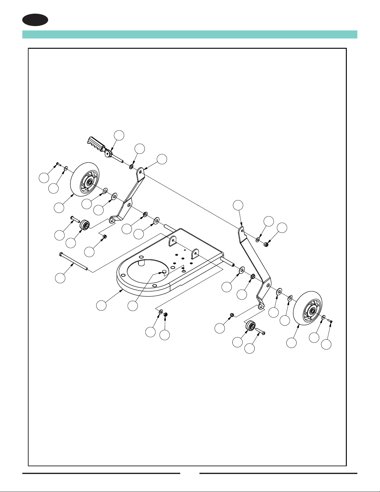
Base Assembly
EN
RF078900 121919
15
16
8
9
14
6
14
6
9
8
2
16
15
2
3
4
12
10
11
13
7
17
15
12
20
18
19
20
18
19

17
Base Assembly
EN
PARTS LIST
DESCRIPTION
PART NUMBER
QTY
ITEM
FRAME, EPOCH, W/ INSERTSAS02710011
WHEEL, PERFORMA, 6" GREYRV00960022
ARM, LINK, RIGHT, EXTENDED,PLTAS04380213
ARM, LINK, LEFT, EXTENDED,PLT
AS043902
14
PLUG-BUTTON
57120A15
BUSHING, FLANGED, BRONZE, 1/2 ID X 1/4 LMP16540026
SCREW 3/8-16 X 680087A1
7
WASHER BOWED .516ID X 1.06OD80295A28
WASHER, FLAT, 1/2", SSNB03460029
NUT LK 3/8 -16 REG
920342110
WASHER WEAR CAM
980349111
WASHER, 3/8" SAE, FLAT980645212
CAM ASSY WITH GRIP56109699113
WASHER FLT 1.25X .52 X .06 NYLON87607A214
SCREW 10-32 X 3/4 PAN HD85383A215
WASHER FLAT 10 TYPE B WIDE
80291A216
NUT 3/8-16 ESNA LIGHT
920248117
WHEEL, PERFORMA, 1 5/8 X 7/8MP246200218
SCREW, BH, 5/16-18 X 1 3/4NB3003219
NUT, 5/16-18 HEX LOCK920110220
RF078900 121919

18
Handle Assembly
EN
RF078800 100719
4
4
2
10
16
6
5
13
15
14
3
8
9
11
12
1
7
19
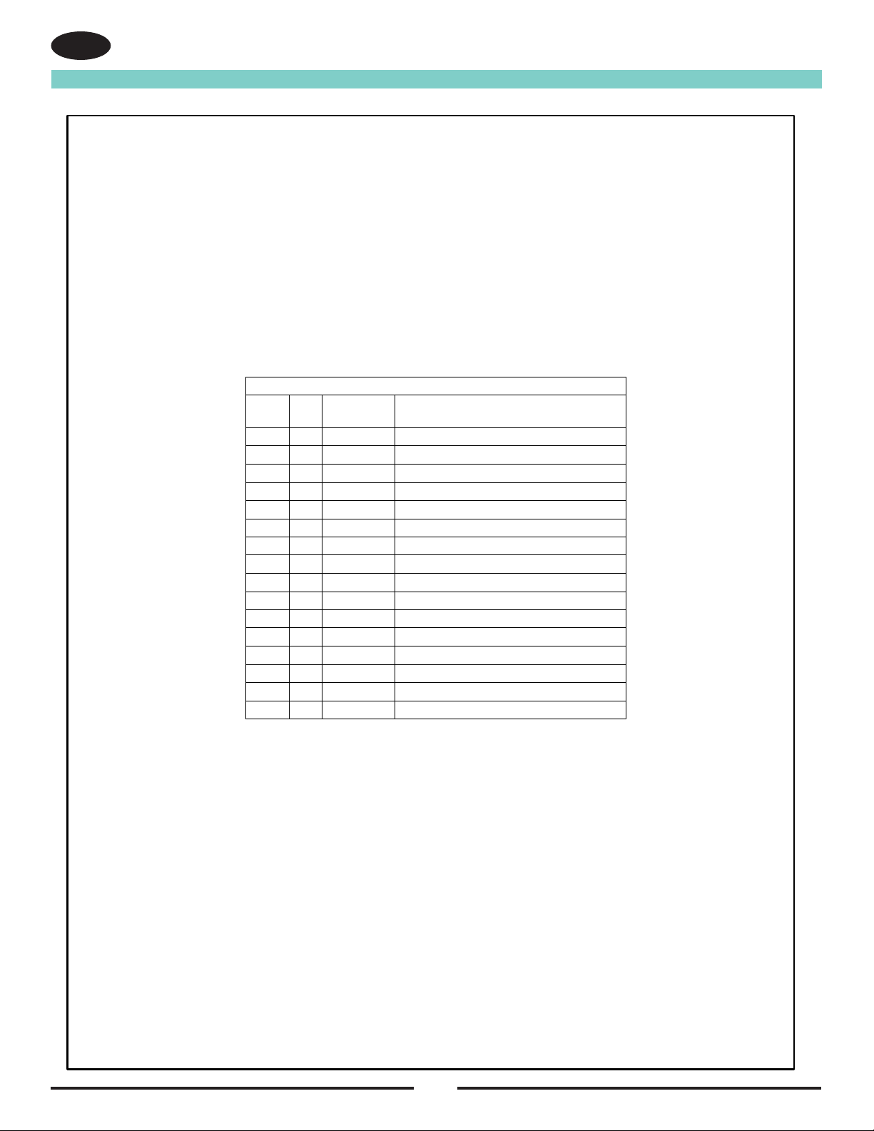
Handle Assembly
EN
Parts List
DESCRIPTION
PART
NUMBER
QTY
ITEM
HANDLE FRONT CFP
21074A11
HANDLE BACK CFP21075A12
CLAMP HANDLE C2K50781A13
SCREW 10-32UNF X .75 HRCS80284A64
SCREW 10-32 X 3/8 HRCS
80290A15
WASHER FLAT 10 TYPE B WIDE
80291A16
MODULE INTERLOCK ASM.AS0345001
7
TUBE, HANDLE, 1600AS02950018
BUSHING CORD C2K50796A19
CORD, ADAPTER, 60", 12/3AS042000110
CORD, INTERCONNECT, 46", 18/4AS041900
111
DECAL, HANDLE, EPOCH HDAS042600
112
ADAPTER, HOSE, SANDER, WELD.10304A113
BOLT, CARRIAGE, 5/16-18 X 1 1/288643A114
NUT, 5/16-18 HEX LOCK920110115
LABEL CCA WARNING71347A116
RF078800 100719
20
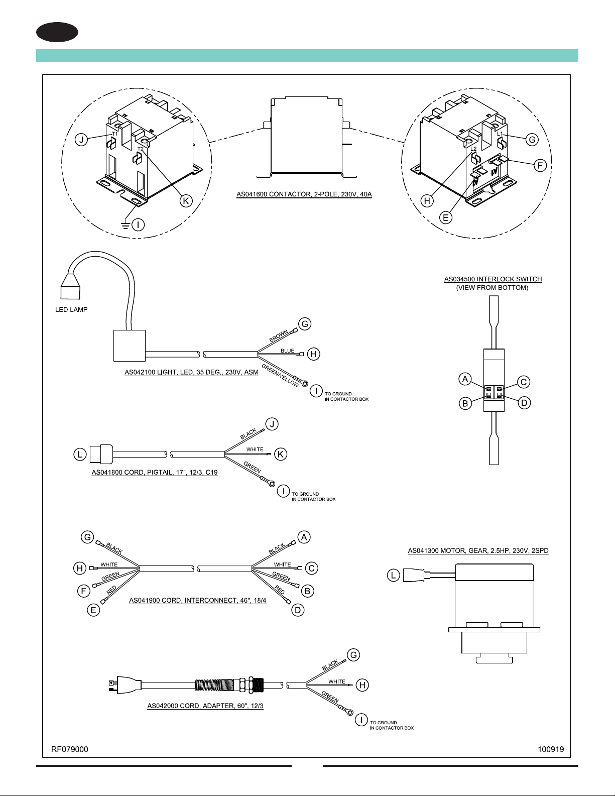
Connection Diagram
EN
This manual suits for next models
1
Table of contents
Other Amano Sander manuals

Amano
Amano American SANDERS EZ-8 User manual

Amano
Amano Pioneer Eclipse PE225FP User manual

Amano
Amano American Sanders American 12 User manual

Amano
Amano American SANDERS EZ Sand - HDTR User manual

Amano
Amano Pioneer Eclipse 225FP16TR User manual

Amano
Amano American Sanders 3DS User manual

Amano
Amano American Sanders OSB-18 User manual

Amano
Amano American Sanders OBS-18DC User manual

Amano
Amano American SANDERS FloorCrafter User manual

Amano
Amano American SANDERS FloorCrafter User manual


