Amano American SANDERS FloorCrafter User manual

Belt Sander
FloorCrafter
Operator’s Manual

Contents
Operator Safety Instructions...................................................... 3-6
Introduction................................................................................... 7
Machine Specifications................................................................. 7
230V Electrical Schematic............................................................ 7
Machine Transportation............................................................. 8-9
Machine Setup ........................................................................ 9-10
Machine Operation ................................................................ 11-12
Chatter-Wave Prevention ........................................................... 13
Sanding Cuts & Sandpaper........................................................ 13
Sander Adjustment Procedure ................................................... 14
Routine Maintenance ................................................................. 16
Troubleshooting..................................................................... 17-18
Wiring Diagram........................................................................... 53
Handle Assembly................................................................... 54-55
Base Assembly...................................................................... 56-57
Belt Tensioner Assembly ....................................................... 58-59
Dolly Assembly ...................................................................... 60-61
Dust Control Assembly......................................................... 62-63
Motor Assembly..................................................................... 64-65
Sanding Drum Assembly....................................................... 66-67
READ THIS BOOK
This book has important information for the use and safe operation of this machine. Failure to read this book prior to
operating or attempting any service or maintenance procedure to your American Sanders machine could result in injury
to you or to other personnel; damage to the machine or to other property could occur as well. You must have training in
the operation of this machine before using it. If your operator(s) cannot read this manual, have it explained fully before
attempting to operate this machine.
All directions given in this book are as seen from the operator’s position at the rear of the machine.
***This product is intended for commercial use only***
WARNING!
The Products sold with this Manual contain or may contain chemicals that are known to certain governments (such as the State of
California, as identied in its Proposition 65 Regulatory Warning Law) to cause cancer, birth defects or other reproductive harm. In
certain locations (including the State of California) purchasers of these Products that place them in service at an employment job site
or a publicly accessible space are required by regulation to make certain notices, warnings or disclosures regarding the chemicals that
are or may be contained in the Products at or about such work sites. It is the purchaser’s responsibility to know the content of, and
to comply with, any laws and regulations relating to the use of these Products in such environments. The Manufacturer disclaims any
responsibility to advise purchasers of any specic requirements that may be applicable to the use of the Products in such environments.
In this Operation Manual you will find three statements that you must read and observe to ensure safe operation of this
machine.
DANGER means: Severe bodily injury or death can occur to you or other personnel if the DANGER
statements found on this machine or in this Operation Manual are ignored or are not adhered to. Read
and observe all DANGER statements found in this Operation Manual and on your machine.
WARNING means: Injury can occur to you or to other personnel if the WARNING statements found on
your machine or in the Operation Manual are ignored or are not adhered to. Read and observe all
WARNING statements found in this Operation Manual and on your machine.
CAUTION means: Damage can occur to the machine or to other property if the CAUTION statments found
on your machine or in this Operation Manual are ignored or are not adhered to. Read and observe all
CAUTION statments found in this Operation Manual and on your machine.
Operator Safety Instructions
EN
4
EN
DANGER: Failure to read the Owner’s Manual prior to operating or servicing your American Sanders machine could result in
injury to you or to other personnel; damage to the machine or to other property could occur as well. You must have
training in the operation of this machine before using it. If you or your operator(s) cannot read English, have this
manual explained fully before attempting to operate this machine.
DANGER: A Sandingnishing ood oors can create an eposie or comustie enironment Do not operate this machine
around soents thinners acoho ues oor nishes ood dust or an other ammae materias igarette
lighters, pilot lights, electrical sparks and all other sources of ignition should be extinguished or avoided. Keep
work area well ventilated.
Dust generated rom sanding ood oors can spontaneous ignite or epode rompt dispose o an sanding
dust in a meta container cear o an comusties Do not dispose in a re
DANGER: A. Electrocution could occur if the machine is being serviced while the machine is connected to a power source.
Disconnect the power supply before servicing.
Eectrocution or re coud occur i the machine is eing operated ith a damaged poer cord eep the poer
cord clear of the drum. Always lift the cord over the machine. Do not move the machine by the power cord.
Shoc haard Do not use the machine i it has een rained on or spraed ith ater
DANGER: To avoid injury keep hands, feet, and loose clothing away from all moving parts on the machine. Disconnect the
power cord before changing the abrasive or when servicing. Do not operate the machine unless all guards are in
place. Never leave the machine unattended while connected to a power source.
WARNING: Injury can occur if protective clothing or equipment is not used while sanding. Always wear safety goggles,
protective clothing, and dust mask while sanding.
WARNING: This sander is not to be used on pressure-treated wood. Some pressure-treated woods contain arsenic and sanding
pressuretreated ood produces haardous dust Inhaing haardous dust rom pressuretreated ood can cause
serious injury or death. Sanding pressure-treated wood decks or uneven surfaces can damage the sander which is
not covered under warranty or damage waiver.
WARNING: An aterations or modications o this machine coud resut in damage to the machine or inur to the operator or
other standers Aterations or modications not authoried the manuacturer oids an and a arranties and
liabilities.
WARNING: Ris o eposion oor sanding can resut in an eposie miture o ne dust and air Use oor sanding machine
only in a eentiated area ree rom an ame or match

5
EN
WARNING: Read all safety warnings and instructions. ue to oo tucto eut eectc hock e
and or serious injury.
Save all warnings and instructions for future use.
Safety Warnings For Sanding Operations
1 h oe too tee to ucto e e et tucto eccto oe th th oe
too ue to oo tucto te eo eut eectc hock e o eo u
2. Operations such as grinding, wire brushing, polishing or cutting-off are not recommended to be performed with this power tool.
Operations for which the tool was not designed may create a hazard and cause personal injury.
3 o ot ue cceoe hch e ot ecc ee ecoee the too uctue ut ecue the cceo c
be attached to your power tool does not assure safe operation.
4. Wear personal protective equipment. Depending on application, use face shield, safety goggles or safety glasses. As appropriate, wear
ut k he otecto oe okho o ce o to e eete ou oeto he ee
otecto ut e ce o to e eete ou oeto he ut k o eto ut e ce o
te tce eete ou oeto ooe exoue to hh tet oe cue he o
5. Keep bystanders a safe distance away from work area. Anyone entering the work area must wear personal protective equipment.
et o ok ece o oke cceo cue u eo ete e o oeto
6. Hold power tool by gripping insulated surfaces (handle) only, when performing an operation where the cutting accessory may contact
he o t o co utt cceo cotct e e ke exoe et t o the oe too e hock
the operator.
oto the co ce o the u ou oe coto the co e cut o e the oeto o othe cou e hocke
by a live wire.
8 o ot oete the oe too e e te k cou te thee te
k o exoo oo c eut exoe xtue o e ut e oo che o
e-ette e ee o e o tch
General Power Tool Safety Warnings

6
EN
Additional Rules For Safe Operation
1. Empty the dust bag or dust collection receiver frequently. Do not leave residue in dust bag or dust collection receiver unattended.
A et to o-coute et cote oo o h ouce ut tht c e te cue u o
damage. Always empty dust bags or collection receiver before storing the machine.
2 et exoe ee ooe e o ok e o ot tke et e etc th e tk et
or abrasive particles with sanding paper produces sparks that could ignite the sanding dust which can cause injury or damage.
3 o ot oete t ee oe too ee utet th uctue eccto ee tee tht
Operating a partially assembled power tool could result in injury to the operator or bystander and could cause damage to the equipment
or surroundings.
4. Do not attempt to change the sanding paper while the power tool is running. The sanding drum can snag clothing and cause injury to
limbs, and moving sanding paper can cause abrasions.
5. The power tool should only be used on an electrical system (mains) that is rated for the electrical requirements of the power tool as
ho o the ete e o o eth oue te o ot ece the oe too t eee o coecte to
eectc ccut oe ue cou cue e o eectc hock
General Power Tool Safety Warnings

AUIN: his machine i operate on on A reuenc and on eectrica otage shon on the motor namepate Mae
sure you have the correct frequency and voltage before connecting the power cord to an outlet. The machine has
a plug as shown below.
DANGER: Electrocution could occur if the machine is exposed to water or rain. Keep the machine in a dry building.
DANGER:
Electrocution could occur if machine is improperly connected to the electrical system. To prevent possible electric
shock
, always use a 3-wire electrical system connected to an electrical ground. For maximum protection against
eectrica shoc use a circuit that is protected a ground aut circuit interrupter onsut our eectrica
contractor.
DANGER: Electrocution could occur if the ground pin is tampered with in any way. Do not cut, remove, or break the ground
pin Do not tr to t a threetermina pug into a receptace or connector od other than a threepug receptace
or connector od I the outet does not t the pug consut our eectrica contractor
DANGER: Electrocution could occur if the machine is used with a damaged plug or power cord. If the cords or plugs are worn
or damaged in an a hae them repaced an authoried serice person or eectrician
oto e to o o tke coe oe te to coe u to ee euce eue
Machine Specifications
Introduction
The FloorCrafter can be used on a variety of surfaces. It is an ideal tool for wood flooring maintenance and restoration work.
7
230V Electrical Connection Instructions
This machine must be connected to an electrically grounded circuit in order to
protect the operator from electric shock. This machine has an approved power
cord with three conductors as well as a plug with three terminals. Connect the
u to thee hoe ecetce o xu otecto t eectc
shock, use a circuit that is protected by a ground fault circuit interrupter.
Etension ords
e o oe thee-oe exteo co th to coucto
and one earthing conductor. This machine is equipped
with a power cord. When greater range is needed follow the table
to determine cable gauge of additional footage. Refer to the
cht to the ht o exteo co oto
EN
Part # 07104A 07104B 07202B / 07104C 56380917
Model FloorCrafter 8 FloorCrafter 8, Blk FloorCrafter 8 FloorCrafter 8
Electrical Requirements 230~, 60Hz / 15.7 A, 3.7 kW 230~, 60Hz / 15.7 A, 3.7 kW 230~, 60Hz / 15.7 A, 3.7 kW 230~, 50Hz / 16.0 A, 3.0 kW
Sound Emission (Lpm)* 93.0 dB(A) 93.0 dB(A) 93.0 dB(A) 96.2 dB(A)
Vibration <.15 in/s <.15 in/s <.15 in/s 2.88 m/s2rms
Motor 4 ucto 4 ucto 4 ucto 3 k ucto
ontact hee Rate 2450 rpm 2450 rpm 2450 rpm 2042 rpm
Abrasive Rate 4500 ft/min 4500 ft/min 4500 ft/min 3750 ft/min
Arasie Sie 29½ x ⅞” 29½ x ⅞” 29½ x ⅞” 29½ x ⅞”
Fan Flow Rate 234 CFM 234 CFM 234 CFM 195 CFM
Drum Settings 80 lbs., 70lbs., 60 lbs. 80 lbs., 70lbs., 60 lbs. 80 lbs., 70lbs., 60 lbs. 80 lbs., 70lbs., 60 lbs.
eroad rotection Magnetic Circuit Breaker Magnetic Circuit Breaker Magnetic Circuit Breaker Magnetic Circuit Breaker
Eectric ae 0 10-3 L-20 u 0 10-3 L-20 u 0 10-3 L-20 u 100 0340 A3-20 u
perating ontros Aute Lee/ Aute Lee/ Aute Lee/ Aute Lee/
eeing ontros xte Aute xte Aute xte Aute xte Aute
Operating Wheels 80 uoete e ethe 80 uoete e ethe 80 uoete e ethe 80 uoete e ethe
Weight 204 lbs. 204 lbs. 204 lbs. 204 lbs.
Dimensions 3 x 13¾ x 38¾3 x 13¾ x 38¾3 x 13¾ x 38¾3 x 13¾ x 38¾

WARNING: The machine is heavy. Remove the motor from the machine before transporting. Get help loading the machine and
motor Use proper iting techniues
ransporting the Machine Using the Do art
AUIN: hen depoing the do the drum i contact the oor or ground oer hich the machine is resting are shoud
be taken to avoid surfaces which might damage or contaminate the drum.
AUIN: While transporting using the dolly, abrupt changes in the direction of travel or the surface over which the machine
is being transported could cause the machine to tip over. Also, the machine is more likely to tip over when
transporting across inclined surfaces.
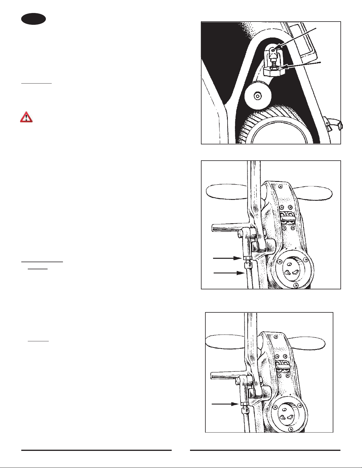
Attach the dolly to the rear of the machine as follows:
1 e the uck eee ee 2A uce the utet ut 2 to o tto o the o ee ue 2
2 et the uck eee kee to the o cket ete thte the utet ut ut the o ech ut
free.
Deploy the dolly under the machine as follows:
1. With the dolly mechanism in place as described above, tip the machine by lifting up on the operator's handle to raise the rear of the machine off
the oo/ou ut the o ue the che ee ue 3
2 o the o oto u ou oot o the che to t ck et o the o hee ee ue 4
3 the che ck o ou hee coe the uck eee ee o tot oe utet o the uck eee kee e
necessary to allow the levers to be tightened securely.
eo/to the o
he o c e toe o the che the oto o t c e eoe toe ete
1. Open the quick release levers to loosen the dolly.
2 Lt u o the oeto he to t the che o
3 the o out o ue the che oe the che ut t et o t o hee
AUIN: Be careful when lowering the machine. The dolly will swing back toward the operator as the machine is lowered.
4 o toe the o the oto the o u t the to o the e t te coe the uck eee
ee to ecue t ce ee ue
5. To remove the dolly, loosen the quick release adjustment nuts until the levers and nuts clear the counter-bore on the dolly brackets, and remove
the dolly. Tighten the adjustment nuts until the quick release levers can be closed securely.
Machine Transportation
8
Figure 2
AB BA
Figure 3
Figure 4 Figure 5
A
B
Figure 6
EN

Machine Setup
To set-up your machine, follow this procedure:
1. Familiarize yourself with the machine and read all danger,
warning, and caution statements. Make sure all operators
o th che he e th eto u the
cot e th u he the u exe u
before allowing anyone to operate the sander.
2 Locte the eectc ouce he ecetce hou
be compatible with the plug. The receptacle must be
grounded and must be fused (see nameplate for electrical
requirements) to avoid an electrical hazard.
3 the ut to the eo ee ue o the
strings on the dust bag and draw tight over the flare on the
elbow. Wrap the string around the elbow and secure.
4. Wind the electrical cord through the cable arm.
ee ue 10 ee the oe co out o th o
equipment. Do not connect the electrical cord at this time.
9
ransporting the Machine arring o eope
1 eo 1 lifts the machine by the front handle.
2 eo 2 t the che the oet he
Figure 8
Figure 7
EN
ransporting the Machine ne erson
NOTE: This is accomplished by removing the motor from the chassis
and transporting the motor and chassis separately.
To transport the machine, follow this procedure:
1. Make sure the power cable is disconnected from the electrical outlet.
2. Release the tension on the drive belts using the quick release lever.
ee ue 6A )
3. Open the belt guard by pulling on the handle immediately above the
et tuck hee ee ue 6
4. Remove the drive belts from the machine
5. Disconnect the motor pigtail from the handle pigtail if so equipped.
ee ue
6 ce the oto out ko to ooe the oto
ee ue 8
te the oto the oto t he ou e
lift the motor off the chassis and take it to the work site.
8 Lt the ch the ot e he Lt the e
and bring the belt guard against your chest. Take the chassis to the
work site.
To assemble the machine after transporting, follow this procedure:
1 e the et u oo ce the oto e o the ch
ce the oto out ko ucet to ee
secure the motor.
2 t the e et hte the et u the et teo uck
release lever.
3. Check the tension on the belts and close the belt guard door.
AUIN: remature earing aiure can occur i the an et
is set too tight he an et shoud deect at
the center of the span with 5 lbs. of pressure.
NOTE: It is necessary to adjust the fan belt independently
during this procedure or during replacement. The
idler pulley is factory adjusted.

10
Machine Setup
u the tch o to eee the cce oo to et to the che ee ue 12
6 otte the eee ee o ee ue 11
CAUTION: Damage to the sanding drum will occur if the machine is operated without a sanding belt.
Figure 11
Figure 9 Figure 10
t e e et the e oe the teo oe cotct hee ee ue 12
8. Rotate the release lever backward to tighten the abrasive belt.
AN o ot oce the eee ee o o c e the tck ech cue the e et to -tck
9. Depending on the model, the control switch is found on either the operating handle or on the motor. Verify that the control switch is set to
ee the k o the tch
10. Connect the electrical cord. On certain models, the connection must be twisted clockwise to lock.
11 o tu o oet - tet oeto the coto tch he oe the et tck oo the oceue oute the e
Autet oceue o e 16 to coect the et tck hee o e o the e o the cce oo tht oute the
belt adjustment.
12 oe the cce oo ce the e o the tch oe the keee o the cce oo uh the tch t t the
mainframe to secure.
Figure 12
EN

DANGER: Sanding/finishing wood floors can create an
enironment that can e eposie igarette
lighters, pilot lights, and any other source of
ignition can create an explosion when active
during a sanding session. All sources of
ignition should be extinguished or removed
entirely if possible from the work area.
DANGER: Work areas that are poorly ventilated can
create an explosive environment when
certain combustible materials are in the
atmosphere, i.e., solvents, thinners, alcohol,
fuels, certain finishes, wood dust and other
combustible materials. Floor sanding
machines can cause flammable material and
vapors to ignite. Read the manufacturer’s
label on all chemicals used to determine
combustibility. Keep the work area well
ventilated.
DANGER: Sanding dust can self ignite and cause an
injury or damage. Remove the contents
of the dust bag each time you finish using
the machine. Always dispose of the dust
in a metal container located outside of the
building. Never leave a dust bag unattended
with sanding dust in it. Empty the contents
frequently. Do not empty the contents of the
dust bag into a fire.
DANGER: Hitting a nail while sanding can cause sparks
and create an explosion or fire. Always use
a hammer and punch to countersink all nails
before sanding floors.
11
Operating Instructions
EN
To operate the machine follow this procedure:
1. Before sanding, decide on best approach for sanding
ee e the oo uee t e ece to
sand diagonally to the direction that the floor is laid. This
will help “pull” or stretch low and high spots in the floor
over a greater area, producing a flatter surface.
e cut hou e eoe t e
oxte 1 to the ecto o the oo ut
direction should change on successive cuts with the final
cut performed in the direction of the wood grain. This will
minimize the tendency of waves to form and provide the
most even floor surface.
When sanding the area, work so that you are moving away
from where the cord set enters the room. This will help
to avoid entanglement with the cord set and eliminate the
need to move the cord set out of the way so frequently.
Work the area in a way that avoids interruption or
termination points (an end of pass.) Make long continuous
passes.
2 ce to e o che oote the ecto
you intend to work. Rotate elbow on dust pipe until
dust bag rests on motor. This will maintain balance and
sanding pressure as the dust bag fills. The machine
should be operated with the dust bag in this position
whenever possible.
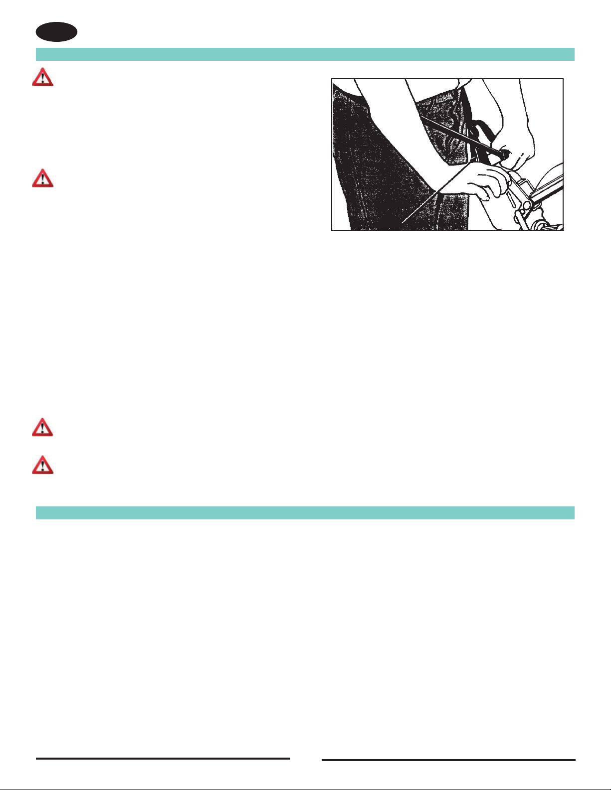
3 the oet et Aec e N 360A
used, proceed as follows:
oto the oet et ou t
b. Cross the straps at the waist.
ee ue 13
c e the et oo e oe the he o the coto
lever side. Adjust the length as needed.
d. Wrap the remaining strap around the opposite side of
the handle, and hold it in place with your hand.
6. When drum is fully engaged with the surface, gradually adjust your pace for adequate finish removal. Keep sander in motion while the drum is
engaged with the surface or dwell marks will occur.
oe the che the ecto o the the oo heee t oe the uce t cott ce
8 u ethe-cut out t the teto ot e the u u th the coto ee ee ue 13
9. Repeat technique described in steps 5, 6, 7, and 8 and sand back down pass just made. When completed, begin a new pass by overlapping
eou h the th o the e te teto ot to eet tct e to oote ette e he e
10. Empty contents of the dust bag into a metal container located outside the building. Dust bag should be emptied whenever full, as indicated on
bag.
WARNING: Serious operator injury could occur if the operator
has tied or strapped the loose end of the operator’s
belt strap to the machine. Always wrap the strap
so that you can let go and get away quickly in case
of bag fire or explosion.
4. Activate the control switch.
AUIN: o preent damage to the oor mae sure the
machine is in motion when the drum is engaged
with the floor.
5. Feather-cut in by easing the drum down onto the surface with the control
lever while the sander is in motion.
12
Operating Instructions
Figure 13
EN
WARNING:
Sanding Cuts & Sandpaper
Initia ut
he uoe o the t cut to eoe o h o eecto o the oo uce he euet hou e ute to
he eue ett coe e et hou e ue the uce eee e ee ctche eext e
k uee k etc t e ece to co o o to the to etoe eee to the uce thee coto e
not present, the initial cut should be done in the direction of the grain.
o o u tke ce ete to t cut eect coe e th hou occu u t cut the
abrasive has dulled and must be replaced.
ina uts
he uoe o h cut to eoe the ctche ouce u the t cut e e 60 - 80 t e euce
sanding pressure setting.
the uce e ouh te h cut t e ece to ue ee e o e 80 - 100 t e hou e tke
eect the t e o the e A e e coe the oe o oo oo k o o t cut
o u hou occu ete to h cut euce the eue t hou occu u h cut the e
has dulled and must be replaced.
WARNING: Do not overfill dust bag or serious fire may result. Never leave a dust bag containing dust unattended.
Sanding dust can se ignite and cause a ire or eposion Use on genuine American Sanders repacement ags
AUIN: An oeried dust ag ma eect machine aance and perormance Do not hande or distur dust ag and
elbow while sanding or damage to the floor may occur.

13
Chatter Wave Prevention
Aec e et che e ee uctue to the ot
toece oee te h cut t oe to ee chtte o e
he et utee to eoe the chtte to h the oo th ott
hoot e uch the Aec e och
To minimize chatter when using a belt or drum sander, the following steps should
be taken:
1. DRUM MARSe cue the oeto oe the u to the oo
without forward traverse. These marks should be removed by cutting at a 45
degree angle to the mark. Cutting at the mark while maintaining the same
path will only increase the mark depth and width.
ee ue 14
2. UNEEN AING SAE...can leave lengthy “waves”. The machine
cut oe te u the oe ce tcu tteto to
steady even pace.
3. EESSIE IG US...may reveal high spots on the paper/contact
wheel and cause chatter. Take a heavier cut and increase the pace.
Figure 14
RER ARE UR MAINE AN MINIMIE AER AND AES
1. V-BELTSc cue to chtte the e o o ut e o et ece Aec e
2. RU AND ASER EESth t ot out-o-oue o e hee to the uce c cue e o chtte eect
A ce ect hee eoe tt to eoe the h cut ece o tue the hee ou to e out-o-ou
Nee o the e to t o h uce o eth eo o te
3. DUS IU SES...may need adjusted differently for different materials that are to be sanded. An improperly adjusted shoe will leave
trailing debris that will be run over by the wheels and cause “random waves”.
4. NA EES DRUMS... e out-o-ou cue chtte otct ou Aec e ee o tce to tue o
replace the drum.
4. DEBRIS...lodged between the paper and the drum will leave chatter. On a belt sander, debris may be adhered to the drum.
ue the u ce ee o e eoe c the e o
5. ARASIE UAI et e c e thcke o o ut e cue chtte e o Aec e
ece e toe e cco to uctue ecoeto
EN
14
Figure 15
Figure 16
Figure 17
5. BEARINGS...in the motor, drum, or fan system may become worn and induce vibration which could cause “chatter”.
6. UES..
tht e e o eee o c uce to cue chtte otct ou Aec e ee o
assistance.
7. SANDAER ENSIN...should always be released when the machine is shut off for 10 minutes or longer to avoid compression of the drum.
NE: American Sanders is not responsie or reor o oors that are unacceptae to the customer It is our responsiiit to
insure your equipment is in proper operating order and that you use the right machine for the job.
Sander Adjustment Procedures
DANGER: Electrocution could occur if maintenance and repairs are
performed on a unit that is not properly disconnected from
the power source. Disconnect the power supply before
attempting any maintenance or service.
DANGER: Moving parts of this machine can cause serious injury and/or
damage. Keep hands, feet and loose clothing away from all
moving parts of the sander.
The following information provides details on how to adjust different features/
controls of the sander.
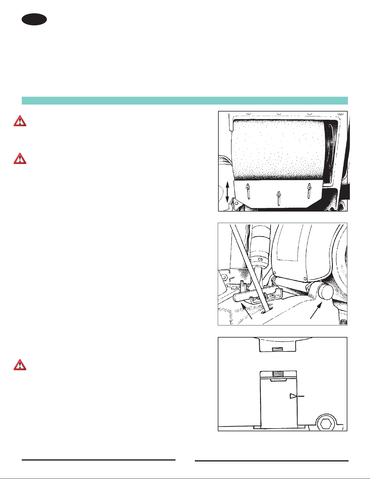
Dust Shoe
To adjust the dust shoe follow this procedure:
1. Disconnect machine from power supply.
2 Looe the thee ce te the ut hoe to the ch
3. Adjust the dust shoe down to reduce clearance.
4. Adjust the dust shoe up to increase clearance.
A the ut hoe to the ch thte ce ee ue 1
Sanding ressure
There are three pressure settings to select from: heavy, medium and light. The
lower the position the heavier the setting. To change settings, raise the lever and
ce ee oto ee ue 16
Leveling the Drum
AUIN: he et tracing mae aderse aected i machine is
operated unleveled.
The machine is leveled at the factory and no adjustments should be necessary.
After any maintenance is performed to the carriage system, the pointer on the
ee cket ut e etue to o k ee ue 1
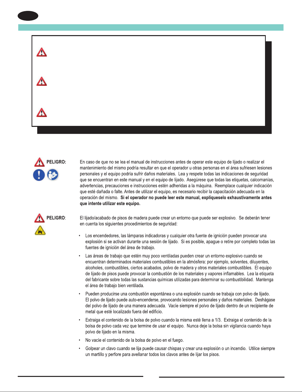
t ece to eet ee te ec hee oo th oceue
1 Loe the u to the oo
EN
2. Drive the adjusting screw in, to sand heavier on the left (the drive belt
side). Back the adjusting screw out, to sand heavier on the right (the
side opposite the drive belts). Test the setting on an even surface.
Make further adjustments if necessary.
3. Mark new pointer location on main frame.
Belt Tracking
NOTE: The sanding belt should run evenly on the face of the drum. For
this, the outer edge of the sanding belt must be .09 inches (2mm) out from
the end of the drum. This provides optimum transition between “passes”.
WARNING: Injury to the operator could occur if any
machine adjustments are made while the
motor is running. Do not attempt to make any
adjustments while the machine is plugged in or
running.
To adjust the belt tracking follow this procedure:
1 Locte the et tck ute ce ee ue 18A
2. Hold the belt tracking adjuster screw and loosen the locknut.
ee ue 18
3. Rotate the tracking adjuster screw counterclockwise to move the belt
in.
4. Rotate the tracking adjuster screw clockwise to move the belt out.
5. Test adjustment and tighten the locknut.
perating ontro
To increase the te o exte the ech o the coto oo th
procedure:
1 Looe the ockut o the coto o ee ue 1A
2 ce the coto o ute ee ue 1 In until the desired
reach is found.
3. Tighten the locknut.
To decrease the travel or reduce the reach on the grip control, follow this
procedure:
1 Looe the ockut o the coto o ee ue 20A
2 ce the coto o adjuster out until desired reach is found.
3. Tighten the locknut.
15
Figure 19
Figure 18
AA
AB
AA
AB
EN
Figure 20
A
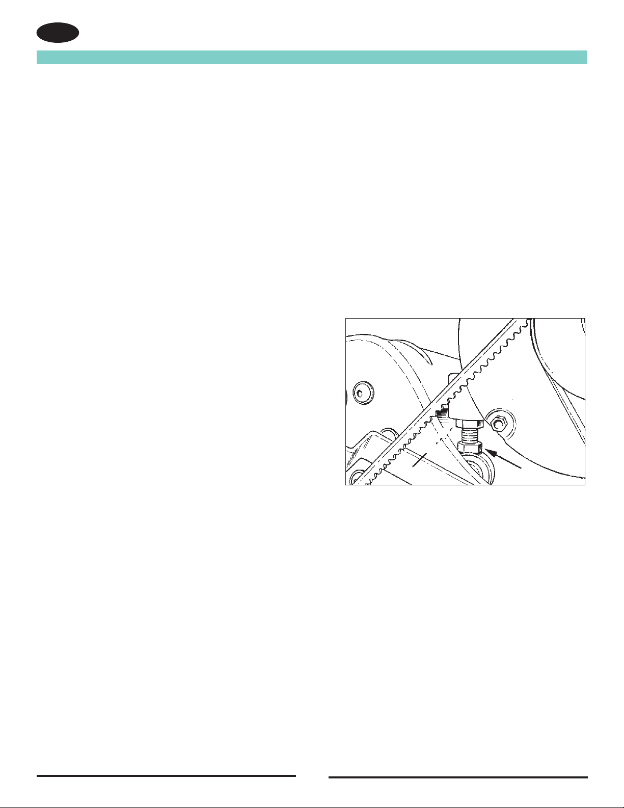
Figure 21
Routine Maintenance
u the utet ce ee ue 21 oe ute tu etoe
tension using quick release lever and check adjustment. Repeat this process
ece o oe teo the utet ce tue N
Bearings
eoc check the e o e o e cco to the
following schedule:
Guide rollers after 1st 650 hrs.
Idler pulley after 1st 1500 hrs.
Fan shaft after 1st 2500 hrs.
Tension roller after 1st 2500 hrs.
Arbor shaft after 1st 5000 hrs.
Motor shaft after 1st 5000 hrs.
Rollers
eoc check the ue oe the teo oe o e
16
EN
The following items need to be periodically inspected and maintained to keep your sander in good working condition.
Sanding hamer
eoc o out the che to eet e ccuuto o e hch cou teee th the eoce o the teo oe
NOTE: The tension lever should be in the run/tight abrasive position to blow out.
Wheels
eoc eoe the e o the tuck cte hee e c cue e o e uce
Dust Bag
Remove the dust bag from the machine and shake it thoroughly to remove the sanding dust from the dust bag. Turn the dust bag inside out and
machine wash in cold water to prevent pore blockage and loss of dust recovery.
Drive Belt
e et teo cto et hou ot eue utet eoc check the e et teo oe et teo chee he
o oce t the - o the et ouce ch o eecto
o cee et teo eee teo u uck eee ee ee ue 6

Troubleshooting
17
EN

Troubleshooting
18
EN
roem ause Action
Burning or glazing. Dull abrasive. Replace abrasive.
xcee eue ecee eue ett
16 e 1
oo e o e et e coe e
o cutt u e ece e
oo e o e et e coe e et
ucet eue cee eue ett
16 e 1
Waves on sanded surface. Debris on wheels. Remove and clean wheels.
Flat spot on tire(s). Replace tires.
htte k o e uce ee htte e eeto ee htte e eeto
(Close evenly spaced ripples) page 14. page 14.
Difficult to actuate tension release Debris interferes with mechanism Blow out sanding chamber.
lever. Remove and disassemble
mechanism. Clean out.
Worn sleeve bearing. Replace.
e ke Lucte th uct
Ae et hut eek o eee e heck o excee ece
High edges on drum. Contact an authorized dealer
or replace the drum.
Ae et ot tck xtee eece e-to-e ece e et
length of belt.
High edge on drum . Check several different abrasive
belts. Contact an authorized
dealer or replace the drum.
Abrasive belt tears along its Debris built-up on (top) tension Clean tension roller.
length. roller.

Contents
Instrucciones de seguridad para el operador...........................20-21
Introducción y especicaciones de la máquina............................22
Instrucciones de conexión eléctrica a 230V................................23
Cómo transportar la máquina...................................................24-25
Instalación de la máquina.......................................................26-27
Operación de la máquina.........................................................28-29
Cortes de lija y papel de lija............................................................29
Cómo evitar marcas de vibraciones y ondulaciones................30
Procedimientosde ajuste dela lijadora.....................................31-32
Mantenimiento de rutina...............................................................33
Resolución de problemas........................................................34-35
EA ESE MANUA
Este manua contiene inormacin importante acerca de uso a seguridad de a muina Si no ee e manua antes de utiiar su
muina American Sanders o de intentar reaiar os procedimientos de reparacin o mantenimiento de a misma usted o e resto
de persona podran surir esiones asimismo podran producirse daos a a muina o a otras propiedades Antes de utiiar a
máquina, es necesario recibir la capacitación adecuada en la operación de la misma. Si el operador de la máquina no sabe leer en
espao epuee e manua ehaustiamente antes de ue intente utiiara
Todas las indicaciones incluidas en este manual se ofrecen desde la posición del operador en la parte posterior de la máquina.
ADERENIA!
Lo oucto et e ete u cotee o uee cotee oucto uco ecooco o uo oeo coo e to
e o e o c e u ooc 6 Le e Aetec euto coo cute e cce eecto e ceto u oto
daños reproductivos. u uccoe cuo e to e o o cooe e eto oucto ue o cooue e eco
e u eeto o o e u eco e cceo co tee oc euto e e eteo o etec o
ucoe eecto e o oucto uco coteo o oeete coteo e o oucto uto e t u Es la responsabilidad
e coo cooce cu co to ee eetcoe eco co e uo e eto oucto e te etoo El Fabricante
e to eo e o o cooe oe euto eecco ue uee e e uo e o oucto e te etoo
19
ES
EIGR c te u ot eo uee et exueto u eoe eoe cue
muerte si las indicaciones de EIGR ue e ecuet e et u o e e u
e tuccoe e o o o e tee e cuet Le eete to ccoe
de EIGR ue e ecuet e e u e tuccoe e u
ADERENIA c te u ot eo uee et exueto u eoe eoe
indicaciones de ADERENIA ue e ecuet e et u o e e u e
tuccoe e o o o e tee e cuet Le eete to ccoe e
ADERENIA ue e ecuet e e u e tuccoe e u u
REAUIN c
L u u oto ee uee u o tee ccoe e REAUIN
ue e ecuet e u o e e u e tuccoe e o o o e
tee e cuet Le eete to ccoe e REAUIN que se
ecuet e e u e tuccoe e u
Instrucciones De Seguridad Para El Operador
ES
20
Other manuals for American SANDERS FloorCrafter
2
This manual suits for next models
7
Table of contents
Languages:
Other Amano Sander manuals

Amano
Amano American SANDERS FloorCrafter User manual

Amano
Amano American SANDERS EZ Sand - HDTR User manual

Amano
Amano American Sanders American 12 User manual

Amano
Amano American Sanders OSB-18 User manual

Amano
Amano American SANDERS FloorCrafter User manual

Amano
Amano American SANDERS EZ-8 User manual

Amano
Amano American Sanders American 8 User manual

Amano
Amano Pioneer Eclipse 225FP16TR User manual

Amano
Amano American Sanders Epoch HD User manual

Amano
Amano American Sanders OBS-18DC User manual


