Amano American SANDERS EZ-8 User manual

Drum Sander
EZ-8
Operator’s Manual

READ THIS BOOK
This book has important information for the use and safe operation of this machine. Failure to read this book prior to
operating or attempting any service or maintenance procedure to your American Sanders machine could result in injury
to you or to other personnel; damage to the machine or to other property could occur as well. You must have training in
the operation of this machine before using it. If your operator(s) cannot read this manual, have it explained fully before
attempting to operate this machine.
All directions given in this book are as seen from the operator’s position at the rear of the machine.
***This product is intended for commercial use only***
WARNING!
The Products sold with this Manual contain or may contain chemicals that are known to certain governments (such as the State of
California, as identied in its Proposition 65 Regulatory Warning Law) to cause cancer, birth defects or other reproductive harm. In
certain locations (including the State of California) purchasers of these Products that place them in service at an employment job site
or a publicly accessible space are required by regulation to make certain notices, warnings or disclosures regarding the chemicals that
are or may be contained in the Products at or about such work sites. It is the purchaser’s responsibility to know the content of, and to
comply with, any laws and regulations relating to the use of these Products in such environments. The Manufacturer disclaims any
responsibility to advise purchasers of any specic requirements that may be applicable to the use of the Products in such environments.
In this Operation Manual you will find three statements that you must read and observe to ensure safe operation of this
machine.
DANGER means: Severe bodily injury or death can occur to you or other personnel if the DANGER
statements found on this machine or in this Operation Manual are ignored or are not adhered to. Read
and observe all DANGER statements found in this Operation Manual and on your machine.
WARNING means: Injury can occur to you or to other personnel if the WARNING statements found on your
machine or in the Operation Manual are ignored or are not adhered to. Read and observe all WARNING
statements found in this Operation Manual and on your machine.
CAUTION means: Damage can occur to the machine or to other property if the CAUTION statements found
on your machine or in this Operation Manual are ignored or are not adhered to. Read and observe all
CAUTION statements found in this Operation Manual and on your machine.
Operator Safety Instructions
EN
Contents
Operator Safety Instructions......................................2-5
Introduction...................................................................6
Machine Specications.................................................6
Electrical Connection Instructions ................................7
Machine Transportation................................................8
Machine Setup.........................................................9-10
Operating Instructions ................................................ 11
Adjustment Procedures ..............................................12
Maintenance...............................................................12
Troubleshooting..........................................................13
Handle Assembly (07012A, 07058A, 07057A)......38-39
Handle Assembly (07060A)...................................40-41
Handle Assembly (07084A)...................................42-43
Handle Assembly (07240A)...................................44-45
Base Assembly......................................................46-47
Motor Assembly.....................................................48-49
Dust Control Assembly ..........................................50-51
Sanding Drum Assembly .......................................52-53
Wiring Diagram..........................................................54
Warranty.....................................................................55
Declaration of Conformity........................................... 58

3
A. Cigarette lighters, pilot lights and any other source of ignition can create an explosion when active during a sanding
session. All sources of ignition should be extinguished or removed entirely if possible from the work area.
B. Work areas that are poorly ventilated can create an explosive environment when certain combustible materials are in the
atmosphere, i.e., solvents, thinners, alcohol, fuels, certain nishes, wood dust and other combustible materials. Floor
sanding equipment can cause ammable material and vapors to burn. Read the manufacturer’s label on all chemicals
used to determine combustibility. Keep the work area well ventilated.
C. Spontaneous combustion or an explosion can occur when working with sanding dust. The sanding dust can self-ignite
and cause injury or damage. Sanding dust should be disposed of properly. Always empty the sanding dust into a metal
container that is located outside of any building(s).
D. Remove the contents of the dust bag when the bag is 1/3 full. Remove the contents of the dust bag each time you nish
using the equipment. Never leave a dust bag unattended with sanding dust in it.
E. Do not empty the contents of the dust bag into a re.
F. Hitting a nail while sanding can cause sparks and create an explosion or re. Always use a hammer and punch to
countersink all nails before sanding oors.
EN
DANGER: Failure to read the Owner’s Manual prior to operating or servicing your American Sanders machine could result in injury to
you or to other personnel; damage to the machine or to other property could occur as well. You must have training in the
operation of this machine before using it. If you or your operator(s) cannot read English, have this manual explained fully
before attempting to operate this machine.
DANGER:
DANGER:
DANGER:
DANGER:
WARNING::
WARNING::
WARNING::
WARNING::
Moving parts. Contact can cause severe injury.
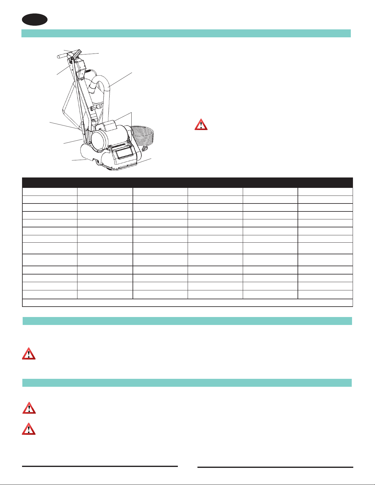
A. Disconnect machine from power source before accessing the sanding drum, drive belts, or fan chamber.
B. Do not operate unless drum cover, belt guard, and dust pipe are in place.
C. Never leave machine unattended while motor is running or connected to power source.
This sanding equipment requires a supply of electricity. Improper use could result in electrical
shock or re.
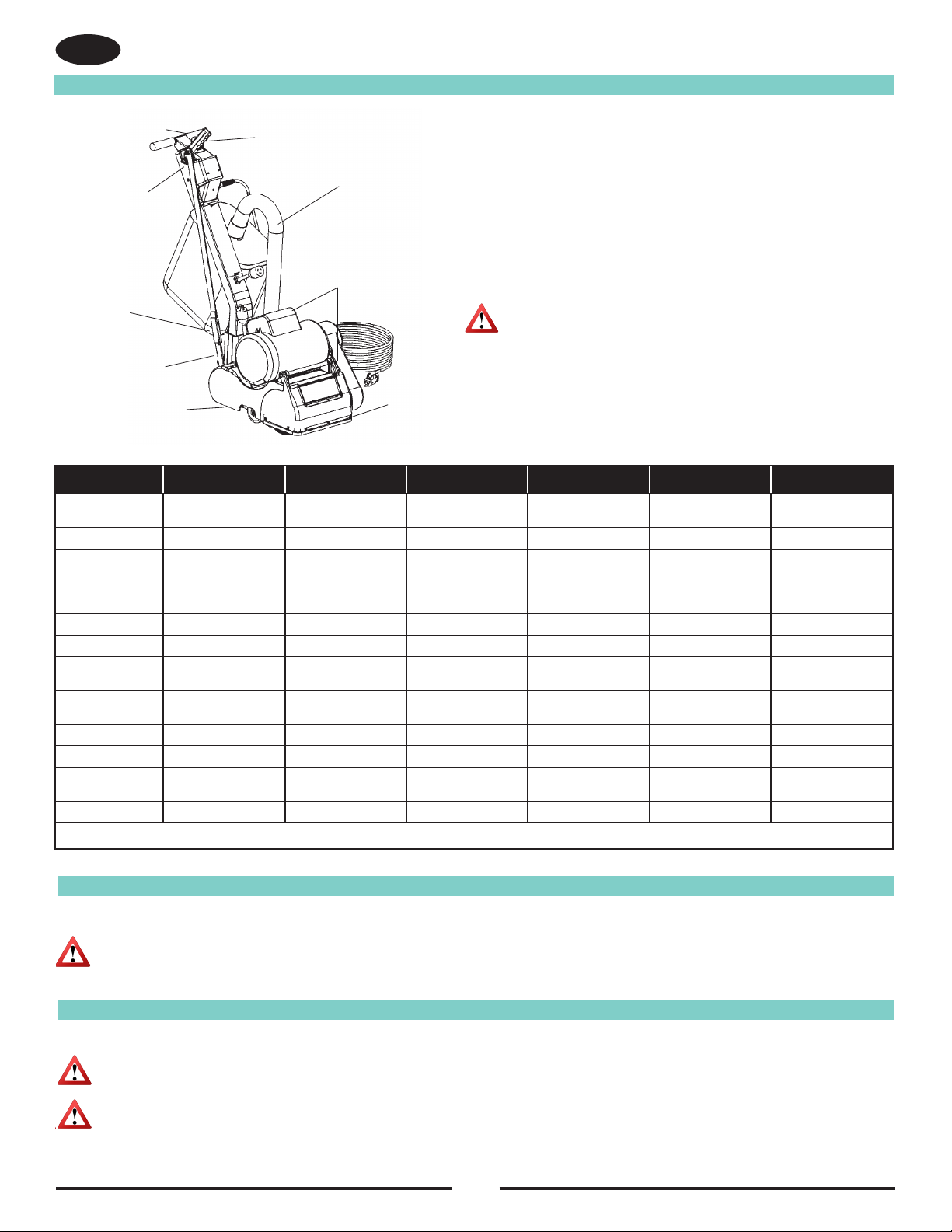
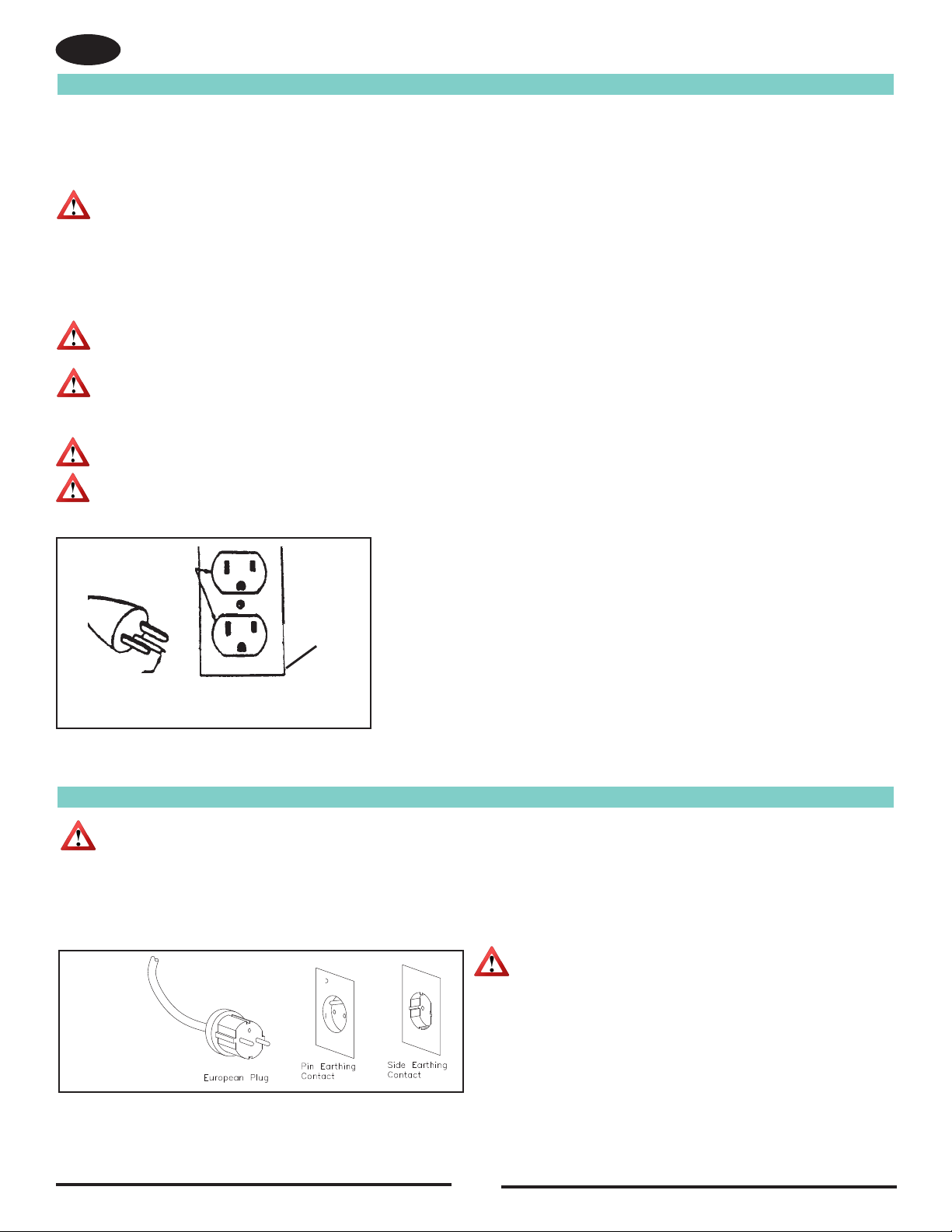
A. Connect only to an electrical source matching what is shown on the equipment nameplate.
B. Do not use this sanding equipment on an ungrounded electrical circuit. Consult an electrician if you suspect the circuit is
not properly grounded.
C. Do not use this sanding equipment with a damaged electrical cord. Inspect before each use.
D. Avoid striking the elelctrical cord with the abrasive. Always lift the electrical cord over the sanding equipment.
E. Do not use the electrical cord to move the sanding equipment.
F. Disconnect the electrical source before servicing this equipment.
Bodily injury could occur if power is applied to the equipment with the power switch already in the “ON” position. Always
check to assure that the power switch is in the “OFF” position before connecting power supply.
WARNING: Risk of explosion. Floor sanding can result in an explosive mixture of ne dust and air. Use oor sanding machine only in a
well-ventilated area free from any ame or match.
CAUTION: Maintenance and repairs performed by unauthorized personnel could result in damage or injury. Maintenance and repairs
performed by unauthorized personnel will void your warranty. Servicing of this unit must always be referred to an authorized
American Sanders distributor.
CAUTION: Use of this equipment to move other objects or to climb on could result in injury or damage. Do not use this equipment as a
step or furniture. Do not ride on this equipment.
CAUTION: Damage could occur to the equipment if not properly kept in a dry building for storage. Store the equipment in a dry building.
CAUTION: The equipment is heavy. When transporting the equipment, remove the motor. Get help to lift the equipment and motor.
CAUTION: Serious damage to the oor can occur if the sanding equipment is left running in one spot while the sanding drum is in
contact with the oor. To avoid damage to the oor, feather cut in at a normal sanding rate. Do not dwell while lowering or
raising the contact wheel. Always sand at a constant rate.

4
EN

5
EN

6
Introduction
EN
Operating
Control Lever
Control Switch
Control Link
Transport Handle
Dust Pipe
Locking Collar
Handle Latch
Level Adjustment Drum Cover
Extension Cords (120V)
Use only an approved extension cord with three conductors, a plug with three terminals, and a connector body with three holes.
WARNING:
If you use an extension cord, use an extension cord with minimum wire size 12 AWG. Do not use an extension cord longer than
50 feet. Do not join two extension cords.
CAUTION: Your equipment may be inappropriate on some
installations. Always consult with the ooring
manufacturer on the proper installation, preparation,
and nishing of their product. Determine suitability of
your equipment in preparing the product.
Model 07012A 07058A 07060A 07084A 07057A 07240A
Abrasive Size 8˝x 19˝sleeve
(20.3 x 48.2 cm) 8˝x 19˝sleeve
(20.3 x 48.2 cm)
Abrasive Rate 2830 ft/min 2830 ft/min 2360 ft/min 2360 ft/min 2830 ft/min 2360 ft/min
Drum Rate 1800 RPM 1800 RPM 1500 RPM 1500 RPM 1800 RPM 1500 RPM
Dust Control Rate 76 CFM 76 CFM 64 CFM 64 CFM 76 CFM 64 CFM
Drum Pressure 25 lbs (11.4 kg) 25 lbs (11.4 kg) 25 lbs (11.4 kg) 25 lbs (11.4 kg) 25 lbs (11.4 kg) 25 lbs (11.4 kg)
Leveling Controls Externally Adjustable Externally Adjustable Externally Adjustable Externally Adjustable Externally Adjustable Externally Adjustable
Operating Controls Lever Operated Lever Operated Lever Operated Lever Operated Lever Operated Lever Operated
Motor 1½ HPTEFC
Thermally Protected 1½ HPTEFC
Thermally Protected
Power Cable 40΄ (12.1m) 12 Gauge
Abrasive Resistant
40΄ (12.1m) 12 Gauge
Abrasive Resistant
50΄ (15.2m) 12 Gauge
Abrasive Resistant
40΄ (12.1m) 12 Gauge
Abrasive Resistant
40΄ (12.1m) 12 Gauge
Abrasive Resistant
40΄ (12.1m) 12 Gauge
Abrasive Resistant
Voltage Frequency 115 / 60 115 / 60 240 / 50 240 / 50 115 / 60 240 / 50
Amperage 12 12 6 6 12 6
Dimensions (in)* 21½˝ x 16˝ x 35½˝
(54.6 x 40.6 x 90.2 cm) 21½˝ x 16˝ x 35½˝
(54.6 x 40.6 x 90.2 cm)
Weight (lbs) * 125 (57 kg) 125 (57 kg) 125 (57 kg) 125 (57 kg) 125 (57 kg) 125 (57 kg)
* Shipping Value
Extension Cords (230V)
Use only an approved extension cord with two main conductors and one earthing conductor.
WARNING: If you use an extension cord, use an extension cord with minimum wire size 10 AWG. Do not use an extension cord longer
than 50 ft. Do not join two extension cords.
WARNING: Do not cut, remove, or break the ground terminal. Do not try to fit a three-terminal plug into a receptacle or connector body
that does not fit the plug. If the receptacle or connector body does not fit the plug, see your Authorized person to make
the connection.

7
EN
Instructions for connection to the power supply and the electrical ground.
This product must be grounded. If it should malfunction or breakdown, grounding provides a path of least resistance for electric current to reduce
the risk of electrical shock. This product is equipped with a cord having an equipment-grounding conductor and grounding plug. The plug must be
inserted into an appropriate oulet that is properly installed and grounded in accordance with all local codes and ordinances.
WARNING: Improper connection of the equipment-grounding conductor can result in a risk of electric shock. Check with qualied electrician
or service person if you are in doubt as to whether the outlet is properly grounded. Do not
modify the plug provided with the
product – if it will not t the outlet, have a proper outlet installed by a
qualied electrician.
This product is for use on a nominal 120 volt circuit and has a grounding attachment plug that looks like the plug illustrated in gure 12. Make sure
that the product is connected to an outlet having the same conguration as the plug. No adapter should be used with this product. Always connect
the machine to a dedicated 20 amp electrical line to prevent nuisance breaker tripping and line overload due to other devices.
WARNING: To prevent possible electric shock, protect the machine from rain. Keep the machine in a dry building.
WARNING: To prevent possible electric shock, always use a 3-wire electrical system connected to the electrical ground. For maximum
protection against electrical shock, use a circuit that is protected by a ground fault circuit interupter. Consult your electrical
contractor.
WARNING: Do not cut, remove or break the ground pin. If the outlet does not t the plug, consult your electrical contractor.
WARNING: Have worn, cut or damaged cords replaced by an authorized service person.
Electrical Connection Instructions (120V)
Figure 12
Grounded
Outlet
Grounding
Pin
(United States, Mexico and Canada)
Grounded
Outlet
Box
Electrical Connection Instructions (230V)
CAUTION: This machine will operate only on the AC frequency and electrical voltage shown on the nameplate. Make sure you have the
correct frequency and voltage before connecting the power cord to an outlet.
This machine must be connected to the electrical ground to protect the operator from electric shock. The machine has a power cord with two
main conductors and one earthing conductor. Connect the plug to the type of receptacle shown in figure 5. The green and yellow conductor cord
is the ground wire. Never connect this wire to any terminal other than the ground terminal.
WARNING: Always use this machine with an AC three-
conductor electrical system connected to the
electrical ground. Replace any worn, cut, or
damaged cords. Replace any damaged plugs,
receptacles, or connector bodies. Do not move
the machine over an electrical cord. Always lift
the cord over the machine.
Figure 5

8
Machine Transportation
EN
Figure 1
Figure 2
Figure 3
WARNING: Machine is heavy – 95 lbs (43 kg)
To avoid injury or damage, grasp transport
handlesrmly;useproperliftingtechnique.
Figure 4

9
Machine Set-up
EN
Figure 5
Figure 6
Figure 8
Figure 7

10
Machine Setup
EN
This sanding machine is designed to be operated with a remote vacuum dust
collection system or with the included dust bag.
Preparing Remote Vacuum Dust Collection Systems
To prepare the machine for remote vacuum dust collection systems that have a
2 (5 cm) hose end, follow this procedure:
1. Install 2 (5 cm) hose end (gure 9, A) directly over the exhaust tube
(gure 9, B).
2. The exhaust tube can be rotated for optimum convenience.
To prepare the machine for remote vacuum dust collection systems that have a
1 ½(3.8 cm) hose end, follow this procedure:
1.
Install the 2
(5 cm)
x 1½
(3.8 cm)
hose end adapter (Part No. 30563A)
(gure 9, C)
over the exhaust tube (gure 9, B).
2. Insert 1 ½ (3.8 cm) hose end (gure 9, D) into the adapter (gure 9, C).
NOTE: Start the remote vacuum collection system before operation.
Preparing to use the included dust bag
To prepare the machine for use with the included dust bag (Part No. 53544B),
follow this procedure:
1. Install the dust bag by pressing the end onto the exhaust tube
until the ring locks into the groove (gure 10). This is best done
by pressing on the back of the bag opening with the palm of your hand.
2. The exhaust tube can be rotated for optimum convenience.
3. To remove the dust bag from the exhaust tube, pry up the end
of the bag opening to partially release the internal rib from the
groove, then pull.
4. To empty the dust bag, unzip the disposal ap and force contents
out by inverting the bag.
NOTE: For best results, empty frequently. Follow all warnings posted
in this
manual and on the dust bag.
Figure 9
Figure 10
Install the dust bag by
pressing the end onto the
exhaust tube until the ring
locks into the groove.
1.5(3.8 cm)
Hose from vacuum
system (not included)
B
C
Exhaust Tube
AD
2 (5 cm)
Hose from
vacuum
system (not
included)
(30563A)
2 (5 cm) Tube x 1.5(3.8 cm)
hose adapter

11
Operating Instructions
EN
Figure 11
1
3
2
4

12
Adjustment Procedures
Routine Maintenance
EN
Leveling
To adjust the machine leveling follow this procedure:
1. Locate the leveling screw. See gure 12.
2. Tighten the screw (compress the leveling spring) to sand heavier on drive
belt side of sanding drum.
3. Loosen the leveling screw (relax the leveling spring) to sand heavier on the side
opposite the drive belts.
Condition - Pad creates ridges on both edges or a “hop” is experienced: Rotate
both adjusting screws equal amounts clockwise. Tighten locknuts and test on a
piece of plywood. Repeat procedure until condition is corrected. We recommend you
not exceed 1/8 rotation for each attempt.
Condition - Pad creates a ridge on the tip of the pad: Rotate both adjusting screws
counter clockwise, tighten locknuts and test. Repeat procedure until condition is
corrected. Use only 1/8 rotation for each attempt.
Condition - Pad creates a ridge on only one side of the pad: Either rotate the
adjusting screw of the side effected clockwise or rotate the adjusting screw opposite
counterclockwise, depending on whether the ridge terminates beyond the tip of the
pad or prior to it. If it is prior to the tip, adjust the side effected, otherwise adjust the
opposite side.
Figure 12
Dust Shoe
To adjust the dust shoe follow this procedure:
1. Disconnect machine from power supply.
2. Loosen the four screws fastening the dust shoe to the chassis.
3. Adjust the dust shoe towards the drum to improve recovery of ne particles.
4. Adjust the dust shoe away from the drum to improve recovery of coarse particles.
5. Align the dust shoe with the drum and tighten screws. See gure 12b. Figure 12b
Sanding Chamber
Periodically blow out the sanding chamber to prevent large accumulations of debris which could interfere with the performance of the dust
recovery system.
Wheels
Periodically remove the debris from the truck and caster wheels. Debris can cause waves on a sanded surface.
Dust Bag
Remove the dust bag from the machine and shake it thoroughly to remove the sanding dust from the dust bag. Turn the dust bag inside out and
machine wash in cold water to prevent pore blockage and loss of dust recovery.
Drive Belt
Periodically check the drive belts for broken cogs or frayed edges. Frayed edges may indicate poor tracking. Realign affected belt.
Bearings
Periodically check the bearings for wear or damage according to the following schedule.
Arbor shaft: Re-lubricate every 150 hrs. w/.10 oz. of a NLGI grade 2, -300F (-34.4C) to 2500F (121.1C), 58-75 SUS at 2100 F (98.8C), grease
lubricant.
Motor shaft: After 1st 5000 hrs.
Fan shaft : After rst 1500 hrs.
CAUTION: Failure to perform maintenance at recommended intervals may void warranty.
CAUTION:
Maintenance and repairs performed by unauthorized personnel could result in damage or injury. Maintenance and repairs performed
by unauthorized personnel will void your warranty. Failure to perform maintenance at recommended intervals may void warranty.

13
EN
Troubleshooting

14
Contents
Instrucciones de seguridad para el operador.............................13
Introducción................................................................15
Instrucciones de conexión eléctrica ..............................................16
Instalación de la máquina............................................................17
Operacióndelamáquina..........................................................18-19
Mantenimiento de rutina...............................................................20
LEA ESTE MANUAL
Este manual contiene información importante acerca del uso y la seguridad de la máquina. Si no lee el manual antes de utilizar su
máquina American Sanders o de intentar realizar los procedimientos de reparación o mantenimiento de la misma, usted o el resto
delpersonalpodríansufrirlesiones;asimismo,podríanproducirsedañosalamáquinaoaotraspropiedades.Antesdeutilizarla
máquina, es necesario recibir la capacitación adecuada en la operación de la misma. Si el operador de la máquina no sabe leer en
español,explíqueleelmanualexhaustivamenteantesdequeintenteutilizarla.
Todas las indicaciones incluidas en este manual se ofrecen desde la posición del operador en la parte posterior de la máquina.
ADVERTENCIA!
Los Productos a la venta en este Manual contienen, o pueden contener, productos químicos reconocidos por algunos gobiernos (como el Estado
de California, según lo indica en su Proposición 65, Ley de Advertencia Regulatoria) como causantes de cáncer, defectos de nacimiento u otros
daños reproductivos. En algunas jurisdicciones (incluido el Estado de California), los compradores de estos Productos que los coloquen en servicio
en un emplazamiento laboral o en un espacio de acceso público tienen la obligación regulatoria de realizar determinados avisos, advertencias o
divulgaciones respecto de los productos químicos contenidos o posiblemente contenidos en los Productos utilizados en tal lugar. Es la responsabilidad
del comprador conocer y cumplir con todas las leyes y reglamentaciones relacionadas con el uso de estos Productos en tales entornos. El Fabricante
niega toda responsabilidad de informar a los compradores sobre requisitos especícos que pueden regir el uso de los Productos en tales entornos.
ES
Contents
Instrucciones de seguridad para el operador..........................15-16
Introducción....................................................................17
Instrucciones de conexión eléctrica ..............................................18
Cómo transportar la máquina ......................................................19
Instalación de la máquina.......................................................20-21
Operación de la máquina..............................................................22
Procedimientos de ajuste de la lijadora.........................................23
Mantenimiento de rutina...............................................................23
Resolución de problemas.............................................................24

15
PELIGRO signica: Usted u otras personas pueden estar expuestos a sufrir lesiones personales, inclusive la
muerte si las indicaciones de PELIGRO que se encuentran en esta máquina o en el manual
de instrucciones se ignoran o no se tienen en cuenta. Lea y respete todas las indicaciones
de PELIGRO que se encuentran en el manual de instrucciones y en la máquina.
ADVERTENCIA signica: Usted u otras personas pueden estar expuestos a sufrir lesiones personales, si las
indicaciones de ADVERTENCIA que se encuentran en esta máquina o en el manual de
instrucciones se ignoran o no se tienen en cuenta. Lea y respete todas las indicaciones de
ADVERTENCIA que se encuentran en el manual de instrucciones y en su máquina.
PRECAUCIÓN signica:
La máquina u otros bienes pueden sufrir daños materiales si las indicaciones de PRECAUCIÓN
que se encuentran en la máquina o en el manual de instrucciones se ignoran o no se
tienen en cuenta. Lea y respete todas las indicaciones de PRECAUCIÓN que se
encuentran en el manual de instrucciones y en la máquina.
Instrucciones De Seguridad Para El Operador
ES

16
ES
PELIGRO: Piezas móviles. El contacto puede causar lesiones graves.
A.
B.
C.
Desconecte la máquina de la fuente de alimentación antes de acceder al tambor de lijado, las correas de
transmisión o la cámara del ventilador.
No la opere sin la cubierta del tambor, el protector de la correa y el conducto de polvo en su lugar.
Nunca deje la máquina conectada a la fuente de alimentación o con el motor en funcionamiento sin supervisión.

17
Cables de extensión (120 V)
Utilice únicamente un cable de extensión autorizado con tres conductores, un enchufe con tres terminales y un cuerpo del conector con tres
oricios.
ADVERTENCIA: Si va a utilizar un cable de extensión, use uno de un calibre mínimo de 12 AWG. No use un cable de extensión de más de
50 pies. No una dos cables de extensión.
Cables de extensión (230 V)
Utilice únicamente un cable de extensión aprobado con dos conductores principales y uno de puesta a tierra.
ADVERTENCIA : Si va a utilizar un cable de extensión, use uno de un calibre mínimo de 1,50 mm2. No use un cable de extensión de más
de 15 metros. No una dos cables de extensión.
ADVERTENCIA: No corte, quite o rompa el terminal de conexión a tierra. No intente conectar un enchufe de tres terminales en un
receptáculo o cuerpo conector en el que no encaje. Si el enchufe no encaja en el receptáculo o cuerpo conector, consulte con una persona
autorizada para realizar la conexión.
Modelo 07012A 07058A 07060A 07084A 07057A
Tamañodeabrasive(cm) 20.3 x 48.2 la manga 20.3 x 48.2 la manga 20.3 x 48.2 la manga 20.3 x 48.2 la manga 20.3 x 48.2 1/2 la manga
Tasa de abrasivo 2830 pies/min 2830 pies/min 2360 pies/min 2360 pies/min 2830 pies/min
Tasa del tambor 1800 RPM 1800 RPM 1500 RPM 1500 RPM 1800 RPM
Tasa de control del polvo 76 CFM 76 CFM 64 CFM 64 CFM 76 CFM
Presión del tambor 11.4 kg 11.4 kg 11.4 kg 11.4 kg 11.4 kg
Controles de nivelación Adjustables externamente Adjustables externamente Adjustables externamente Adjustables externamente Adjustables externamente
Controles operativos Mango ajustable Mango ajustable Mango ajustable Mango ajustable Mango ajustable
Motor 1½ HPTEFC
protegidos térmicamente 1½ HPTEFC
protegidos térmicamente
Cable de alimentación 40’ 12 Gauge
resistente a la abrasión 40’ 12 Gauge
resistente a la abrasión 50’ 12 Gauge
resistente a la abrasión 40’ 12 Gauge
resistente a la abrasión
Tensión (V)
/ Frecuencia (Hz)
115 / 60 115 / 60 240 / 50 240 / 50 115 / 60
Corriente (A) 12 12 6 6 12
Dimensiones (cm)* 54.6 X 40.6 X 90.2 54.6 X 40.6 X 90.2 54.6 X 40.6 X 90.2 54.6 X 40.6 X 90.2 54.6 X 40.6 X 90.2
Weight (kg)* 57 57 57 57 57
* Valor de envoi
Palanca de control de
funcionamientor
Interruptor
de control
Enlace de control
Manija de transporte
Collarín de cierre
Collarín de cierre
Tubo para aspiración
de polvo
Ajuste del nivel Tapa del tambor
PRECAUCIÓN: Su equipo puede ser inapropiado en
algunas instalaciones. Siempre consulte
con el fabricante del piso sobre la correcta
instalación, preparación, y acabado de su
producto. Determine la idoneidad de su
equipo para preparar el producto.
.
Introducción
ES

18
Instruccionesparalaconexiónalafuentedealimentaciónyatierra.
Este producto se debe conectar a tierra. En caso de mal funcionamiento o averías, la conexión a tierra proporciona una vía de menor resistencia
para la corriente eléctrica a n de reducir el riesgo de choques eléctricos. Este producto está equipado con un cable que tiene un conductor que
pone el equipo a tierra y un enchufe de conexión a tierra. El enchufe se debe insertar en un tomacorriente adecuado que esté instalado debidamen-
te y puesto a tierra de conformidad con todos los códigos y las normas locales.
ADVERTENCIA : La conexión incorrecta del conductor de puesta a tierra del equipo puede resultar en riesgos de choque eléctrico.
Consulte con un electricista o un técnico de servicio calicados si tiene alguna duda con respecto a si el tomacorriente está puesto a tierra adecua-
damente. No
modique el enchufe suministrado con la máquina. Si no encaja en el tomacorriente, contacte a un electricista calicado para que instale un a
tomacorriente adecuado.
Este producto está diseñado para utilizarse en un circuito de potencia nominal de 120 voltios, y tiene un enchufe de conexión a tierra semejante al
enchufe ilustrado en la Fig. 12. Asegúrese de que el producto esté conectado a un tomacorriente que tenga la misma conguración que el enchu-
fe. No se deben utilizar adaptadores con este producto. Siempre conecte la máquina a una línea eléctrica dedicada de 20 amperios para evitar el
accionamiento del disyuntor y la sobrecarga de la línea debido a otros dispositivos.
ADVERTENCIA : Para evitar el riesgo de choques eléctricos, proteja la máquina de la lluvia. Guárdela en un lugar seco.
ADVERTENCIA : Para evitar el riesgo de choques eléctricos, siempre use un sistema eléctrico de tres conductores con conexión a tie-
rra. Para una protección óptima contra choques eléctricos, utilice un circuito protegido por un interruptor de falla a tierra. Consulte con su contratista
electricista.
ADVERTENCIA : No corte, quite o rompa la clavija de conexión a tierra. Si el enchufe no encaja en el tomacorriente, consulte con su
contratista electricista.
ADVERTENCIA : Los cables desgastados, cortados o dañados los debe remplazar un técnico de servicio autorizado.
Instrucciones para la la conexión eléctrica (120 V)
Instrucciones para la la conexión eléctrica (230V)
PRECAUCIÓN: Esta máquina funciona únicamente con la frecuencia de CA y el voltaje que se indican en la placa de identificación.
Asegúrese de que la frecuencia y el voltaje sean adecuados antes de conectar el cable de alimentaciónal tomacorriente.
La máquina se debe conectar tierra para proteger al operador de choques eléctricos. La máquina tiene un cable de alimentación con dos
conductores principales y uno de puesta a tierra. Conecte el enchufe en el tipo de receptáculo que se muestra en la figura 5. El cable conductor
verde y amarillo es el cable de conexión a tierra. Nunca conecte este cable a otro terminal que no sea el de conexión a tierra.
ADVERTENCIA : Siempre use esta máquina con un sistema
eléctrico de CA de tres conductores conectado a tierra. Remplace
los cables que estén desgastados, cortados o dañados. Remplace
los enchufes, los receptáculos o los cuerpos conectores que estén
dañados. No pase la máquina por encima del cable eléctrico.
Siempre levante el cable por encima de la máquina.
Figura 5
ES
Figura 12
Tomacorriente
(Estados Unidos, México y Canadá)
Toma
corriente
conectado
a tierra
Clavija de conexión
a tierra

19
Cómo transportar la máquina
ES
Figura 1
Figura 2
Figura 3
Figura 4

20
Instalación de la máquina
ES
Para instalar su máquina siga este procedimiento:
1. Familiarícese con la máquina y lea todas las indicaciones de
peligro, advertencia y precaución. Asegúrese de que todos
los operadores de la máquina hayan leído este manual de
instrucciones. Si ellos no pueden leer este manual, explíqueles
el mismo por completo antes de permitirles operar la lijadora.
2. Instale la manija y je los seguros. Consulte la gura 6.
3. Inserte el enlace de control en la ranura y deslice el collarín
hasta la clavija. Levante el tambor de lijado con la palanca de
control. Consulte las guras 5 & 6.
4. Instale el tubo de aspiración de polvo.
5. Conecte el cable exible de la manija al cable del motor.
Alinee la clavija de tierra, insértela y tuérzala. Consulte la gura 7.
6. Para instalar el abrasivo sobre el tambor de lijado equipado con
abrazadera de papel: aoje los tornillos de la abrazadera de
papel con una moneda. No retire los tornillos ni la abrazadera
del tambor de lijado. Inserte un borde del abrasivo debajo de la
abrazadera de papel. Rote el tambor de lijado para envolver el
abrasivo alrededor del tambor. Inserte otro borde del abrasivo
debajo de la abrazadera de papel. Centre el abrasivo y ajuste
cualquier holgura del abrasivo. Ajuste los tornillos en la
abrazadera
de papel. Cierre la cubierta del tambor. Consulte la
gura 8.Para instalar el abrasivo sobre el tambor de lijado
equipado
para el abrasivo de manguito: deslice el abrasivo so-
bre el tambor, centre el abrasivo, y cierre la cubierta del tambor.
This manual suits for next models
6
Table of contents
Languages:
Other Amano Sander manuals

Amano
Amano American Sanders American 8 User manual

Amano
Amano Pioneer Eclipse PE225FP User manual

Amano
Amano American Sanders 3DS User manual

Amano
Amano Pioneer Eclipse 225FP16TR User manual

Amano
Amano American SANDERS FloorCrafter User manual

Amano
Amano American SANDERS FloorCrafter User manual

Amano
Amano American Sanders OBS-18DC User manual

Amano
Amano American SANDERS FloorCrafter User manual

Amano
Amano American Sanders American 12 User manual

Amano
Amano American Sanders OSB-18 User manual