AMBIC EasiDoser User manual


Ambic Equipment Ltd –EasiDoser™ Operating Notes
-2- ADE7500 v1.3 (16/03/18)
Contents
Introduction................................................................................................................................3
Safety..........................................................................................................................................3
Specifications.............................................................................................................................3
Installation (refer to Fig.1, 2, 4) .................................................................................................4
Layout......................................................................................................................................4
Electrical Connections...............................................................................................................5
Opto Isolator Connection ..........................................................................................................6
Initial Set Up –Electrical Connections & Calibration/Programming Functions.....................7
EasiDoser™ – Power Up/Down & Normal Run Displays......................................................7
EasiDoser™ – Basic Menu Option Displays.............................................................................8
EasiDoser™ – Set Two Pump Operations ............................................................................8
EasiDoser™ – Changing Pin Code......................................................................................10
EasiDoser™ – Pump 1 Calibration Method.........................................................................12
EasiDoser™ – Pump 2 Calibration Method.........................................................................12
EasiDoser™ – Pump Statistics............................................................................................13
EasiDoser™ – Warning Displays.........................................................................................13
Initial Set Up –Priming & Setting up the system ready to use .............................................14
Operation ..............................................................................................................................14
Maintenance..........................................................................................................................14

Ambic Equipment Ltd –EasiDoser™ Operating Notes
-3- ADE7500 v1.3 (16/03/18)
Introduction
The EasiDoser™is an advanced microprocessor-controlled dosing system for dispensing a precise
amount of chemical. The dispenser features an electronic circuit board with an LCD display. Programming
is set using the keypad on the front of the unit and has a special pump ‘Lock-out’ that will prevent
consecutive dispensing. The EasiDoser™also has a “delay pump start”feature and a direct mode (Relay
Mode) which allows for a timed signal from a microprocessor to control the pump run timing.
The EasiDoser™is offered in various configurations: one, two or three low volume pumps, or an industrial
pump version.
Depending how the unit is programmed, the EasiDoser™ will activate when the circuit receives a 12-230V
AC or 12-24V DC machine signal through the Opto Isolator, or closed contact to one of the trigger inputs.
Also, it can be used for manual dosing and this is activated by pressing a button on the keypad.
Safety
The EasiDoser™Chemical Dosing System is designed exclusively for dosing chemicals by function of
Time, Time and Speed or Direct (Relay) mode in unrestricted pressure tanks. Any application outside the
use described in this operating manual will be taken to be not in accordance with the intended purpose.
The manufacturer/supplier will not be held responsible for any losses arising as a result of such use. The
user will take full responsibility for use.
USE IN ACCORDANCE WITH THE INTENDED PURPOSE ALSO INCLUDES COMPLYING WITH THE
OPERATING MANUAL AND THE CONDITIONS FOR INSPECTION AND MAINTENANCE.
Specifications
Power Source 230V –Pumping unit • 220-240V AC 50Hz
–Fuses • T1.0A
115V –Pumping unit • 110-120V AC 60Hz
–Fuses • T2.0A
Machine Signal - • 12 –230V AC
• 12 –24V DC
• Contact switch
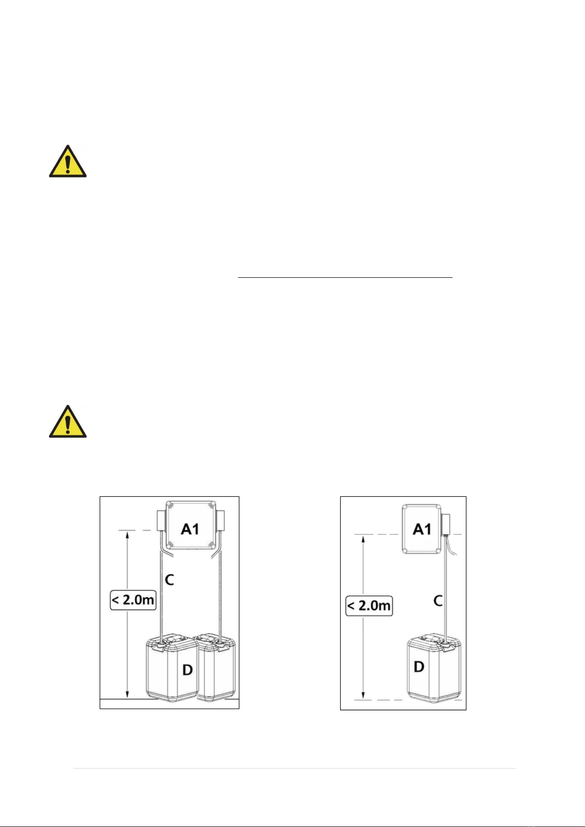
Maximum Length of Distribution Tubing • 10 Metres
Operating Temperature • 5 –40 °C
Float Switch • Normally Open type

Ambic Equipment Ltd –EasiDoser™ Operating Notes
-4- ADE7500 v1.3 (16/03/18)
Installation (refer to Fig.1, 2, 4)
Electrical Installation - should ideally be carried out by a Qualified Electrician –The 3-core power supply
cord MUST remain accessible when the unit has been installed and MUST be connected to Earth. THIS
ELECTRICAL SUPPLY SHOULD BE PROTECTED BY AN APPROPRIATE EARTH LEAKAGE CIRCUIT
BREAKER.
CAUTION: To avoid severe or fatal shock, always disconnect main power when
servicing the unit.
Chemical –is sucked up from a chemical container by peristaltic pump(s). The enclosure housing the
EasiDoser™pump(s) is rated at IP44 (IEC 60529); the power unit (A) must, therefore, be positioned in a
dry location and close to a 220-240V AC power socket (Maximum Power consumed: 50W).
The enclosure (A1) should be positioned no more than 2 metres vertically above the floor and no more
than 3 metres distant from the chemical container(s). Use the drilling template to mark out screw positions
and fix the enclosure to a suitable flat surface, using the screws and plastic plugs supplied.
The chemical container(s) (D) should be placed securely on the floor and the inlet tube(s) (C) from the
pump enclosure should be connected to the inlet nipple(s) of the peristaltic pump(s) –each PVC inlet tube
should be measured for correct length (cutting the excess tube) and warmed before being pushed over the
peristaltic pump spigot and secured with the stainless steel hose clips. Make sure that clips are fitted so
that the barb of the fitting on the pump is central in the clip and do NOT over tighten the clip (you risk
breaking the plastic nipple). Drop the filter end of the inlet tube(s) into the chemical container(s) –
ALWAYS ENSURE that each inlet tube has a FILTER FITTED.
CAUTION: Wear protective clothing and eyewear when dispensing chemicals or any
other materials. Observe safety handling instructions (MSDS) of chemical manufacturers.
Layout
Fig. 1 - General Layout for Twin EasiDoser™Fig. 2 –General layout for a Single EasiDoser™

Ambic Equipment Ltd –EasiDoser™ Operating Notes
-5- ADE7500 v1.3 (16/03/18)
Electrical Connections
Unscrew the 2 screws in the corners of the
enclosure. Hinge lid open to reveal the PCB
inside lid.
Terminal blocks may be pulled off from the
PCB to allow easy connection of wires into
Screw Terminals.
Positions of wires are noted LEFT >> RIGHT
(see PCB Layout diagram below right)
MAINS = 220-240V AC
L = LIVE –Brown wire
E = EARTH –Green/Yellow wire
N = NEUTRAL –Blue wire
P1 = Pump 1 –Pink wire +
Grey wire -
P2 = Pump 2 –Pink wire +
Grey wire -
P3 = Pump 3 –Pink wire +
Grey wire -
Opto 4 = Signal wire Pump 1
12-230V AC via Opto Isolator
12-24V DC via Opto Isolator
Close contact direct input
Opto 5 = Signal wire Pump 2
12-230V AC via Opto Isolator
12-24V DC via Opto Isolator
Close contact direct input
Opto 3 = Signal wire Pump 3
12-230V AC via Opto Isolator
12-24V DC via Opto Isolator
Close contact direct input
FS1 & 2 = Float Switch 1 & 2
–Brown wire
–White wire
WARNING!
DISCONNECT UNIT COMPLETELY
FROM MAINS POWER BEFORE OPENING
LID.
Figure 3 –EasiDoser™Switch Operations
Figure 4 –EasiDoser™Electrical Connections
ON/OFF SWITCH
PUSH > ON
PUSH > OFF
PUMP 2 ON 2 PUMP SYSTEM
PUMP 3 ON 3 PUMP SYSTEM
PUMP 1
MENU
NAVIGATE
BUTTON
MENU “CONFIRM” BUTTON
PUMP 2 ON 3 PUMP SYSTEM
FS1
FS2
P1
P2
P3 if fitted
Opto 4
Opto 5
Opto 3
LEN
Mains

Ambic Equipment Ltd –EasiDoser™ Operating Notes
-6- ADE7500 v1.3 (16/03/18)
Opto Isolator Connection
For volts-free signal (switch) there is no requirement for Opto Isolator and the switch can be connected
directly to the inputs marked on the PCB as Opto 4 & Opto 5. For a 12-24V DC signal or 24-230V AC
signal unit, the signal MUST be connected via the Opto Isolator(s) supplied with the unit.
Opto
Isolator 2
Opto
Isolator 1
Figure 5 –Opto Isolator
Opto Isolator 1
Brown & Blue –connect to 12-24V DC or 24-230V AC signal
Red & Black –connect to Opto 4
Opto Isolator 2
Brown & Blue –connect to 12-24V DC or 24-230V AC signal
Red & Black –connect to Opto 5
Opto Isolator 3
Brown & Blue –connect to 12-24V DC or 24-230V AC signal
Red & Black –connect to Opto 3
Figure 6 –Opto Isolator position on PCB
The Red & Black wires should be connected to Opto 4 or Opto 5.
Opto 4 triggers the left hand pump and Opto 5 triggers the right
hand pump on a 2 pump system.
On a 3 pump system, Opto 3 triggers pump 3.
Opto
Isolator 3
Opto 3
Opto 4
Opto 5
Red
Black
Opto 5
Opto 4
Red
Black
Red
Black

Ambic Equipment Ltd –EasiDoser™ Operating Notes
-7- ADE7500 v1.3 (16/03/18)
Initial Set Up –Electrical Connections & Calibration/Programming
Functions
The EasiDoser™control box is connected up as shown in Figure. 4 on page 5. It includes many useful
safety and programmable features, for which the following instructions should be read through carefully to
ensure efficient operation of the unit.
EasiDoser™ – Power Up/Down & Normal Run Displays
Action
Display
Comment /Action
Switch Mains Power ON
Press on/off Button
Display Number 1
Displays for 5 seconds.
Automatically changes to NEXT display.
Display Number 2
Pump(s) NOT running. No trigger signal
applied or start dose button pressed.
Press On/Off Button
(when switching off the unit/
leaving on standby)
Display Number 3
Displays for 2 seconds, then screen blank.
Unit in “Standby / Off” mode.
Press On/Off Button
Display Number 1
Displays for 5 seconds.
Automatically changes to display 2.
Disconnect from
Mains Power
Display Number 4
Unit completely “Off”
Warning “Bleep” before screen blank.
The EasiDoser™ is supplied as either a single, twin or three pump system and can be set to run up to the
maximum number of pumps fitted. This is controlled by the user-programmable settings selected from the
menus detailed below.
Pumps are driven by low voltage DC motors and their time or speed of operation is controlled by the voltage
applied to each pump motor in order to ensure that the pumps are dispensing the correct quantity of
chemical(s).
Ambic Equipment
EasiDoser V1.1
Waiting
for Trigger ←0→
EasiDoser
Power Down
Ambic Equipment
EasiDoser V1.1
Powering Down
Bye

Ambic Equipment Ltd –EasiDoser™ Operating Notes
-8- ADE7500 v1.3 (16/03/18)
EasiDoser™–Basic Menu Option Displays
EasiDoser™–Set Two Pump Operations
Action
Display
Comment /Action
Press Button twice
Display Number 5
Enter the current PIN Code by pressing the
buttons (in sequence):-
(default factory PIN = )
Correct PIN code entered
Display Number 6
Press buttons to change the number of
pumps fitted.
From Display 6
Press Button once
Display Number 7
Press buttons until correct voltage &
pump type displayed.
From Display 7
Press Button once
Display Number 8
Press buttons until correct pump mode
for Pump 1 is displayed. (Manual, Signal or
Direct)
From Display 8
Press Button once
Display Number 9
Press buttons until correct pump
duration (run time) is displayed. Run time can
be set from 00:00 seconds to 05:00 minutes.
Default setting: 00:15
From Display 9
Press Button once
Display Number 10
Press buttons until correct pump Start
Delay is displayed. Pump start delay time can
be set from 1 second to 60 seconds.
Default setting: 5s
From Display 10
Press Button once
Display Number 11
Press buttons until correct pump
duration (run time) is displayed. Pump inhibit
time can be set from:
00:00 seconds to 30:00 minutes.
Default setting: 00:00
From Display 11
Press Button once
Display Number 12
Press buttons until correct pump Start
Delay is displayed. Pump speed can be set
from 40% to 100%
Default setting: 80%
From Display 12
Press Button once
Display Number 13
Press buttons until correct conductivity
is set. Available settings are from
0.5mS to 9mS.
Default setting: OFF
From Display 13
Press Button once
Display Number 14
Press buttons until correct Float Switch
is displayed.
Default setting: N/Open
Enter PIN Code
_
Number of Pumps
= 2 ←↓→
Pump Types
12Volt ←↑↓→
Pump 1 Mode
Manual Mode ←↑↓→
Pump 1 Duration
00:15 ←↑↓→
Pump 1 Start
Delay = 5s ←↑↓→
Pump 1 Inhibit
00:00 ←↑↓→
Pump 1 Speed
= 80% ←↑↓→
Conductivity
Pump1 OFF ←↑↓→
Pump 1 Float
N/Open ←↑↓→

Ambic Equipment Ltd –EasiDoser™ Operating Notes
-9- ADE7500 v1.3 (16/03/18)
Action
Display
Comment /Action
From Display 14
Press Button once
Display Number 15
Press buttons until correct pump mode
for Pump 2 is displayed. (Manual, Signal or
Direct)
From Display 15
Press Button once
Display Number 16
Press buttons until correct pump
duration (run time) is displayed. Run time can
be set from 00:00 seconds to 05:00 minutes.
Default setting: 00:15
From Display 16
Press Button once
Display Number 17
Press buttons until correct pump Start
Delay is displayed. Pump start delay time can
be set from 1 second to 60 seconds.
Default setting: 5s
From Display 17
Press Button once
Display Number 18
Press buttons until correct pump
duration (run time) is displayed. Pump inhibit
time can be set from:
00:00 seconds to 30:00 minutes.
Default setting: 00:00
From Display 18
Press Button once
Display Number 19
Press buttons until correct pump Start
Delay is displayed. Pump speed can be set
from 40% to 100%
Default setting : 80%
From Display 19
Press Button once
Display Number 20
Press buttons until correct Float Switch
is displayed.
Default setting: N/Open
From Display 20
Press Button once
Display Number 21
To change the PIN code used to access
certain MENU items.
(see Changing PIN)
From Display 21
Press Button once
Display Number 22
Press button once to Enter PIN code to
access Select Language screens.
(see Changing Language)
From Display 22
Press Button once
Display Number 23
To check dispensing volume of Pump 1 press
button once.
(see Calibration Method)
From Display 23
Press Button once
Display Number 24
To check dispensing volume of Pump 2.
(see Calibration Method)
From Display 24
Press Button once
Display Number 25
Press button once.
Displays automatically changes to Display 2.
Pump 2 Mode
Manual Mode ←↑↓→
Pump 2 Duration
00:15 ←↑↓→
Pump 2 Start
Delay = 5s ←↑↓→
Pump 2 Inhibit
00:00 ←↑↓→
Pump 2 Speed
= 80% ←↑↓→
Pump 2 Float
N/Open ←↑↓→
Change PIN Code ↑
0 ↓
Select Language ↑
English ←0→↓
Calibrate ↑
Pump 1 0↓
Calibrate ↑
Pump 2 0 ↓
Save
Configuration ↑0

Ambic Equipment Ltd –EasiDoser™ Operating Notes
-10-ADE7500 v1.3 (16/03/18)
EasiDoser™ – Changing Pin Code
Action
Display
Comment /Action
Use MENU to select
Display Number 21
To change the PIN code used to access
certain MENU items.
Press Button once
Display Number 5
Enter the current PIN Code by pressing the
buttons (in sequence):-
(default factory PIN = )
If incorrect PIN entered
Display Number 26
Reverts to Display 21 after a short delay,
After correct PIN is entered
and a short delay
Display Number 27
Enter a new 4-digit PIN Code by pressing
any combination of these four buttons:-
New PIN is displayed as it is entered.
After final PIN digit entered
and a short delay
Display Number 28
Displays new PIN.
Reverts to Display 21 after a short delay,
Change PIN Code ↑
0 ↓
Enter PIN code
_
Incorrect PIN
Code entered
Saved PIN Code
↑→↑→_
Enter new PIN
↑→↑→_

Ambic Equipment Ltd –EasiDoser™ Operating Notes
-11-ADE7500 v1.3 (16/03/18)
EASIDOSER™–CHANGING MENU LANGUAGE
By using the MENU screens, it is possible to set the screen language to either
ENGLISH, FRANCAIS, or DEUTSCH as may be most appropriate.
Use MENU to select
Display Number 5
The default PIN code is entered by pressing
the buttons (in sequence):-
SETTING ENGLISH MENU
From Display 21
Press Button once
Display LS
Display Number 22
Press button once to move to SET
FRENCH MENU - Display LF (see below).
Press Button once
confirms English
Display E
Press button once to return to
OPERATION MENU (Display 7 or 8)
ENGLISH MENU set .
SETTING FRENCH MENU
From Display LS
Press Button once
Display LF
Press button once to move to Display
LD or button to return to Display LS.
Press Button once
Display F
Press button once to return to
OPERATION MENU (Display 7 or 8)
FRENCH MENU set.
SETTING GERMAN MENU
From Display LS
Press Button TWICE
Display LD
Press button once to return to Display
LF button TWICE to return to Display
LS.
Press Button once
Display D
Press button once to return to
OPERATION MENU (Display 7 or 8)
GERMAN MENU set.
Enter PIN code
_
Select Language
English ←0 →
EasiDoser ↑
Change Language ↓
Select. Langue
Francais ←0 →
EasiDoser ↑
Select. Langue ↓
Wahlen Sprache
Deutsch ←0 →
EasiDoser ↑
Wahlen Sprache ↓

Ambic Equipment Ltd –EasiDoser™ Operating Notes
-12-ADE7500 v1.3 (16/03/18)
EasiDoser™ – Pump 1 Calibration Method
Action
Display
Comment/Action
Press Button once
Display Number 23
To check the dispensing volume of Pump 1
take the calibration vessel and place
distribution /delivery tube into the vessel.
Press Button once
Display Number 5
The default PIN code is entered by pressing
the buttons (in sequence):-
Once correct PIN entered
Display Number 29
Press button once - pump 1 runs for 1
minute and then stops. Then the display
reverts to next display.
When Pump stops
Display Number 30
Check the volume dispensed and using
enter the correct volume dispensed. Then
press button once.
Display Number 23
Press button once to select Pump 2
Calibration.
For DUAL Pump Operation BOTH Pumps MUST be calibrated.
EasiDoser™ – Pump 2 Calibration Method
Action
Display
Comment/Action
Press Button once
Display Number 24
To check the dispensing volume of Pump 2
take the calibration vessel and place
distribution /delivery tube into the vessel.
Press Button once
Display Number 5
The default PIN code is entered by pressing
the following buttons (in sequence):-
Once correct PIN entered
Display Number 29
Press button once - pump 2 runs for 1
minute and then stops. Then the display
reverts to next display.
When Pump stops
Display Number 30
Check the volume dispensed and using
enter the correct volume dispensed. Then
press button once.
Display Number 24
Press button once to save the configuration.
Calibrate ↑
Pump 1 0 ↓
Enter PIN Code
_
Press to Start
Calibration
Volume Dispensed
1 ml ←0 →
Calibrate ↑
Pump 1 0 ↓
Calibrate ↑
Pump 2 0 ↓
Enter PIN Code
_
Press to Start
Calibration
Volume Dispensed
1 ml ←0 →
Calibrate ↑
Pump 2 0 ↓

Ambic Equipment Ltd –EasiDoser™ Operating Notes
-13-ADE7500 v1.3 (16/03/18)
To check the Pump Statistics, switch OFF the unit by pressing the button on the front of the
unit. Then press both the down arrow and the button at the same time.
EasiDoser™ – Pump Statistics
Action
Display
Comment /Action
Press Button and Power
on/off button
Display Number 31
Press the button
Press Button once
Display Number 32
Shows amount delivered by Pump 1 on 1st
line and on the 2nd line shows the length of
time the pump has been running for.
Press Button once
Display Number 33
Shows amount delivered by Pump 2 on 1st
line and on the 2nd line shows the length of
time the pump has been running for.
EasiDoser™ – Warning Displays
IF LEVEL PROBES ARE FITTED IN CHEMICAL CONTAINERS
When Drum 1 becomes LOW
in chemical
Display Number 34
Sounder activates and display shown below
automatically alternates with normal
operational displays.
** Refill/replace container 1
as soon as possible **
When Drum 2 becomes LOW
in chemical
Display Number 35
Sounder activates and display shown below
automatically alternates with normal
operational displays.
** Refill/replace container 2
as soon as possible **
If BOTH Drums 1 & 2
become LOW in chemical
Display Number 36
Sounder activates and display shown below
automatically alternates with normal
operational displays (e.g. Display 2 & 3 or 4).
** Refill/replace BOTH containers
as soon as possible **
Pump ↑
Statistics ↓
Pump 1: 0.35L ↑
0000:03:08 0 ↓
Pump 2: 0.35L ↑
0000:03:08 0 ↓
Float Alarm 1
Float Alarm 2
Float 1 & 2
Alarm

Ambic Equipment Ltd –EasiDoser™ Operating Notes
-14-ADE7500 v1.3 (16/03/18)
If Optional Level Probes (e.g. AFF/200-50-10 –Float Switch Assembly for 20-25 Litre Container) are fitted,
LOW level of Chemical activates Float Switch as below:-
Sounder will operate 3 times every 2-3 seconds.
Sounder sequence will continue to operate at 1 minute intervals.
Warning Displays (as shown above) will alternate with the normal run displays.
When the container is refilled/replaced, the Sounder and Warning Displays stop automatically only
when the pump makes its first Dispensing cycle after refill.
Sounder CANNOT be muted until level of Chemical rises above “LOW”.
Initial Set Up –Priming & Setting up the system ready to use
Switch on the power at the electric socket and on the front of the pumping unit. Set the program for direct
mode. Press the appropriate button in the front of the unit to activate the required pump and liquid will start
to be drawn up through the pump(s). Allow unit to run until liquid has passed through the pump(s) and is
flowing out in a continuous stream from the end of the distribution pipe. Reset the direct mode to your
required setting.
Operation
Depending on the set up of the unit the pump(s) will either run for a set duration or continuously until the
signal is removed:
Manual mode –pressing the dose button for 1 second activates for a set duration.
Signal mode –receipt of either a 12-24V DC or a 12-230V AC signal activates for a set duration.
Direct mode –receipt of either a 12-24V DC or a 12-230V AC signal activates the unit and it will run
continuously until this signal is removed.
WARNING –Refill chemical container(s) BEFORE IT IS EMPTY and SWITCH OFF PUMP
UNIT whilst refilling. In the event that chemical supply is exhausted, it will be necessary to re-prime
system as described in the “Initial Set Up section” above.
Maintenance
In order to preserve the efficiency and reliability of the EasiDoser™ system, we recommend that the
following parts be inspected regularly for physical wear and replaced EVERY 1 –2 YEARS, depending on
the chemical used and the frequency of use.
Peristaltic pump tubes - Grease the tubes with silicone every six months
Inlet tube filters (part ATS/419). - Clean regularly with warm water
For optimum results and safety use all the parts supplied by the manufacturer.

Ambic Equipment Ltd –EasiDoser™ Operating Notes
-15-ADE7500 v1.3 (16/03/18)

Ambic Equipment Ltd –EasiDoser™ Operating Notes
-16-ADE7500 v1.3 (16/03/18)
Ambic Equipment Limited,
1 Parkside, Avenue Two, Station Lane,
Witney, Oxfordshire, OX28 4YF. England
Tel: +44 (0)1993 776555 Fax: +44 (0)1993 779039
www.ambic.co.uk
Table of contents
Other AMBIC Farm Equipment manuals