-3-
FN7501 V2 (27.09.16)
SAFETY
The “Foam’n’Dip” Teat Dipping System is designed exclusively for use in milking installations. Any
application outside the use described in this operating manual will be taken to be not in accordance
with the intended purpose. The manufacturer/supplier will not be held responsible for any losses
arising as a result of such use. The user will take full responsibility for use. USE IN ACCORDANCE
WITH THE INTENDED PURPOSE ALSO INCLUDES COMPLYING WITH THE OPERATING
MANUAL AND THE CONDITIONS FOR INSPECTION AND MAINTENANCE.
INSTALLATION (see Fig. 1 opposite)
The “Foam’n’Dip” unit is based on the well-proven PowerFoamer and requires a supply of
compressed air to operate. The Regulator (A) supplies LOW PRESSURE air (3 - 4 psi; 0.2 Bar) for
dipping cows’ teats using an appropriate chemical. It is designed to be installed as a ring main
system.
WARNING: BEFORE connecting the Regulator to the existing compressed air system ENSURE
THAT THE AIR SUPPLY IS ISOLATED FROM THE DISTRIBUTION LINE AND THAT THE LINE IS
NOT UNDER PRESSURE.
Fit the Regulator (with adjustment knob vertically upwards) to a suitable solid wall (for drilling template
see page 8).
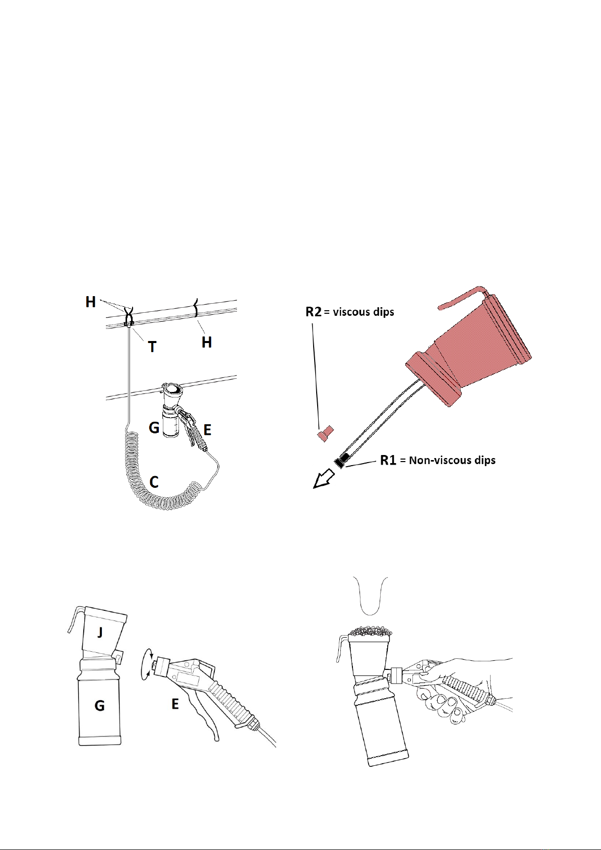
Routing the ring main tube (B) will depend on the parlour design and will be either at high level or low
level. If high level, it will ideally be positioned above the rump rail on each side with the coil (C)
connected via a 'T' fitting (T) fixed with cable ties (H). Alternatively it can be routed along the centre of
the parlour. Cable ties (H) will also be used to secure the ring main. (see Fig. 2 overleaf)
CAUTION: Do not over tighten cable ties as air flow may be restricted.
IT IS IMPORTANT that tubes are pushed fully into fittings to prevent leakage of air which may hamper
the operation of the system.
Foam (F) and Dip (D) Applicators should be positioned such that all milking points can be reached
comfortably without over-stretching the coils. In order to avoid the tubes becoming intertwined, install
the Red tubes so that the coiled section is closest to the spray gun and the Black tubes with the long
straight section adjacent to the spray gun. Extension kits are available to enable as many
Applicators as required to be installed.
If no suitable horizontal bar is available on which to hang the unit, the Plastic Hanging Hook supplied
may be either fitted to a suitable horizontal tube using 2 cable ties (crossed for stability), or can be
drilled with 2 holes and fitted (using 2 screws) to a flat surface.
OPERATION
Dipping Cups are provided with 2 restrictors (R1, R2);-
Black (R1) for non-viscous dip chemicals;
Red (R2) for viscous barrier/film-forming dips.
Unscrew bottle to fit appropriate restrictor (Fig. 3).
Switch on compressor. Remove enclosure lid of Regulator (A), open the tap and observe Pressure
Gauge. Gauge should read 3-4 psi (0.2 Bar). Turn tap to OFF and check that the air pressure remains
near constant. If air pressure falls rapidly, then check system for leaks and remedy.
Adjust the pressure by lifting the Regulator knob and turn clockwise to increase Pressure. Verify
pressure correct with a gun operational and, when correct, press down knob to lock.
Fill bottles (G) with suitable Foaming (or Dipping) teat product to the 250 ml mark –do not overfill.
Bottle can either be unscrewed from Applicator (J) with gun (E) attached, or after releasing from the
gun bayonet (Fig 4).