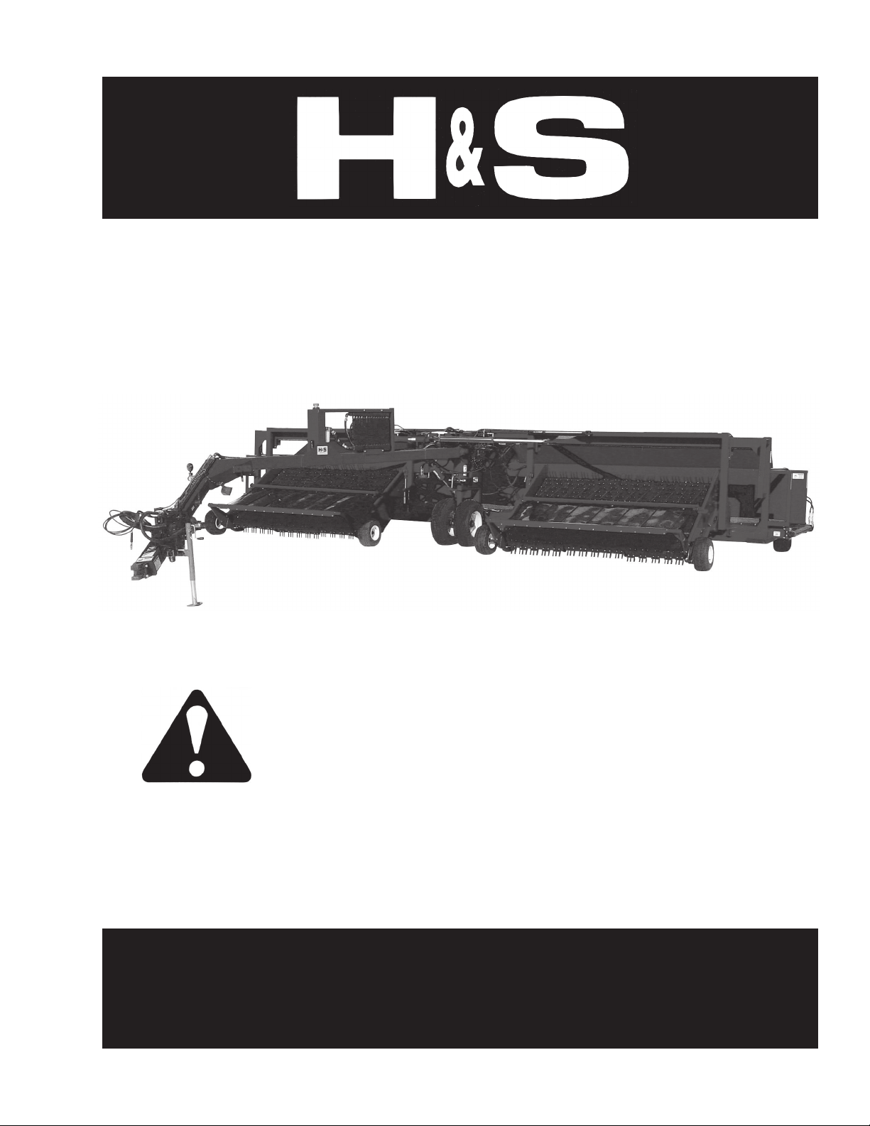
H&S TWIN MERGER Installation and maintenance instructions

Manufactured By
H&S MANUFACTURING CO.,INC.
P.O. BOX 768 (715) 387-3414 FAX (715) 384-5463
MARSHFIELD, WISCONSIN 54449
OPERATOR’S MANUAL
AND
PARTS LIST
WARNING READ AND UNDERSTAND THIS MANUAL
BEFORE OPERATING THIS EQUIPMENT
UNSAFE OPERATION OR MAINTENANCE OF THIS EQUIPMENT CAN RESULT IN
SERIOUS INJURY OR DEATH
HSMFG20208
TWIN MERGER

H & S
TWIN MERGER
PARTS AND OPERATOR’S MANUAL
CONTENTS
Warranty & Warranty Registration. . . . . . . . . . . . . . . . . . . . . . . . . . . . . . . . . . . . . . . . . . . . . . . . . . . . .1-2
Dealer Pre-Delivery & Delivery Checklist. . . . . . . . . . . . . . . . . . . . . . . . . . . . . . . . . . . . . . . . . . . . . . . .3
BeAlert Symbol. . . . . . . . . . . . . . . . . . . . . . . . . . . . . . . . . . . . . . . . . . . . . . . . . . . . . . . . . . . . . . . . . . . . . 5
Explanation of Safety Signs. . . . . . . . . . . . . . . . . . . . . . . . . . . . . . . . . . . . . . . . . . . . . . . . . . . . . . . . . . . 6
Danger - Warning Signs. . . . . . . . . . . . . . . . . . . . . . . . . . . . . . . . . . . . . . . . . . . . . . . . . . . . . . . . . . . . . .7
Warning - Owner Must Read and Understand. . . . . . . . . . . . . . . . . . . . . . . . . . . . . . . . . . . . . . . . . . . . 8
Bolt Torque Chart. . . . . . . . . . . . . . . . . . . . . . . . . . . . . . . . . . . . . . . . . . . . . . . . . . . . . . .. . . . . . . . . . . . .9
Tractor Set-up, Pre-Operation. . . . . . . . . . . . . . . . . . . . . . . . . . . . . . . . . . . . . . . . . . . . . . . . . . . . . 10-12
Hydraulic DriveAttachment. . . . . . . . . . . . . . . . . . . . . . . . . . . . . . . . . . . . . . . . . . . . . . . . . . . . . . . .12
Open/Closed Center Valve Conversion. . . . . . . . . . . . . . . . . . . . . . . . . . . . . . . . . . . . . . . . . . . . . . . . 13
Operation. . . . . . . . . . . . . . . . . . . . . . . . . . . . . . . . . . . . . . . . . . . . . . . . . . . . . . . . . . . . . . . . . . . . . . 13-14
Adjustments. . . . . . . . . . . . . . . . . . . . . . . . . . . . . . . . . . . . . . . . . . . . . . . . . . . . . . . . . . . . . . . . . . . . 14-16
Wiring Diagram - Joystick Plug. . . . . . . . . . . . . . . . . . . . . . . . . . . . . . . . . . . . . . . . . . . . . . . . . . . . . . .16
Optional Equipment. . . . . . . . . . . . . . . . . . . . . . . . . . . . . . . . . . . . . . . . . . . . . . . . . . . . . . . . . . . . . . . . .16
Lubrication. . . . . . . . . . . . . . . . . . . . . . . . . . . . . . . . . . . . . . . . . . . . . . . . . . . . . . . . . . . . . . . . . . . . . . . . 17
Decal Location & Identification. . . . . . . . . . . . . . . . . . . . . . . . . . . . . . . . . . . . . . . . . . . . . . . . . . . . 18-19
Trouble Shooting. . . . . . . . . . . . . . . . . . . . . . . . . . . . . . . . . . . . . . . . . . . . . . . . . . . . . . . . . . . . . . . . . . .20
Ordering Parts -About Improvements. . . . . . . . . . . . . . . . . . . . . . . . . . . . . . . . . . . . . . . . . . . . . . . . . 21
Figure 1 - 9’& 12’Twin Merger Main Frame. . . . . . . . . . . . . . . . . . . . . . . . . . . . . . . . . . . . . . . . . 22-23
Figure 2 - 9’& 12’Twin Merger Main Frame Continued. . . . . . . . . . . . . . . . . . . . . . . . . . . . . . . . 24-25
Figure 3 - 9’Twin Merger Left Pick-up Head. . . . . . . . . . . . . . . . . . . . . . . . . . . . . . . . . . . . . . . . . 26-27
Figure 4 - 9’Twin Merger Right Pick-up Head. . . . . . . . . . . . . . . . . . . . . . . . . . . . . . . . . . . . . . . .28-29
Figure 5 - 12’Twin Merger Left Pick-up Head. . . . . . . . . . . . . . . . . . . . . . . . . . . . . . . . . . . . . . . . 30-31
Figure 6 - 12’Twin Merger Right Pick-up Head. . . . . . . . . . . . . . . . . . . . . . . . . . . . . . . . . . . . . . .32-33
Figure 7 - 9’& 12’Twin Merger Pole Circuit Hydraulics. . . . . . . . . . . . . . . . . . . . . . . . . . . . . . . . 34-35
Figure 8 - 9’Twin Merger Electric Head Hydraulics. . . . . . . . . . . . . . . . . . . . . . . . . . . . . . . . . . . .36-37
Figure 9 - 12’Twin Merger Head Hydraulics. . . . . . . . . . . . . . . . . . . . . . . . . . . . . . . . . . . . . . . . . .38-39
Figure 10 - 9’& 12’Twin Merger Main Frame Hydraulics. . . . . . . . . . . . . . . . . . . . . . . . . . . . . . .40-41
Figure 11 - 9’& 12’Twin Merger Pick-up Lift Cylinder. . . . . . . . . . . . . . . . . . . . . . . . . . . . . . . . . . . . 42
Figure 12 - 9’& 12’Twin Merger Pole Swing Cylinder. . . . . . . . . . . . . . . . . . . . . . . . . . . . . . . . . . . . 43
Figure 13 - 9’Twin Merger Head Shuttle Cylinder. . . . . . . . . . . . . . . . . . . . . . . . . . . . . . . . . . . . . . . .44
Figure 14 - 9’& 12’Twin Merger Load Leveler Cylinder. . . . . . . . . . . . . . . . . . . . . . . . . . . . . . . . . . .45
Figure 15 - 9’Twin Merger Electric/Hydraulic Valve. . . . . . . . . . . . . . . . . . . . . . . . . . . . . . . . . . . .46-47
Figure 16 - 9’& 12’Twin Merger Electric Wiring Harness. . . . . . . . . . . . . . . . . . . . . . . . . . . . . . 48-49
Figure 17 - 9’& 12’Twin Merger PTOAssembly. . . . . . . . . . . . . . . . . . . . . . . . . . . . . . . . . . . . . . . . .50
Figure 18 - 9’& 12’Twin Merger HitchAssembly. . . . . . . . . . . . . . . . . . . . . . . . . . . . . . . . . . . . . . . . .51
Figure 19 - 9’& 12’Twin Merger Valve Mounting. . . . . . . . . . . . . . . . . . . . . . . . . . . . . . . . . . . . . . . . .52
Figure 20 - 9’& 12’Twin Merger Cross Conveyor Control Box. . . . . . . . . . . . . . . . . . . . . . . . . . . . . 53
Figure 21 - 9’& 12’Twin Merger OptionalAccelerator. . . . . . . . . . . . . . . . . . . . . . . . . . . . . . . . . 54-55
Figure 22 - 9’& 12’Twin Merger Crop Roller . . . . . . . . . . . . . . . . . . . . . . . . . . . . . . . . . . . . . . . . . 56
Service & Maintenance Records. . . . . . . . . . . . . . . . . . . . . . . . . . . . . . . . . . . . . . . . . . . . . . . .57
Specifications. . . . . . . . . . . . . . . . . . . . . . . . . . . . . . . . . . . . . . . . . . . . . . . . . . . . . . . .Inside Back Cover

WARRANTY
FILL OUT AND MAIL
IMMEDIATELY TO MAKE
WARRANTY EFFECTIVE
WARRANTY REGISTRATION
Date of Purchase
Purchaser Address
City State Zip
Product Model# Serial#
Dealer Address
City State Zip
Signature of Original Buyer
TM3/04
-1-
H&S MANUFACTURING CO., INC. WARRANTY
H&S Manufacturing Co., Inc. (“H&S”) warrants this product to be free from defect in material and workmanship. Except as
noted below, this warranty term is 120 days from the date of delivery of the product to the original purchaser by and authorized
H&S dealer. Under this warranty H&S will repair or replace, at it’s option, any covered part which is found to be defective in
material or workmanship during the applicable warranty term. In no case will the covered repair cost of a part or parts exceed
the replacement cost of that part. Warranty service must be performed by H&S or a dealer authorized by H&S to sell and/or
service the product involved, which will use only new or remanufactured parts or components furnished by H&S. This warranty
includes approved parts and labor to fix the product but does not include, and the purchaser is responsible for; any service call
and/or transportation of the product to and from the dealer’s place of business, for any premium charged for overtime labor
requested by the purchaser, and for any service work not directly related to any defect covered under this warranty. This
warranty includes only those components of the product manufactured by H&S. Warranty for any component not manufactured
by H&S including, but not limited to engines, batteries, tires, rims, hydraulic motors, pumps etc., are covered by the warranty if
any provided separately by their respective manufacturers.
This warranty in all its parts, is extended solely to the original purchaser of the product, is terminated upon any subsequent
transfer or sale from or by the original purchaser and extends no third party benefits or rights whatsoever.
This warranty does not include: (1) Any product that has been altered or modified in ways not approved by H&S; (2)
Depreciation or damage caused by normal wear, misuse, improper or insufficient maintenance, improper operation, accident or
failure to follow the product Operator Manual recommendations and product decal recommendations; (3) Normal maintenance
parts and service; (4) Repairs made with parts other than those available from H&S or performed by anyone other than H&S or
a dealer authorized by H&S to sell and/or service the product involved.
To secure warranty service the purchaser must report the product defect to a dealer authorized by H&S to sell and/or service
the product involved within the applicable warranty term together with evidence of the warranty start date and make the product
available to that dealer within a reasonable period of time.
THEREARE NO WARRANTIES WHICH EXTEND BEYOND THE DESCRIPTION ON THE FACE OF THIS WARRANTY. H&Sandthe
companies affiliated with it makes no warranties, representations, or promises, express or implied, as to the quality or
performance or freedom from defect of its products other than these set forth above and NO IMPLIED WARRANTY OF
MERCHANTABILITY, FITNESS OR FITNESS FORAPARTICULAR PURPOSE IS MADE. IN NO EVENT WILL THE DEALER, H&S
OR ANY COMPANY AFFILIATED WITH H&S BE LIABLE FOR INCIDENTAL OR CONSEQUENTIAL DAMAGES. The ONLY
REMEDY the purchaser has in connection with the breach of performance of any warranty on H&S products are those set
forth above.
The selling dealer has no authority to make any representations or promise on behalf of H&S, or to modify the terms or
limitations of this warranty in any way.
Mr. Owner: Before Operating-Read and Understand Operating and Safety Instructions.
H&S Manufacturing Co., Inc. truly believes you have made a wise choice and a sound and lasting
investment. Many years of development have made available these quality machines to assure you the
performance and reliability you need. We ask you to read the following agreement as this unit is
subject to this warranty and agreement and no other.

IMPORTANT!
Tear on dotted line, provide the information requested on
the card. The H&S Warranty is valid “only” after this card
is received and recorded at H&S Mfg. Co. Mail at
once. No postage is required in the U.S.A.
-2-

All shields and guards are in place and fastened
All grease fittings have been lubricated - (See lubrication guide in this manual).
All mechanisms are operating trouble free.
Belts and drive chains properly adjusted.
All bolts and fasteners are tight.
All decals are in place and legible.
All hydraulic hoses & fittings securely tightened.
AFTER COMPLETION, DEALER SHOULD REMOVE AND RETAIN FOR RECORDS
H&S
DEALER PRE-DELIVERY CHECK LIST
After the Windrow Merger has been completely set-up, check to be certain it is in correct operating order
before delivering to the customer. The following is a list of points to inspect. Check off each item as you have
made the proper adjustments and found the item operating satisfactorily.
Serial Number
(Dealer’s Name) Model Number
(Signature of Pre-Delivery Inspector) (Inspection Date)
DEALER DELIVERY CHECK LIST
This check list that follows is an important reminder of valuable information that should be passed on to the
customer at the time this Windrow Merger is delivered.
Check off each item as you explain it to the customer.
This delivery check list, when properly filled out and signed assures the customer that the Pre-delivery
service was satisfactorily performed.
Explain to the customer that the pre-delivery inspection was made.
Explain to the customer all the safety precautions they must excercise when operating this unit.
Explain to customer that regular lubrication is required for proper operation and long life of
machine. Show customer the lubrication section of Owner’s Manual.
Give the customer Owner’s Manual and make sure they read and understand all operating and
service instructions.
Record Serial Number on page 21 of this Manual.
Have customer sign a completed “Warranty Registration,” and mail it promptly.
‘
‘
‘
‘
‘
‘
‘
‘
‘
‘
‘
Date Delivered Dealer’s Name
By
Signature of Original Buyer
-3-
Note: Warranty is not valid until warranty card is completed and returned to H & S Mfg. Co., Inc.
‘
‘
(Remove Dealers File Copy At Perforation)

-4-

BE
ALERT! YOUR SAFETY
IS INVOLVED.
THIS SYMBOL IS USED THROUGHOUT THIS BOOK WHENEVER YOUR PERSONAL SAFETY IS
INVOLVED. TAKE TIME TO BE CAREFUL. REMEMBER: THE CAREFUL OPERATOR IS THE BEST
OPERATOR. MOST ACCIDENTS ARE CAUSED BY HUMAN ERROR. CERTAIN PRECAUTIONS
MUST BE OBSERVED TO PREVENT THE POSSIBILITY OF INJURY OR DAMAGE.
TRACTORS
This operator’s manual uses the term “Tractor” when identifying the power source.
-5-
H & S MANUFACTURING CO. INC.

RECOGNIZE SAFETY INFORMATION
This is the safety-alert symbol. When you see this symbol
on your machine or in this manual, be alert to the potential
for personal injury.
Follow recommended precautions and safe operating
practices.
UNDERSTAND SIGNAL WORDS
A signal word- DANGER, WARNING, or CAUTION - is
used with the safety-alert symbol. DANGER identifies the
most serious hazards.
Safety signs with signal word DANGER or WARNING are
typically near specific hazards.
General precautions are listed on CAUTION safety signs.
FOLLOW SAFETY INSTRUCTIONS
Carefully read all safety messages in this manual,
and all safety signs on your machine. Follow all
recommended precautions and safe operating
procedures.
Keep signs in good condition. Immediately replace
any missing or damaged signs.
-6-

-7-

TRACTORS
This operators manual uses the term “Tractor” when identifying the the power source.
WARNING
TO PREVENT SERIOUS INJURY OR DEATH
Study The Above Safety Rules
ATTENTION - BE ALERT - YOUR SAFETY IS INVOLVED
BEFORE YOU ATTEMPT TO OPERATE THIS EQUIPMENT, READ AND STUDY THE FOLLOWING
INFORMATION. IN ADDITION, MAKE SURE THAT EVERY INDIVIDUAL WHO OPERATES OR WORKS
WITH THIS EQUIPMENT, WHETHER FAMILY MEMBER OR EMPLOYEE, IS FAMILIAR WITH THESE
SAFTEY PRECAUTIONS.
H&S Mfg. Co. always takes the operator and their safety into consideration and guards exposed moving
parts for their protection. However, some areas cannot be guarded or shielded in order to assure proper
operation. In addition, the operators manual and decals on the machine itself warn you of further
danger and should be read and observed closely.
-8-
KNOW HOW TO STOPMACHINE BEFORE STARTING IT.
If the machine becomes clogged or requires servicing, disengage the tractor hydraulics. Stop
the tractor engine, remove ignition key and allow all mechanisms to stop before cleaning or
working on the machine.
DO NOT attempt to perform maintenance or repair with tractor running, or tractor or merger
hydraulics engaged.
DO NOT step up on machine at any time.
NEVER manually feed material into the pickup.
DO NOT allow minors to operate or be near the machine.
DO NOT ALLOW PERSONNEL OTHER THAN THE QUALIFIED OPERATOR NEAR THE
MACHINE.
STAY CLEAR of machine when raising or lowering pickups or positioning pole, also when
changing pickup widths with hydraulics.
Keep hands and feet, and clothing away from pickup and conveyor belts WHEN THEY ARE IN
MOTION.
Loose or floppy clothing should not be worn by the operator.
Be sure the machine is clear of people, tools, and other objects before engaging tractor
hydraulics or tractor PTO.
NEVER start Windrow Merger until all guards and safety shields are secured in place.
STAY CLEAR of hydraulic lines. They may be under extreme pressure or heat.

-9-

MAIN TRACTOR PLUG
1. Black (Ground)
2. Red (Work Lights)
3. Yellow (Left Turn)
4. Purple (+12V to C. Box)
5. Green (Right Turn)
6. Brown (Tail Lights)
7. Blue (+12V to Fan)
Tractor wiring may differ. Check your tractor
manufacturers’ electrical diagram to match to Twin
Merger Electronics.
-10-
TRACTOR SET UP
There are a few things that can be done with the tractor set up to ensure the smooth efficient operation of
the Twin merger. The drawbar should be set up at least 17 inches off the ground. This may require the
drawbar to be “flipped”. This gives more clearance between the pole and left head wind gurad for opening
and closing. Also the drawbar should be extended in the farthest position to allow for easier turning. The
three point arms should be taken off the tractor to keep them from hitting the hydraulic shut-off valve
located at the front of the pole. The tractor must be equipped with a 1000 RPM 1-3/8” 21 spline PTO
shaft. The tractor should have a seven pin electric plug.
PRE-OPERATION
While in the transport position, check entire unit carefully before first operation. Tighten bolts, set screws,
and chains that might have come loose in handling. Lubricate as explained in the lubrication guide.
Install drawbar extension on drawbar. Install hitch pin (B) and rotate pin lock (C) over hitch pin. Tighten
3/4” nuts to 150 ft. lbs. (204N-m). Nuts will secure pin lock and hold extension tight to the drawbar.
Dimension “A” should be the same on each side as shown.
Attach Merger to tractor using 1” hitch pin (D) provided and install safety-locking device.
1.
2.
3.
DC B

-11-
PRE-OPERATION (Continued)
Slide pump on receiver and secure with pin (E) provided and install safety-locking device.
Slide spring loaded locking collar (F) on PTO yoke rearward, and slide yoke onto the tractor PTO shaft.
Release spring loaded collar. Be sure the pins fall into the grove of the tractor PTO shaft and collar
snaps forward into position. CAUTION: Do not use steel hammer to aid in joining PTO parts.
Remove weight from lift jack and place in storage position (G).
Connect four hydraulic hoses to the tractor (9’ pickups). Two hoses open and close the machine and the
other two supply oil to the electric/hydraulic solenoid valve for pickup heads.
Connect six hydraulic hoses to the tractor (12’ pickups). Two hoses open and close the machine, two
hoses raise and lower the left hand head and two hoses raise and lower the right hand head.
4.
5.
6.
7.
8.
FE G

HYDRAULICS
The tractor hydraulic system should have a minimum flow of 5 GPM and a minimum pressure of 2000 PSI.
This system is used to operate the pole cylinders and the cylinders controlling pickup heads. The PTO
driven self-contained hydraulic system on the Merger provides oil to the hydraulic motors operating the
pickup belts and cross conveyor belts. The Merger pole is the hydraulic reservoir. In case of a blown
suction hose, shut off tractor PTO and turn off valve located at the front of the pole. The fans for the oil
cooler radiators are located on the merger pole must be turning properly to keep oil cool during merger
operation. The oil filter should be replaced once a year and the oil should be replaced every other year or
when the oil becomes discolored.
-12-
PRE-OPERATION (Continued)
Plug the joy stick control box cord into the main wiring harness on pole (9’ head). Attach control box to
a convenient place on the tractor. The tractor hydraulic circuit must now be locked in the open position
to provide oil flow to the electric valve on merger. Operation of joysticks will now control raising/lowering
and sliding of pickup heads. * Connect plug for cross conveyor reversing / shut-off valves.
Run pickup and conveyor for several minutes to ensure proper assembly and lubrication. Successful
operation will be achieved by periodic adjustments and experience of the operator. Make sure to read
and understand the adjustments.
Check tires and inflate to recommended pressure. The front two tires (H) should be inflated to 90 PSI,
the gauge wheel tires (I) should be inflated to 50 PSI. The rear tires (J) should be inflated to 36 PSI.
9.
10.
11.
IHI
J

-13-
OPEN/CLOSED CENTER SYSTEM
VALVE CONVERSION (9’ HEAD)
The valve is supplied in a closed center configuration
suitable for use in circuits utilizing pressure compensated
pumps. For use in gear pumps (open center) circuits, a
conversion is required. The valve outlet section has a “T”
port, as shown in Fig. 1 with the tank return line plumbed into
it. This internal plug must be removed for open center
operation. The tank return line may then be plumbed into the
port. Be sure to save the hex plug for possible future use.
OPERATION
LOAD LEVELER
After engaging the PTO, the Load Leveler (B)
automatically transfers a portion of the machine
weight to the rear carry wheels, and to the
tractor drawbar.
B
CROSS CONVEYOR
TheTwin Merger can be set up to merge hay to the
right, left, or right and left.This can be done by
moving the toggle switches on the control box.
These switches can not be moved from one direction
to the other in one continuous motion. They are
designed to stop in the center position. Momentarily
relieving pressure on the switch will allow it to then
be moved in the other direction. Bringing both
switches to the center position will stop both cross
conveyors. The pick up heads will still be operating.
When both cross conveyors are stopped, this allows
the operator to pick up small amounts of hay and store
it in the cross conveyor. The operator can then
go back to a windrow and select the direction of
travel and resume merging. The pickup head and
cross conveyor speed should be controlled by
adjusting the tractor throttle. By controling the speed
this way, the hydraulics will run at a cooler
temperature. Opening and closing should be done
on level ground and not while moving.
Fig. 1

ADJUSTMENTS
TAIL WHEEL
The tail wheels are located at the rear of the merger.
Located on each tail wheel pivot spindle is an
adjustable brake assembly. Adjust the brakes by
tightening bolt (A). The brakes should have enough
tension to prevent zig-zag motion, but still allow the
wheel to pivot when making corners. Improper
adjustment will cause severe tire wear and damage
to merger.
OPERATION (Continued)
-14-
TRANSPORT LOCKS
There are three transport locks on the merger. All locks should be used when transporting the unit, and
must be in the open or storage position when operating the merger. The transport locks (ball valves) (C)
for the heads are located at the cylinders that are used to raise and lower the heads. These cylinders are
located to the “inside” of the heads. The pole transport lock is located near the bend in the pole (D).
Transport speed should not exceed 20 M.P.H.
FRAME GAUGE WHEELS
There are two frame gauge wheels used on each
Twin Merger. Their sole purpose is to keep the
frame from contacting the ground in uneven
terrain. The picture to the right shows the frame
gauge wheels in the working position. The gauge
wheels must be raised to transport merger.
Failure to do so may cause damage to the frame
gauge wheel assembly. To raise gauge wheels
remove pin (E) raise wheel and insert pin back
into the same hole.
C D
E
A

-15-
PICKUP ADJUSTMENT
Pickup belts may be adjusted by tightening the take up bolt (B) located on both ends of the pickup. The
flange bearing bracket bolts (C) must be loosened before adjustment, and tightened after the desired belt
tension is attained. Proper belt tension will be achieved when 1-1/2” of slack can be pulled in the center of
the two outside belts with minimal resistance. DO NOT tighten pickup belts excessively. Over tightening
may cause damage to belts or rollers. Loose belts will cause unnecessary tooth wear and breakage.
Pickup height may be adjusted by adjusting the
gauge wheels located at both ends of the heads.
Pull pins (D) and rotate gauge wheels until proper
adjustment is achieved. Proper adjustment will allow
teeth to run 1/2” above the ground. Excessive tooth
wear and breakage will occur if teeth are touching
the ground. Adjust both sides equally.
WIND DEFLECTOR ADJUSTMENT
The wind deflector can be raised for heavy crop
conditions, or lowered for lighter crops. The
adjustment is made by repositioning the pins
located on each end, in the front of each pickup
head as shown (E). Overall transport width can be
made considerable narrower, by removing pins
(E) at each end of the pickup head.
The entire wind deflector can be pivoted
backward, toward the cross conveyor. To lock into
transport position, reinsert pin (E) into hole
(F) shown.
ADJUSTMENTS (Continued)
EF
BC
D

-16-
ADJUSTMENTS (Continued)
CONVEYOR ADJUSTMENTS
The cross conveyor belt tension can be adjusted
by tightening the take up bolts (G) located on the
two rollers located at the center of the machine.
Proper tension may be achieved by compressing
the springs to 3-1/4”.
OPTIONAL ACCELERATOR ADJUSTMENTS
Adjust cam (H) evenly on both sides of the
accelerator to tighten chain and square accelerator
to frame. Improper adjustment will cause excessive
chain wear.
WIRING DIAGRAM
Joystick Plug (9’ Head)
1. Red-Blk. (Right Head Up)
2. Orange (Left Head In)
3. Green (Right Head In)
4. Purple (+12V)
5. Red (Right Head Down)
6. Blue (Left Head Down)
7. Orange-Blk. (Left Head Out)
8. Green-Blk. (Right Head Out)
9. Blk.-White (Left Head Up)
OPTIONAL EQUIPMENT
The optional cross conveyor stop was designed
to allow the operator to stop both cross conveyors
and still have the pickup heads operate. This
allows the operator to pick up small amounts of
crop and store this crop on the cross conveyor to
later discharge onto a windrow.
The optional accelerator is a attachment that is
needed when merging windrow cuts larger than
16’. The accelerator gently moves the crop over
the additional distance needed for the larger
windrow cuts.
G
H

LUBRICATION
There are 42 grease fittings on your base merger. There are two zerks on the optional accelerator. If these
are lubricated properly and often enough, it will prolong the life of the merger. Grease daily during normal
use and before and after storage and after power washing. Use a good grade of high quality grease.
Make sure grease comes out around the shaft on the sleeve type bearings. On the sealed ball bearings,
grease should be added slowly until a slight bead forms at the seals indicating the correct amount of
lubricant. Wipe off excess grease to prevent accumulation of grit around the bearings. During normal use,
oil roller chains daily (Optional accelerator only).
(8) Cross Conveyors - one on each pillow block
bearing (2 each on ends, 4 in the center
(8) Pickup Heads - one on each end of each pickup
idler roller (bottom) and one on each end of pickup
drive roller (top).
(4) One on each Tailwheel
(8) Two on each side of each pickup head pivot.
(2) Center Axle Mount.
(3) Pole Pivot pin.
(4) One on each pickup gauge wheel pivot.
(3) One on each end of PTO shaft.
(2) One on each wind deflector (Right End).
A.
B.
C.
D.
E.
F.
G.
H.
I.
-17-
H
F E I B D
B G B C A B

DECAL LOCATION
Your H&S Twin Windrow Merger was manufactured with operator safety in mind. Located on the windrow
merger are various decals to aid in operation, and warn of danger or caution areas. Pay close attention to
all the decals on your windrow merger.
DO NOT REMOVE ANY OF THESE DECALS. IF DECALS ARE LOST, DAMAGED, OR IF
WINDROW MERGER IS REPAINTED, REPLACE DECALS. REMEMBER: DECALS ARE
FOR YOUR PROTECTION AND SAFETY.
Listed below are the decals on your Twin Merger. These decals may be ordered individually by part number
or by ordering a complete set.
ITEM PART NO. DESCRIPTION
A. 3398A (4) Danger - Stay Clear of Moving Parts
B. 31401 (3) Danger - Stay Clear of Merger
C. 1494K (4) Warning - Do Not Remove Shields
D. 72203A Warning - Help Avoid Injury
E. H&S Patent Numbers
F. 11599 (2) Warning - Do Not Go Near Leaks
G. 711888 Jack Storage Position
H. (4) 2” x 9” Red Reflector
I. (10) 2” x 9” Amber Reflector
J. B12 (2) H&S Decal
K. B22 (2) H&S Decal
L. B8 (2) H&S Decal
M. 5896B (2) Danger - Rotating Driveline
N. 82602 Warning - Crushing Hazard
O. 12803A Hitch Mounting Instructions
P. 12803B PTO & Hydraulic Pump Mounting Instructions
Q. Weasler Rotating Driveline (H&S Decal 1494L)
R. 2204 (4) Danger - Stay Clear of Moving Parts
S. 11591 Attention: Raise Gauge Wheels
12306TM Complete Set of Decals
Paint - H&S Red
ZX21 Gallon
ZX22 Quart
ZX23 Pint
ZX79 Spray Can
-18-
R C I K I
Table of contents
Other H&S Farm Equipment manuals