AMC 1022 D User manual

1022 D
Standard Monitor
INSTRUCTIONS
AMC-1022 D WITH STANDARD SENSOR
INSTALLATION AND OPERATING INSTRUCTIONS
FOR THE AMC-1022 D SENSOR UNIT
IMPORTANT:
Please read these installation and operating instructions completely
and carefully before starting.
filename: Manual_amc1022D.doc
Revised, 5/21/2002
Copyright ©, May 2001, AMC
The Armstrong Monitoring Corporation
215 Colonnade Road South, Nepean, Ontario, Canada K2E 7K3
Tel: (613) 225-9531 • Fax: (613) 225-6965 • U.S. & Can. Toll Free: (800) 465-5777
E-mail: gas@armstrongmonitoring.com • Internet: www.armstrongmonitoring.com/gas/


AMC-1022D Monitor
i
TABLE OF CONTENTS
Section Title Page
1WARRANTY...................................................................................................................... iii
1.1 LIABILITY .................................................................................................................... iii
1.2 MODIFICATIONS AND SUBSTITUTIONS................................................................... iii
1.3 PRODUCT RETURN ................................................................................................... iii
2PRODUCT INFORMATION ................................................................................................iv
3PRODUCT DESCRIPTION................................................................................................. 1
4INSTALLATION.................................................................................................................. 6
4.1 LOCATION AND MOUNTING...................................................................................... 6
4.2 WIRING OF THE MONITOR & SENSOR MODULE(S)................................................ 6
4.3 CABLE SELECTION.................................................................................................... 6
5OPERATION AND CALIBRATION....................................................................................10
5.1 OPERATION...............................................................................................................10
5.2 CALIBRATION............................................................................................................10
5.2.1 ADJUSTMENTS......................................................................................................10
6PREVENTIVE MAINTENANCE .........................................................................................12
6.1 GENERAL ..................................................................................................................12
6.2 VERIFICATION OF OPERATION ...............................................................................12

AMC-1022D Monitor
ii
NOTE
This page intentionally left blank.

AMC-1022D Monitor
iii
1 WARRANTY
The AMC-1022D monitor is warranted against defects in material and workmanship for a period
of two years from date of delivery. During the warranty period, we will repair or replace
components that prove to be defective in the opinion of The Armstrong Monitoring Corporation.
We are not liable for auxiliary interfaced equipment, nor consequential damage. This warranty
shall not apply to any product which has been modified in any way, which has been repaired by
any other party other than a qualified technician or authorized AMC representative, or when
such failure is due to misuse or conditions of use.
1.1 LIABILITY
All AMC products must be installed and maintained according to instructions. Only qualified
technicians should install and maintain the equipment.
AMC shall have no liability arising from auxiliary interfaced equipment, for consequential
damage, or the installation and operation of this equipment. AMC shall have no liability for
labour or freight costs, or any other costs or charges in excess of the amount of the invoice for
the products.
THIS WARRANTY IS IN LIEU OF ALL OTHER WARRANTIES, EXPRESSED OR IMPLIED,
AND SPECIFICALLY THE WARRANTIES OF MERCHANTABLITY AND FITNESS FOR A
PARTICULAR PURPOSE. THERE ARE NO WARRANTIES THAT EXTEND BEYOND THE
DESCRIPTION ON THE FACE THEREOF.
1.2 MODIFICATIONS AND SUBSTITUTIONS
Due to an ongoing development program, AMC reserves the right to substitute components and
change specifications at any time without incurring any obligations.
1.3 PRODUCT RETURN
All products returned for warranty service will be by prepaid freight and they will only be
accepted with an R.M.A. number issued by AMC. All products returned to the client will be
freight collect.
WARNING
USING ELECTRICALLY OPERATED EQUIPMENT NEAR GASOLINE OR COMBUSTIBLE
VAPOURS MAY RESULT IN FIRE OR EXPLOSION, CAUSING PERSONAL INJURY AND
PROPERTY DAMAGE. CHECK TO ASSURE THE WORKING AREA IS FREE FROM SUCH
HAZARDS DURING INSTALLATION OR WHEN PERFORMING MAINTENANCE, AND USE
PROPER PRECAUTIONS.

AMC-1022D Monitor
iv
2 PRODUCT INFORMATION
Monitor Serial Number ………………..…………………………
Power Supply Requirements ……………………………...…… 120 VAC, 60 Hz
Operating Temperature Range ………………………………… 0°C to 40°C
Relative Humidity ………………………………………...……… 0 to 99% (non-condensing)
I/O Cards………………………………………………..…………
SENSOR or TRANSMITTER
Part No. Serial No. Type of Gas Low Alarm
Trip Point
High Alarm
Trip Point
Note:
Refer to sensor module manual for additional specifications.
Note:
All Armstrong Monitoring systems must be installed and maintained according to
instructions, to ensure proper operation. Only qualified technicians should install and
maintain the equipment.

AMC-1022D Monitor
1
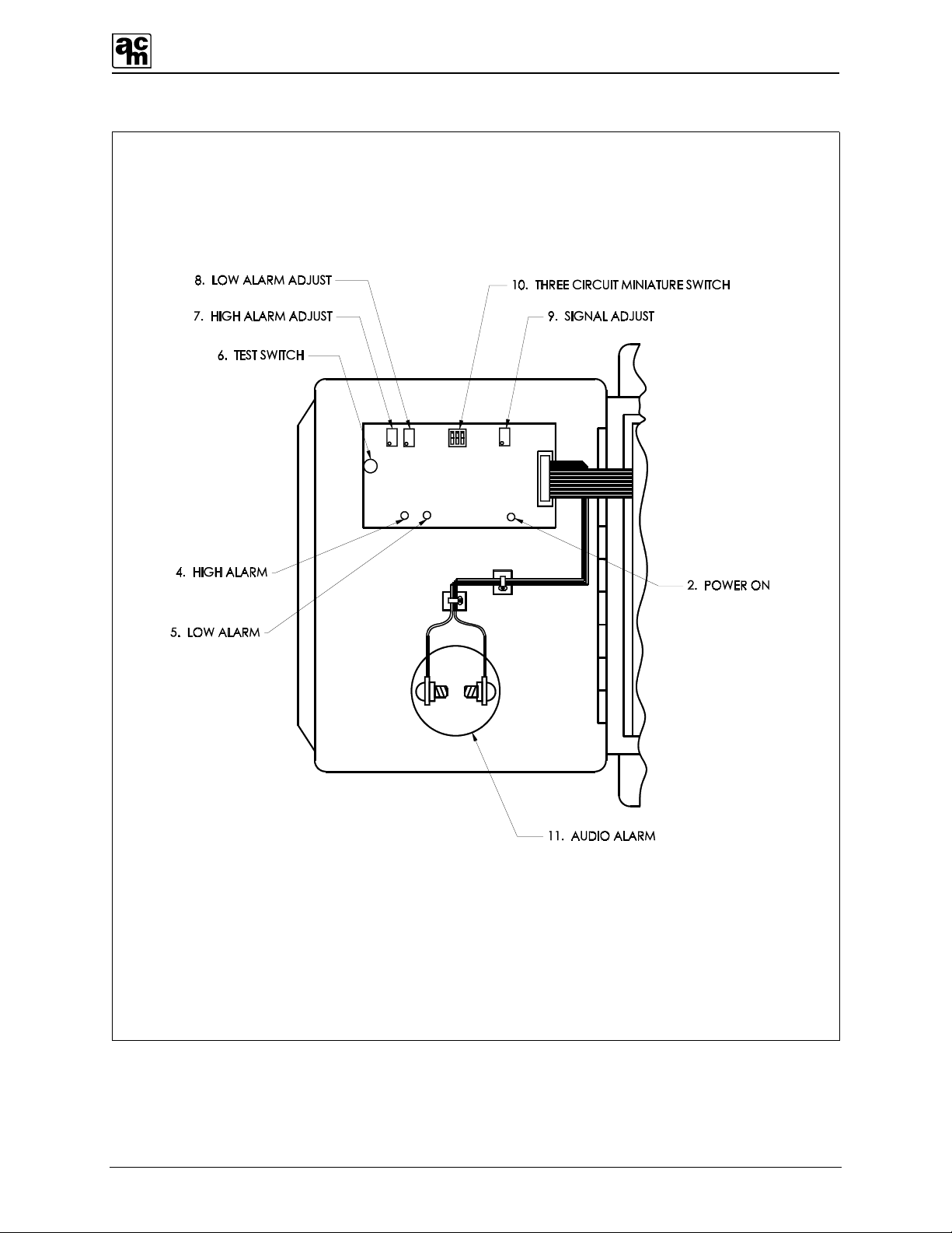
3 PRODUCT DESCRIPTION
The AMC-1022D is a multi-sensor gas monitoring system designed to continuously monitor for
traces of hazardous gases (listed in Product Information Section). It can be calibrated to detect
a wide variety of toxic gases. The monitor comes with the following features.
1. POWER SWITCH: Main AC power switch for all channels.
2. FUSE HOLDER: Front panel mounted for easy access to the fuse.
3. AUDIO ALARM INDICATOR: When operational, the buzzer will activate when a high
alarm condition occurs.
4. CLAMPS: To secure the front panel, restricting access to internal
controls.
5. POWER TERMINAL BLOCK: For line voltage connections (120 VAC, 60 Hz.)
6. POWER ON INDICATOR: Power is indicated by a green LED.
7. FAIL INDICATOR: Sensor module signal fail is indicated by an amber LED.
(only when this option is installed).
8. HIGH ALARM INDICATOR: High levels of gas are indicated by a red LED.
9. LOW ALARM INDICATOR: Low levels of gas are indicated by a yellow LED.
10. TEST SWITCH: The test switch is provided to electronically simulate alarms
in order to test the low and high alarm indicators, relays, and
the audio alarm indicator.
11. HIGH ALARM ADJUST: Sets the High alarm trip point.
12. LOW ALARM ADJUST: Sets the Low alarm trip point.
13. THREE CIRCUIT
MINIATURE SWITCH:
Each actuator on the miniature switch controls a different
circuit as shown in Figure 1. If the actuator is set in the UP
position, its corresponding circuit is ON. If the actuator is set
in the DOWN position, the circuit is OFF.
13.a) LEFT ACTUATOR: Provides a TEN minute time delay, when switch is ON, to
eliminate unnecessary alarms caused by momentary
exposure to high levels of gas.
13.b) MIDDLE ACTUATOR: Provides a FIVE minute time delay, when switch is ON, to
eliminate unnecessary alarms caused by momentary
exposure to low levels of gas.

AMC-1022D Monitor
2
13.c) RIGHT ACTUATOR: Controls the audio alarm indicator. When ON, the buzzer will
activate when a high alarm condition occurs.
14. RELAYS: There are two DPDT relays per channel which work with
high alarm and low alarm respectively.
15. TRANSFORMER:
Class II, step down transformers run the internal circuitry at
low voltages.
16. SENSOR TERMINAL
BLOCK:
For remote sensor module connections.
HI
LOW
THREE CIRCUIT
MINIATURE SWITCH
ON
Figure 1: Three circuit miniature switch.

AMC-1022D Monitor
3
P
O
W
E
R
A
I
L
F
L
O
W
H
I
G
H
ALARM
P
O
W
E
R
A
I
L
F
L
O
W
H
I
G
H
ALARM
AMC - 1022
GAS MONITOR
AMC - 1022
GAS MONITOR
11. AUDIO ALARM
INDICATOR
15. CLAMPS
4. HIGH ALARM
INDICATOR
5. LOW ALARM INDICATOR
3. FAIL INDICATOR
2. POWER ON INDICATOR
Figure 2: AMC-1022D monitor, front panel.

AMC-1022D Monitor
4
P. C. BOARD
INDICATOR
INDICATOR
INDICATOR
INDICATOR
+
-
Figure 3: AMC-1022D monitor, inside front panel.

AMC-1022D Monitor
5
Figure 4: AMC-1022D monitor, inside power / relay panel.

AMC-1022D Monitor
6
4 INSTALLATION
4.1 LOCATION AND MOUNTING
Care should be taken to securely fasten the AMC-1022D monitor unit (via four mounting holes
provided) to a solid, vertical, non-vibrating surface or structure at eye level. (See Figure 5 for
mounting dimensions.)
Note:
All cable entry MUST be through the BOTTOM of the monitor enclosure only. Other
entry locations will allow foreign materials to enter the enclosure, possibly causing
damage to internal components. Mounting hardware and conduit connections are NOT
supplied.
Mount the monitor in a NON-HAZARDOUS area (e.g. control room, manager’s office) where the
unit can be observed periodically.
Mount the sensor modules in areas where local concentrations of gases are unaffected by the
presence of ventilation systems.
4.2 WIRING OF THE MONITOR
POWER SUPPLY: The monitor operates on 120 VAC, 60 Hz. A class II step down
transformer runs the internal circuitry at low voltages. The power supply
connections are made at the power terminal block located inside the
monitor. (See Figure 6)
RELAYS: There are two DPDT relays which activate with high alarm and low alarm
respectively causing contact transfer. The contacts are available for
activating a remote alarm or an exhaust fan. Relays are rated 1/3 hp @
120 VAC/240 VAC, 10 Amps @ 28 VDC/120 VAC/240 VAC resistive. For
relay contact arrangement. (See Figure 7)
SENSOR: The remote sensor is wired to a sensor (–,sig,+) terminal block located on
the inner panel of the monitor (see Figure 6). All connections should be
made using shielded 3-conductor cable. Refer to Cable Selection
(Section 4.3) to select appropriate cable.
4.3 CABLE SELECTION AND WIRING
Connection should be made using 3-conductor shielded cable. For best signal transmission and
maximum noise rejection, run cable through steel conduit (cable shield must be grounded at the
monitor or power supply).

AMC-1022D Monitor
7
For proper selection of cable sizes and lengths for monitor-to-sensor and sensor-to-sensor
wiring, refer to the Cable Selection And Wiring section in the AMC-122X series module
manual(s).
4.0
DIMENSIONS
IN INCHES
6.7
4.0
1.35 0.37 8.75
9.5
Figure 5: Monitor mounting dimensions.

AMC-1022D Monitor
8
GND
NEUT
HOT
POWER
120 VAC
POSITIVE
SIGNAL
NEGATIVE
+
S
-
RED
YELLOW
BLACK
SIG.
REMOTE
AMC-122 X SERIES
SENSOR MODULE
SEE REMOTE
AMC-122 X SERIES
SENSOR MODULE
MANUAL(S) FOR
PROPER WIRING
Figure 6: Monitor power connections and remote sensor wiring.

AMC-1022D Monitor
9
RELAY
SOCKET
B-COM.
COIL
B-N.C.
B-N.O.
N.O.-A
N.C.-A
COIL
COM.-A
RELAY SOCKET
CONNECTIONS
RELAY DE-ENERGIZED
7 (13)
5 (9)
3 (5)
1 (1)
8 (14) COIL
6 (12) COM.
4 (8) N.O.
2 (4) N.C.
7 (13)
5 (9)
3 (5)
1 (1)
8 (14) COIL
6 (12) COM.
4 (8) N.O.
2 (4) N.C.
RELAY ENERGIZED
Figure 7: Relay contacts wiring diagram.

AMC-1022D Monitor
10
5 OPERATION AND CALIBRATION
5.1 OPERATION
Note:
BEFORE turning on the main power to the monitor, MAKE SURE all connections are
properly made.
When power is applied, the GREEN power LED will light. A one minute time delay eliminates
false alarms from occurring during the sensor’s warm up period. After this time delay, the unit
becomes fully operational. If time delays are required or the audio alarm indicator is not
needed, the three circuit miniature switch can be set accordingly. Refer to Section 3, Item 14
and Figure 1.
If any gas surrounding a sensor exceeds the low alarm trip point setting, the yellow LED and low
alarm relay will be activated. If any gas exceeds the high alarm trip point setting, the red LED,
high alarm relay and buzzer will be activated.
5.2 CALIBRATION
The monitor operates with remote sensor modules and on-site adjustments are made at the
sensor location. Refer to the AMC-122X series sensor module manual(s) for calibration
procedures.
5.2.1 ADJUSTMENTS
Adjustments are made using the two trimmers located along the top edge of each circuit board
as shown in Figure 8.

AMC-1022D Monitor
11
+
-
MULTIMETER
DIGITAL
CONNECT BLACK
( - ) LEAD TO GND.
PAD
P. C. BOARD
HI & LO
ADJUST
TRIMMERS
MEASURE
VOLTAGES
AT HI & LO
TEST POINTS
WITH RED
(+) LEAD
Figure 8: Trimmer adjustments and test point locations

AMC-1022D Monitor
12
6 PREVENTIVE MAINTENANCE
6.1 GENERAL
The monitor should be wiped clean with a damp cloth following a regular maintenance program.
Avoid spraying, submersion and other conditions that could cause a liquid to enter the monitor
and cause possible intrinsic damage to internal components.
6.2 VERIFICATION OF OPERATION
To verify the operation of the monitor and sensor module units, make sure that they are
responding to gas. This test should be performed regularly, every 3 months, but for more
demanding applications, verification should be performed on a weekly basis.

AMC-1022D Monitor
13
COM
COM
NCNO
NO NC
A
B
DEPTH
FRONT PANEL LAYOUT
AND FEATURES
TRANSFORMER
POWER AND
ALARM, LED
INDICATORS
POWER SWITCH
FUSEHOLDER
INDICATOR
AUDIO ALARM
P.C.BOARD FEATURES
RELAY CONNECTION DIAGRAM
POWER
120 VAC
(LOCATED INSIDE FRONT PANEL)
7.25
THREE CIRCUIT MINIATURE SWITCH
SIGNAL ADJUST
ALARM ADJUST
TEST SWITCH
INDICATOR INDICATOR
POWER ON
INDICATOR
HIGH ALARM
LOW ALARM
(HIGH,LOW)
TERMINALS
TRANSMITTER
17.5
16.8
0.37
1.0
10.0
1.0
0.37
OUTLINE OF P.C.BOARD
SYSTEM CONFIGURATION
ZONE
No.
QUANTITY
MODULES
PART No.
TYPE OF GAS
HOT
NEUT.
GND
DIMENSIONS, INTERNAL LAYOUT, & TRANSMITTERS
RELAY
SOCKETS
1
ZONE 1
MODULES
FOR YOUR SPECIFIC APPLICATION,
REFER TO THE CONFIGURATION CHART
AT THE UPPER RIGHT OF THIS DRAWING.
(HIGH & LOW DELAYS, AUDIO)
SHIELDED CABLE
3 WIRE
WIRE
GAUGE
CABLE LENGTH in FEET (metres)
18 AWG @ 150 ft MAX. BETWEEN UNITS
ACKNOWLEDGE
8.0
Figure 9: Typical Monitor Features, Dimensions and Wiring
Table of contents
Other AMC Accessories manuals