AMD Lasers PICASSO User manual

OPERATING INSTRUCTIONS MANUAL 7.1
PICASSO &PICASSO LITE
OIM 7.1 ENGLISH
Manufactured for
AMD LASERS, LLC
608 Rolling Hills Dr.
Johnson City, TN 37604 USA
T: +1 (866) 999-2635
F: +1 (678) 868-4108
www.amdlasers.com
©2009-2013 AMD LASERS, LLC. All rights reserved. AMDOIM7ENG0413

MT Promedt Consulting GmbH
Altenhofstr, 80
D-66386 St. Ingbert, Germany
Tel: +49 6894-58 10 20
Fax: +49 6894-58 10 21
www.mt-procons.com
PICASSO & PICASSO LITE
OPERATING INSTRUCTIONS MANUAL 7.1
SYMBOL DESCRIPTION
Do Not Throw Away
Consult with local laws with respect to medical
equipment disposal.
Laser Danger
Do Not Autoclave
Single Use Only
Consult Instruction For Use
Authorized Representative in the
European Community
Expiration Date
Manufactured for AMD LASERS, LLC
608 Rolling Hills Drive
Johnson City, TN 37604 USA
Fragile, handle with care
Only Applicable for USA
SYMBOL DESCRIPTION
Type B Applied Part
Warning Label
Class II Equipment
Must Read Manual Prior to Use
Battery Direction
Nonreturnable if Seal Is Broken
Optical Fiber
Manufactured Date
Standby/Ready Button
Protection Against Vertically Falling
Drops of Water (e.g. Condensation)
©2009-2013 AMD LASERS, LLC. All rights reserved.

Page 6 Page 7
TABLE OF CONTENTS
INTRODUCTION 7
SAFETY INFORMATION 7–9
CONTENTS OF PICASSO & PICASSO LITE 10–11
INDICATION FOR USE 12
SET-UP INFORMATION 12–16
WARNINGS 16–17
PRECAUTIONS 17
STEP-BY-STEP INSTRUCTIONS 17–23
PRODUCT SPECIFICATIONS 23–24
INSTRUCTIONS FOR ACCESSORIES 24–25
MAINTENANCE 26
CALIBRATION 26–27
INFORMATIONAL APPENDICES 28–35
LABELING & WARNING SIGNS 28–30
LIMITED WARRANTY | TERMS & CONDITIONS OF SALE 31–32
LIMITED LIABILITY 33
INTRODUCTION
The Picasso line of soft tissue dental lasers is designed for a wide variety of oral soft tissue and teeth whitening procedures. Picasso
& Picasso Lite lasers utilize solid state diodes as a laser energy source. The energy is delivered to the operating area by means of a
delivery system consisting of a flexible fiber connecting the laser source and the handpiece. The device is activated by means of a
footswitch which may be wired or wireless (See Page 15 & 16 for details).
Picasso & Picasso Lite lasers are intended for use by dentists, hygienists and/or authorized dental professionals on oral soft tissue as
defined by the Indication for Use (See Page 12). The Picasso Laser may also be used in teeth whitening procedures. The use of these
devices requires proper clinical and technical training. This manual provides instructions for professionals that have completed the
appropriate training.
When used and maintained properly, Picasso & Picasso Lite lasers will prove to be a valuable addition to your practice. Please
contact your authorized representative or AMD LASERS®if you have any questions or require assistance.
SAFETY INFORMATION
SAFETY PRECAUTIONS
DANGER: LASER RADIATION – AVOID EYE OR SKIN EXPOSURE TO DIRECT OR SCATTERED RADIATION!
WARNING: TO AVOID RISK OF ELECTRIC SHOCK, AC/DC ADAPTER MUST ONLY BE CONNECTED TO A SUPPLY MAINS WITH PROTECTIVE EARTH!
The user should read and be thoroughly familiar with this manual before operating this dental diode laser. The equipment should
be routinely inspected and maintained in accordance with the instructions given in the maintenance section of this manual. Use of
controls or adjustments or performance or procedures other than those specified herein may result in hazardous radiation exposure.
Unauthorized accessories not provided by the manufacturer may result in potential hazard.
All clinical procedures performed with Picasso & Picasso Lite must be subjected to the same clinical judgment and care as traditional
techniques. Patient risk must always be considered and fully understood before clinical treatment. The clinician must completely
understand the patient’s medical history prior to treatment. Exercise caution for general medical conditions that might contraindicate
a local procedure. Such conditions may include allergy to local or topical anesthetics, heart disease, lung disease, bleeding
disorders, sleep apnea, or an immune system deficiency. Medical clearance from a patient’s physician is advisable before treatment.
WARNING: Nominal Ocular Hazard Distance (NOHD) is 2 m from the distal end of the fiber.
Note: Laser equipment not in use should be protected against unauthorized use by removal of the key from the key switch.
Note: Opening this unit or adjusting components inside the unit will void the warranty since such actions may compromise the
performance of the laser system.
Failure to comply with the stated precautions and warnings may lead to exposure to electrical shock and/or exposure to radiation
sources. Please comply with all safety instructions and warnings.
Picasso and Picasso Lite have been tested and have been found to be compliant with the latest electrical safety standard (IEC60601-1
3rd Edition).
SAFETY INSTRUCTIONS
Follow these safety instructions before and during treatments:
• All operatory entrances must be marked with the appropriate danger warning sign.
• Do not operate the laser in the presence of explosive or flammable materials.
• Near infrared light (810 nm) from the laser can pass through the transparent components of the unprotected eye and is focused
on the retina at the back of the eye. This can cause permanent retinal burns and blindness. Patients and operating room personnel
should wear protective eyewear with an optical density (OD) of at least 5+ in the range of 800–820 nm during all procedures.
CAUTION: PERIODICALLY INSPECT EYEWEAR FOR PITTING AND CRACKING.
NOTE: For replacement, additional or prescription protective eyewear, please contact your authorized service representative or AMD
LASERS®.
• Do not look directly into the beam or at specular reflections.
• Never direct or point the beam toward the eyes.
• Remove or cover all highly reflective items in the treatment area.
• Press STANDBY on the control panel before turning the unit off.

Page 8 Page 9
• Always press STANDBY on the control panel before exchanging handpieces or removing the fiber optic connector from the unit.
• Move the circuit breaker (located on rear panel) to the OFF (0) position, remove the key, and place it in a secure location
before leaving the unit unattended.
• Remove all obstructions from the cooling vents on the device to ensure proper air flow and cooling of the device.
Safety Classification
The following safety classifications are applicable to the Picasso & Picasso Lite devices:
• Laser Radiation: Class 4 (US classification)
• Type of electrical shock protection: Class 1 (US classification)
• Degree of electrical shock protection: Type B Applied Part
• Laser not protected against water ingress: Ordinary Equipment
• Not suitable for use in the presence of flammable anesthetic mixtures
• Operation Mode: See Specifications
Safety Questions
Please direct safety questions to an authorized representative or directly to AMD LASERS.
SAFETY FEATURES
Circuit Breaker
Serves as a line switch to separate the unit from the main power supply: 0 = OFF, | = ON.
System Monitor
The system monitors emergency stop switch, remote key, footswitch attachment, fiber attachment, and output power. Any detected
error will stop the system.
Keyswitch
The unit can only be switched ON (key in horizontal position) with the proper key. Always turn the unit OFF (vertical position) and
remove the key when not in use.
STANDBY/READY Button
Once the circuit breaker and keyswitch are set to the ON position, the STANDBY/READY button on the keypad must be pressed to
enable the footswitch. One beep will sound to indicate that the system is ready for use. The STANDBY/READY button on the Picasso
will turn green. For the Picasso Lite, the LED light will begin to blink.
Footswitch
No laser energy will be emitted until the user presses down on the footswitch.
Emergency Stop
Press the red Emergency Stop button to instantly turn off the unit. The button will be in the out position. To reset the Emergency Stop
button, simply press again. The button will be in the pushed in position for normal operation. Only use the Emergency Stop for
emergencies.
Remote Interlock
The remote interlock feature allows the user to connect the laser to an operatory door trigger to disable the laser when the door
is opened. Please consult a qualified electrician to perform the proper wiring from the Remote Interlock Connector/Plug to the
operatory door.
The remote interlock plug must be inserted for normal operation. If the laser is not connected to a remote interlock, an auxiliary
connector, which bridges the connector contact pins, must be inserted into the Remote Interlock socket, located at the back of the unit.
The connector is attached by pushing it into place. Removal is accomplished by sliding the portion of the connector closest to the
laser housing away from the laser. The display will show the two dashes in the lowest position until the user has cleared the offending
interlock violation (insertion of the supplied remote interlock plug and/or closing the door).
Audible and Visual Display
The laser will give an audible beep and flash a light within the ready button while the laser is firing. The audible sound may be
adjusted or muted by the user. The visual display may not be turned off.
Functional Display
The Light Emitting Diode (LED) indicators on the front of the unit and control panel show the functional conditions of the system.
WIRELESS FOOT CONTROL COMPLIANCE
Mod.: PICASSO Frequency: 2.4G Hz
FCC ID: YXI-PFCA Voltage:1.5 Volts DC
IC: 9348A-PFCA 1.5V AA Alkaline Batteries Only
FCC:
15.19 (a) (3):
This device complies with Part 15 of the FCC Rules. Operation is subject to the following two conditions: (1) this device may not cause
harmful interference, and (2) this device must accept any interference received, including interference that may cause undesired
operation.
15.21:
The user’s manual or instruction manual for an intentional or unintentional radiator shall caution the user that changes or
modifications not expressly approved by the party responsible for compliance could void the user's authority to operate the
equipment.
15.105:
(b) For a Class B digital device or peripheral, the instructions furnished the user shall include the following or similar statement,
placed in a prominent location in the text of the manual.
NOTE:
This equipment has been tested and found to comply with the limits for a Class B digital device, pursuant to Part 15 of the FCC Rules.
These limits are designed to provide reasonable protection against harmful interference in a residential installation. This equipment
generates, uses and can radiate radio frequency energy and, if not installed and used in accordance with the instructions, may
cause harmful interference to radio communications. However, there is no guarantee that interference will not occur in a particular
installation. If this equipment does cause harmful interference to radio or television reception, which can be determined by turning the
equipment off and on, the user is encouraged to try to correct the interference by one or more of the following measures:
• Reorient or relocate the receiving antenna.
• Increase the separation between the equipment and receiver.
• Connect the equipment into an outlet on a circuit different from that to which the receiver is connected.
• Consult the dealer or an experienced radio/TV technician for help.
IC: RSS-GEN:
7.1.2 Transmitter Antenna
WARNING: Do not modify this equipment without written authorization of the manufacturer.
Canada Only: This device should be installed and operated in accordance with CAN/CSA-Z386-92: Laser Safety in Health Care
Facilities.
Information in this document is subject to change without notice. ©2013 AMD LASERS®. All rights reserved.
User manuals for transmitters shall display the following notice in a conspicuous location:
Under Industry Canada regulations, this radio transmitter may only operate using an antenna of a type and maximum (or lesser)
gain approval for the transmitter by Industry Canada. To reduce potential radio interference to other users, the antenna type and
its gain should be so chosen that the equivalent isotropically radiated power (e.i.r.p.) is not more than that necessary for successful
communication.
7.1.3 User Manual
User manuals for license-exempt radio apparatus shall contain the following or equivalent notice in a conspicuous location in the user
manual or alternatively on the device or both.
This device complies with Industry Canada license-exempt RSS standard(s). Operation is subject to the following two conditions:
(1) this device may not cause interference, and (2) this device must accept any interference, including interference that may cause
undesired operation of the device.
For Canadian Users only. A cable back up has been provided for the operation of the foot pedal as a wireless foot pedal is not
currently available for use in Canada. Please be sure to connect the cable between the foot pedal and the “FS” socket on the back of
the unit, verify that battery is removed, and then start your unit.

1
7
13
3
9
15
5
11
2
8
14
4
10
16
6
12
19 21
26
17B17A
23
20
25
22
27
18
24
Page 10 Page 11
# ITEM DESCRIPTION
1 Key Switch Turns Display of the Unit ON & OFF
2 Control Panel Displays & Controls the Parameters (e.g. Power Output, Presets, Aiming Beam
& Intensity, & Speaker Volume)
3 Emergency Stop Button Disables the Unit In the Event of an Emergency
4 Handle For Transporting the Unit
5 Handpiece & Holder, Disposable Tip Multi-Tip Handpiece/Fiber with Fiber Spool, Holder, & Disposable Tip
6 Fiber Spool Stores Fiber
7 Wired Foot Control Connector Port Connects Wired Foot Control to the Unit
8 Remote Interlock Connector Connects Interlock to the Unit
9 Cooling Vents Cooling Vents
10 Laser Standby/Ready Button Master ON/OFF Switch
11 AC Power Connector Connects Power Supply to the Unit
12 Fiber Connector Port Connects Fiber to the Unit
13 Quick Start Guide (QSG) Quick Start Guide (QSG)
14 Operating Instructions Manual Operating Instructions Manual
15 Transportation Box Transportation Box (Picasso Only)
16 Wireless Foot Control Cable (Optional) Optional Cable To Connect Wireless Foot Control Directly To the Device (Battery
Must Be Removed)
17A & 17B Laser Eyewear Protective Goggles (3) ANSI Z87, 800–820 nm, Optical Density (OD) 5+ Protective Eyewear Goggles
18 Laser Eyewear Protective Goggles Case Protective Case
19 Unit Keys Used to Turn Machine Off/On
20 Wireless Foot Control Wireless Foot Control Standard Picasso & Picasso Lite
21 AC Adapter
Connects the Unit & Net Power Supply
Input: 100–240 V 50/60 Hz, Output: 9 V–3A
AC/DC adapter is specified as a part of ME EQUIPMENT.
22 Power Cord Power Cord
23 Articulating Paper Sample of Paper to Be Used for Laser Tip Initiation
24 Remote Interlock Remote Interlock
25 Training Certification DVDs iCLE Training/Certification DVDs
26 Set-Up DVD Set-Up DVD
27 Laser Danger Sign Danger Sign for Operatory (Included at End of Manual)
CONTENTS OF PICASSO & PICASSO LITE

Page 12 Page 13
INDICATIONS FOR USE
Use of Picasso & Picasso Lite is generally indicated for incision, excision, vaporization, ablation and coagulation of oral soft tissues
including the following:
• Gingival troughing for crown impression
• Gingivectomy
• Gingivoplasty
• Gingival incision and excision
• Hemostasis and coagulation
• Excisional and incisional biopsies
• Exposure of unerupted teeth
• Fibroma removal
• Frenectomy and frenotomy
• Implant recovery
• Incision and drainage of abscess
• Leukoplakia
• Operculectomy
• Oral papillectomies
• Pulpotomy
• Pulpotomy as an adjunct to root canal therapy
• Reduction of gingival hypertrophy
• Soft tissue crown lengthening
• Treatment of canker sores, herpetic and aphthous ulcers of the oral mucosa
• Vestibuloplasty
LASER PERIODONTAL PROCEDURES
• Sulcular debridement (removal of diseased, infected, inflamed and necrosed soft tissue in the periodontal pocket to improve
clinical indices including: gingival index, gingival bleeding index, probe depth, attachment loss and tooth mobility)
• Laser removal of diseased, infected, inflamed and necrosed soft tissue within the periodontal pocket
• Removal of highly inflamed edematous tissue affected by bacteria penetration of the pocket lining and junctional epithelium
TEETH WHITENING INDICATIONS (PICASSO ONLY)
• Laser assisted whitening of teeth
• Light activation for whitening materials for teeth whitening
SET-UP INFORMATION
PICASSO & PICASSO LITE SET-UP
For details refer to Quick Start Guide. See Page 11 for identification of components.
1. Place unit in a clean, dry, and well-ventilated area.
2. Verify circuit breaker is in OFF position.
3. Insert key into key switch. Verify it is in the OFF position.
4. Verify Emergency Stop button is disengaged (UP position).
5. Connect footswitch.
6. Connect remote interlock.
7. Connect power cord to power connector on unit and plug into wall outlet.
8. Insert fiber into fiber connection port.
9. Set up Delivery System handpiece and fiber (See Page 19).
OPERATION INSTRUCTIONS
Turn ON Picasso & Picasso Lite
• Verify Red Emergency button (Page 11, Item #3) is pushed in.
• Turn circuit breaker to ON position (Page 11, Item #10).
• Rotate key clockwise to ON position.
• Select a PRESET or select a power level
• Press STANDBY/READY to place unit in READY Mode.
• Press foot control switch to fire laser and release to stop.
Turn OFF Picasso & Picasso Lite
• Press the STANDBY/READY button.
• Place handpiece back on handpiece holder.
• Switch circuit breaker to OFF position.
• Turn off and remove key from the unit, and place in a secure area.
CAUTION: VERIFY THAT THE FIBER OPTIC ASSEMBLY IS NOT TWISTED WHEN RETURNING THE HANDPIECE TO THE HOLDER. FIBER MAY BREAK IF
IT IS TWISTED OR CRIMPED.
DO NOT LEAVE THE SYSTEM IN AN UNCONTROLLED ENVIRONMENT WHERE THE TEMPERATURE COULD DROP BELOW 41°F (5°C) (E.G. THE
TRUNK OF A CAR). IF THIS OCCURS, ALLOW THE SYSTEM TO WARM UP TO ROOM TEMPERATURE FOR TEN TO FIFTEEN MINUTES BEFORE THE
UNIT IS ACTIVATED.
Warm-up Mode (Picasso Only)
If, during the self-diagnostic routine, the diode laser temperature is below 64°F (18°C), the system will go into warm-up mode. Follow
these instructions:
1. Press the STANDBY/READY button.
2. Press and hold the footswitch.
3. The STANDBY/READY light will flash and a beep will sound until the system is sufficiently warmed up. This may take up to two
minutes. The handpiece should be left in the holder with the fiber pointing down.
4. Hold the footswitch until the warm-up sequence stops.
Note: Always wear protective laser safety goggles during the warm-up, even while output power is negligible. The warm-up mode
will not function at temperatures below 41°F (5°C). If the temperature of the unit drops below 41°F (5°C), the system should be left to
warm up to room temperature for ten to fifteen minutes before the warm-up mode is activated.

4
1234
STAND
BY READY
# ITEM NAME ITEM DESCRIPTION
1 Cont/Rep Continuous or Repeating Modes
2 Presets
3 Power 0.5–7.0 W
4 Interval 20 ms–9.9 sec, increments of 10 ms
5 Duration 20 ms–9.9 sec, increments of 10 ms
6 Settings Language Selection, Aiming Beam, & Volume Settings
7 Standby/Ready Standby or Ready Button
8 Save Save Button
8
2
3
4
5
76
1
# ITEM NAME & DESCRIPTION
1 Diffusion: Aphthous Ulcers, Pulpotomies
2 Comfort Mode: Gingivectomies, Exposing Implants/Brackets/Teeth
3 Speed Mode: Surgery, Troughing, Frenectomies
4 Power Down
5 Power Display
6 Power Up
7 Aiming Beam Intensity: Off / Low / High
8 Volume Setting: Off / Low / High
9 Standby/Ready
1
9
2
8
5 64
37
Page 14 Page 15
PICASSO CONTROL PANEL
Control Panel UI
Programming Presets
STEP 1: Select desired type of laser operation mode: Continuous or Repeat.
Continuous Mode: In this mode, INTERVAL and DURATION are not available. POWER is able to be selected and saved as a preset.
Repeat Mode: In this mode, all the parameters (INTERVAL, DURATION, and POWER) can be adjusted and saved as a preset. Use the
arrow buttons to select desired interval and duration from 20 ms to 9.9 sec.
STEP 2: Select desired preset 1–4.
STEP 3: POWER. Select desired power settings 0.5–7 W using the arrow buttons.
STEP 4: INTERVAL / DURATION. Select desired interval and duration, available only on REP mode.
STEP 5: SAVE. Save desired settings by pushing the SAVE button for 2 seconds until the beep is heard.
STEP 6: READY. Push STANDBY button to put unit into READY mode.
Press the footswitch to fire the laser.
STEP 7: Repeat steps 1–6 to program additional presets.
Language Selection
English is the default language. Nine other languages are available: Italian / French / Spanish / Portuguese / Korean / Japanese /
Russian / Chinese / German
To select another language, press the SETTINGS button. The system will then enter into the language selection display. Press desired
language for two seconds, and the system will restart in the chosen language.
AIMING BEAM brightness settings
To select the brightness for aiming beam, first press the SETTINGS button. Then press the button to change the brightness
settings. There are five levels for Picasso: Off / Weakest / Weak / Strong / Strongest.
VOLUME settings
To select the volume, press the SETTINGS button. Then press the button to change the volume settings. There are five levels:
Mute / Quiet / Normal / Loud / Very Loud.
Custom Presets
The user is able to select POWER, INTERVAL, DURATION, CONT, or REP modes according to the operation. Pressing the SAVE button
stores the selected parameters to PRESETS 1–4. The data is saved when the confirmation beep sound is heard. User can select the
desired mode by selecting number 1–4.
PICASSO LITE CONTROL PANEL
Control Panel UI
Setting Picasso Lite
STEP 1: Insert tips on the handpiece
STEP 2: Select Mode: Speed / Comfort / Diffusion
STEP 3: Select STANDBY/READY button and step on the foot control to activate the laser.
Programming Presets
Picasso Lite features three fully customizable presets:
Speed Mode: 1.8 W Continuous Mode
Comfort Mode: 1.8 W Gated (Repeat) Mode; 30 ms on/off
Diffusion Mode: 0.5 W Continuous Mode
Saving Presets
Each of the three default presets can be customized for power level, aiming beam intensity, and speaker volume. To change a preset
from its default value, adjust power up or down to the desired level (0.5 W is the minimum setting). To adjust the brightness of the
aiming beam, press the button; there are three levels: Off/Low/High. To adjust the volume, press the button; there are three
levels: Off/Low/High. Next, press and hold the desired preset button for four seconds until the power display cycles off and on. The
new settings for the given preset have been saved.
Important: the unit only accepts one input at a time. It will perform based on the most recent input.
WIRELESS FOOT CONTROL
Instruction for Use
STEP 1: Place wireless foot control on the floor.
STEP 2: To open the cover, apply pressure to the right side of closed foot switch with your foot.
STEP 3: To operate the wireless foot control, apply pressure to enclosed foot switch with your foot. The green LED Indicator light glows
to indicate that the foot switch is operating when you step on the pedal to fire laser.

Insert foot control cable in
connection labeled F.C.
Corded Connection
FIGURE 11: FIBER SPOOL FIGURE 12: MULTI-TIP HANDPIECE & FIBER
Page 16 Page 17
STEP 4: To close the cover, push down sharply on arrow at front of cover with the ball of your foot.
Corded Connection Option for the FOOT CONTROL
Your wireless foot control has a corded connection option. This will allow you to use the foot control as a wired foot control if
preferred. To use the corded connection, connect the optional foot control cable to the F.C. Port on the back of the foot control and to
the back of your laser on the receptacle marked F.C. Remove the battery for wired operation.
CORDLESS FOOT CONTROL BATTERY REPLACEMENT
When the red indicator light is blinking on the cordless foot-control, the batteries are low and need to be replaced. Turn off unit, and
switch key to off position. Remove the battery cover and remove the batteries. Discard the batteries as required by applicable laws
and regulations. Replace with a new alkaline AA size battery as indicated in the battery compartment. Replace battery cover and
verify operation by depressing the foot-control button, returning the unit to standby, and viewing the green activity light.
WARNINGS
DANGER: DO NOT USE IN THE PRESENCE OF FLAMMABLE ANESTHETIC MIXTURE WITH AIR, OXYGEN, OR NITROUS OXIDE.
DO NOT RE-USE DISPOSABLE OR SINGLE-USE ITEMS. FAILURE TO COMPLY MAY RESULT IN REINFECTION OR CROSS-INFECTION AND IS A
HAZARD TO THE PATIENT.
DO NOT USE THIS UNIT IF YOU SUSPECT IT IS FUNCTIONING IMPROPERLY OR OTHER THAN DESCRIBED HEREIN.
Eyewear
Post appropriate warnings for laser in use in operatories where the laser is to be used so that appropriate eyewear can be donned
before the entry into the operatory. The doctor, patient, assistant, and any other persons in the operatory during laser procedures
must wear the appropriate laser eyewear protection for the diode laser wavelength of 810 ± 10 nm with an optical density (OD)
of at least +5. Class IV laser radiation is hazardous to the eye from the direct beam and diffuse reflections. It also represents a
significant skin and fire hazard. Safety eyewear not designed to this specification is not suitable for use with Picasso lasers. Laser
protective eyewear is available from your AMD LASERS representative.
Anesthesia
If anesthesia is required for treatment, closely monitor patients for signs of pain or discomfort. If such signs are present, adjust
settings, apply anesthesia, or cease treatment, if necessary.
Adjacent Structures
Picasso and Picasso Lite are designed to remove soft tissue. Therefore, always be aware of adjacent structures and substructures
during treatment and monitor them closely. Be extremely careful not to penetrate or ablate underlying or adjacent tissues. Do not
direct laser energy toward hard tissues, such as tooth or bone. Directing laser toward amalgam, gold, metallic surfaces or reflective
surfaces can result in laser beam reflection and/or scattered radiation.
Suction
Use high-speed suction as required to maintain a clear field of vision during treatment. Do not use Picasso and Picasso Lite if you
cannot clearly see the treatment site. It is recommended that a smoke evacuator or in-line filter be used to capture the plume during
the treatment of herpetic lesions, oral papillomas, and whenever possible. It is recommended that personnel wear a half face
respirator/clinical mask with proper HEPA™ filtration. The plume should be regarded as a source of active biological material as it
may contain viable tissue particulates.
Training
Only licensed professionals who are certified in Class 4 laser use and have read and understood this Operating Instructions Manual
shall use this device. AMD LASERS®assumes no responsibility for parameters, techniques, methods, treatments, or results. Clinicians
and/or operators must use their own clinical judgment and professionalism in determining all aspects of treatment, technique, proper
power settings, interval, duration, etc. A six hour laser certification course is available from AMD LASERS prior to use.
Heat Generation
The end of the fiber optic cable, disposable tips, and non-disposable tips, cannulas, and the handpieces may become hot during use.
Avoid unnecessary contact with tissue.
Disposable Tips
The disposable tips are designed and labeled for SINGLE USE only. These tips are not meant to be bent more than one time, and
bent no more than 90°. They are designed to be bent once to the preferred angle, used on a single patient, and then disposed of
properly. Bending the disposable tip more than once in an unintended manner is a risk to the fiber optic cable inside the cannula
leading to potentially lowered power output. When the handpiece is not in use, place protective cap over the tip to prevent dust or
contamination.
Additionally, bending the metal cannula in the Disposable Tip in an unintended manner can lead to a breakage resulting in a
potential sharp point which could puncture the skin of the patient or office personnel. Care should be taken to not bend the metal
cannula multiple times.
CAUTION: ALWAYS CHECK FOR PRESENCE OF THE AIMING BEAM BY SHINING THE TIP ONTO A NON-REFLECTIVE SURFACE BEFORE FIRING THE
LASER. IF THE AIMING BEAM SETTING ON THE DEVICE IS NOT “OFF” AND YOU DO NOT SEE THE AIMING BEAM, DO NOT USE THE TIP. IT MAY
BE BROKEN WHICH COULD RESULT IN HEATING OF THE METAL CANNULA POTENTIALLY CAUSING AN ACCIDENTAL BURN TO THE PATIENT.
PRECAUTIONS
AMD Picasso and Picasso Lite Diode Laser Systems are for Dental Use Only according to the Indications for Use in this OIM Version
7.1 of the manual. The laser is to be used under the supervision of a Dental professional.
Laser tips, once initiated, are extremely HOT. Touching flammable surfaces with an initiated tip is not recommended.
Periodic cleaning of the tip during procedures is required to keep the efficiency of the heat transfer. If removing coagulum, use
CaviCide™ or other equivalent solution following manufacturer’s instructions. If using any product containing alcohol, make sure to
allow tip to air dry fully prior to re-initiating the tip.
When placing the handpiece on the laser holder, make sure to have the tip pointing away from all plastic articles to avoid damage to
the plastic and/or the tip.
Units can only accept one input at a time. Laser settings will reflect the last input from the user.
CAUTION: DIODE LASERS ARE ATTRACTED TO MELANIN AND HEMOGLOBIN. POWER LEVELS ARE INVERSELY RELATED TO THE AMOUNT OF
PIGMENTATION AND VASCULARITY OF THE TARGETED TISSUE. AS PIGMENTATION VARIES FROM PATIENT TO PATIENT, START WITH THE LOWEST
POWER SETTING AND INCREASE AS NEEDED TO ACCOMPLISH THE PROCEDURE IN TISSUES WHICH HAVE LOWER MELANIN AND VASCULAR
CONTENT; USE ANESTHETIC AS NEEDED FOR PATIENT COMFORT.
STEP-BY-STEP INSTRUCTIONS
MULTI-TIP HANDPIECE WITH FIBER
The delivery system use in conjunction with removable and disposable tips consists of the Multi-Tip Handpiece/fiber assembly:
Multi-Tip Handpiece & Fiber
• Picasso (orange) / Picasso Lite (black)
• Length: 2 meters
• F.C. Connector and Handpiece
NOTE: Tips are not autoclavable.

FIGURE 13: DISPOSABLE TIP FIGURE 14: PROTECTIVE CAP
CLEAVER AUTOCLAVABLE HANDPIECE (REMOVABLE)
400 µm STRIPPER
STRIPPABLE FIBER:
400 µm
3 m in length
FC Connector
FIBER SPOOL
HANDPIECE TIP
CANNULA* ADAPTER
HANDPIECE HANDLE HANDPIECE BASE
1 2
QUAD TIP II
QUAD TIP I
to be discontinued in 2013
Page 18 Page 19
Disposable Tips & Protective Cap
The advantage of a disposable tip over the traditional strippable and cleavable fiber is reduced set-up time since no stripping or
cleaving of fiber is necessary. This accessory device is an “applied part” per IEC 60601-1.
CAUTION: THE DISPOSABLE TIPS, WHICH ARE THE APPLIED PARTS (FIGURE 13), ARE FOR SINGLE USE ONLY AND MUST BE CLEANED PRIOR TO USE.
CAUTION: USE A DISINFECTING WIPE, SUCH AS CAVIWIPES™ TO CLEAN THE DISPOSABLE TIP PRIOR TO USE.
To install a disposable tip, remove the blue protective cap (Figure 14) and slide the tip over the handpiece until the tip is fully seated.
You should hear and feel a slight ‘click’ when the tip snaps into place. To remove, pull gently on the tip and dispose of properly.
The tip initiation procedure is the same as in the case of traditional fiber (refer to the Quick Start Guide).
These tips have a bendable steel cannula allowing the user to customize the angle of each tip for a specific application. The tip can
be bent from 0° to a maximum of 90°. To bend the tip, pressure should be applied only in the middle of the metal cannula to form a
smooth curve. See the Quick Start Guide for additional information.
CAUTION: DO NOT BEND THE TIP MORE THAN 90 DEGREES. DO NOT BEND THE TIP AT THE BASE OF THE CANNULA.
Bending the disposable tip more than once in an unintended manner is a risk to the fiber optic cable inside the cannula leading to
potentially lowered power output.
After bending to the desired angle, the cannula should be visually inspected to ensure the tip is intact. Care should be taken to not
bend the metal cannula multiple times.
CAUTION: ALWAYS CHECK FOR PRESENCE OF THE AIMING BEAM BY SHINING THE TIP ONTO A NON-REFLECTIVE SURFACE BEFORE FIRING THE
LASER. IF THE AIMING BEAM SETTING ON THE DEVICE IS NOT “OFF” AND YOU DO NOT SEE THE AIMING BEAM, DO NOT USE THE TIP. IT MAY
BE BROKEN WHICH COULD RESULT IN HEATING OF THE METAL CANNULA POTENTIALLY CAUSING AN ACCIDENTAL BURN TO THE PATIENT.
THE QUADRA TIP I & II (PICASSO ONLY)
The Quadra Tip I & II above are used in conjunction with the Multi-Tip Handpiece for teeth whitening only. To use the Quadra Tips,
remove the protective cap from the end of the Quadra Tips and slide it onto the Multi-Tip Handpiece (MTHP) until you hear a click.
Slide the whitening adapter (1) onto the Quadra Tips (2) until it is fully seated.
Note: The AMD LASERS logo should face up on the adapter, and the notch on the adapter should align with the Quadra Tips peg.
The Quadra Tips are used 1–2 mm from the teeth once the bleach is placed on the teeth. Do not contact the patient with the Quadra
Tips. Follow the instructions provided with the Whitening Gel.
CAUTION: THE QUADRA TIPS ARE NOT AUTOCLAVABLE AND SHOULD BE COLD DISINFECTED ONLY. IT IS NOT A DISPOSABLE. SINGLE-USE ITEM.
CLEANING INSTRUCTIONS FOR THE MULTI-TIP HANDPIECE AND QUADRA TIPS
The use of CaviWipes™ Disinfectant and Cleaner is recommended for cleaning the Multi-tip Handpiece and Quadra Tips. Please
follow the recommended instructions provided by the manufacturer for use and disposal.
CAUTION: DO NOT USE ANY CLEANING AGENTS ON THE REFLECTIVE SURFACE OF THE WHITENING ADAPTER.
STRIPPABLE FIBER WITH STANDARD HANDPIECE
NOTE: The fiber optic cable, handpiece, and tips are shipped non-sterile.
The Delivery System consists of the following:
• Fiber Optic Assembly
• Handpiece
• Accessories: Adapter (to be used with disposable cannula)
• Picasso and Picasso Lite Handpiece Kit
NOTE: The standard fiber optic cable assembly is a 400 μm fiber.
NOTE: The fiber optic cable, handpiece, and tips are reusable accessories that require cleaning and sterilization before and
after each use. For instructions on cleaning and sterilization of the fiber optic cable, handpiece, and tips, refer to section
“MAINTENANCE”. Fiber optic cable is not autoclavable unless labeled as “autoclavable”.
*Customer supplied disposable tip (18 gauge or larger)
To connect handpiece to fiber optic assembly:
1. Loosen handpiece base (Figure 18)
2. Slide fiber through handpiece base, handle, and tip
3. Approximately 3–4 in (~7–10 cm) of fiber should protrude
4. Strip and cleave fiber (Figures 19 and 20)
5. Adjust to desired length
6. Gently tighten handpiece base to secure the fiber

FIGURE 18 FIGURE 19 FIGURE 20 FIGURE 21
Page 20 Page 21
DIRECTIONS FOR STRIPPING AND CLEAVING PICASSO & PICASSO LITE FIBER
Strippable fiber should be stripped/cleaved after each procedure.
1. Loosen the proximal end of the handpiece by unscrewing the handpiece base (Figure 18).
2. Push fiber optic cable into the base of the handpiece until fiber appears from the tip. Pull fiber approximately 3–4 inches
(~7–10 cm) out of the tip.
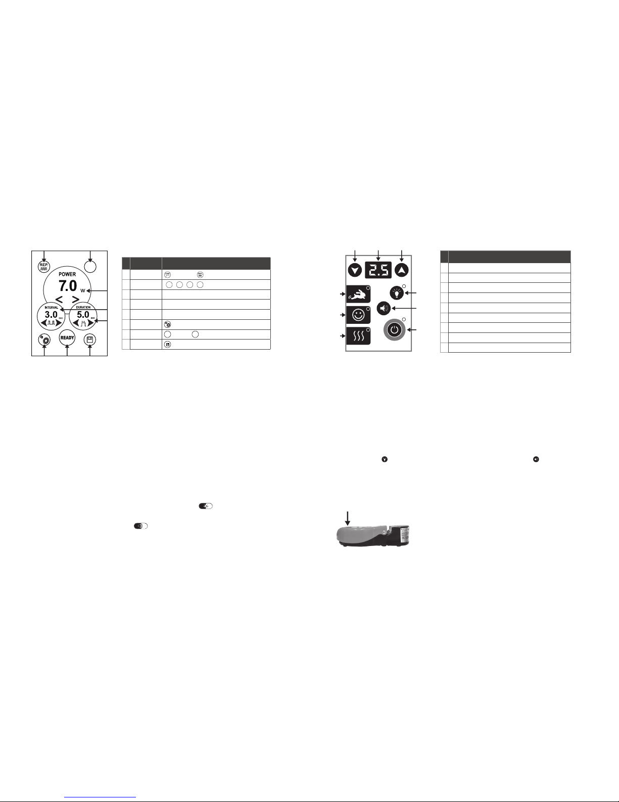
3. Slide the black stop marker on the stripper to approximately 1 inch (2.5 cm). Insert fiber into the stripper until the end of the
fiber touches the marker. Squeeze the red stripper handles pulling the stripper away from the handpiece in a smooth motion to
ensure that the fiber coating is cleanly removed. Grasp the fiber just above the handpiece with a firm grip (Figure 19).
4. Use the ceramic scribe to lightly scratch the end of the fiber. Place the fiber against a flat surface. Position the edge of the
scribe approximately ¼ inch (0.6 cm) from the end of the fiber, and make a gentle scratch perpendicularly across the fiber
(Figure 20), scribing (scratching) the surface at a 45° angle with the edge of the scribe. Make sure that the edge of the scribe
is always perpendicular to the fiber during cleave/scribing (Figure 21).
5. Hold the end of the fiber above the scribe between fingers and bend the end of the fiber until the end section breaks off. If the
fiber end is removed properly, the fiber should be flat.
6. Verify the scribe/cleave quality by aiming the fiber at a flat surface and observe the shape of the spot created by the visible
aiming beam. If the visible spot is a full circle, then the power output is optimal. If the circle is distorted, repeat only the cleave/
scribing procedure presented in steps 5 and 6 until you obtain a circular beam.
7. After the fiber is successfully cleaved, pull the fiber back through the handpiece, adjust the fiber end to desired length. Tighten
the handpiece base. Ensure that the fiber is secure by pulling lightly on the fiber optic cable at the proximal end.
8. Wipe the completed handpiece and fiber with a clean wipe similar to CaviWipe™.
CONTAMINATION CONTROL PROCEDURES FOR THE STRIPPABLE FIBER AND SURGICAL HANDPIECE
The contamination control suggested for fiber optic cable, handpiece, and interchangeable tips is the system sterilization method.
However, before sterilization, Picasso & Picasso Lite reusable accessories (handpiece, fiber optic cable, and interchangeable tips)
should be carefully cleaned per the following procedure.
NOTE: Fiber optic cable is not autoclavable.
CLEANING INSTRUCTIONS FOR PICASSO & PICASSO LITE SURGICAL HANDPIECE & THE STRIPPABLE FIBER OPTIC CABLE
The cleaning process is intended to remove blood, protein, and other potential contaminants from the surface and crevices of
reusable accessories. This process will also reduce the quantity of particles, microorganisms, and pyrogens present. Cleaning should
be performed prior to sterilization and must be conducted only by qualified office personnel trained to perform the procedure and
handle the Picasso and Picasso Lite Fiber Optic Delivery System.
Wear protective gloves when handling the contaminated delivery system. To disconnect the delivery system, follow the instructions for
delivery system assembly presented in the section “Delivery System”.
DISINFECTION INSTRUCTIONS FOR THE STRIPPABLE FIBER OPTIC CABLE
• Transport the delivery system to a decontamination/sterilization work area.
• Take the fiber and strip 1 inch (2.5 mm) off of the distal end of the fiber using the fiber cleaver. Make sure the part that has
debris is removed entirely. Dispose of the contaminated fiber tip accordingly.
• Prepare a sterilizing and disinfecting solution of a CaviCide™ equivalent and submerge approximately 12 inches (30 cm) of
the fiber’s distal end into the solution for 5 minutes. For high level of disinfecting, immerse the fiber end for 30 minutes at 68°F (20°C).
• After this process is completed, thoroughly rinse and dry the fiber.
• For disposal of CaviCide™ equivalent disinfecting solution, please follow the manufacturer’s instructions. CaviCide™ is not a
product or trademark of AMD LASERS, A DENTSPLY International Company
STEAM STERILIZATION FOR PICASSO AND PICASSO LITE SURGICAL HANDPIECE
Before sterilization, the handpiece must be cleaned and disassembled. For cleaning, follow the procedures previously described. To
disassemble the handpiece from the fiber optic cable, carefully loosen the handpiece base and slide handpiece off of the fiber optic cable.
The process of thermal sterilization with saturated steam under pressure is carried out in an autoclave. To perform this procedure,
follow these step-by-step instructions:
• Disassemble the handpiece, remove the rubber insert and store in a secure location for reassembly (do not autoclave the
rubber insert).
• Place the handpiece and interchangeable tips inside a single wrap self-seal autoclave pouch.
• Remove autoclave tray and place pouch(es) on the tray.
• Place tray inside the autoclave chamber and set controls to the following values: Temperature: 250°F (121°C), Pressure:15 PSI
(1 Bar), and Time Cycle: 20 minutes
• At the completion of the autoclave cycle, remove the tray and let the handpiece cool and dry.
• Attach the handpiece and the fiber optic cable to the unit for the next procedure.
CAUTION: DO NOT PLACE OR STACK OTHER DEVICES ON TOP OF THE FIBER OPTIC CABLE.
DISPOSAL OF USED FIBER TIPS, NON-WORKING FIBERS OR DISPOSABLE TIPS
Any portion of the fiber optic cable or disposable tip that comes in contact with a patient should be treated as a biohazard material
and properly disposed as governed by applicable laws and regulations.
Using Disposable Tips (Part No. DT3006005, DT3006010, DT4006005, DT4006010, DT2006020):
• Assorted bendable tips are available for use with both the Picasso and Picasso Lite Laser.
• Purple tips are 300 µm in size, available in 5 mm and 10 mm length.
• Orange tips are 400 µm in size, available in 5 mm and 10 mm length.
• Green tips are 200 µm in size, available in 20 mm length.
• For Picasso users only, if your laser has a Multi-tip Handpiece with an orange jacketed fiber and you want to use 200 µm and
300 µm tips, there will be a decreased power output at the end of the fiber relative to traditional 400 µm tips provided. To
establish equivalent power settings between the two tip sizes, increase the power 40%. If the Multi-Tip Handpiece is used with
a black jacketed fiber, it will perform the same with no adjustment in power required.
• 300 µm and 400 µm tips may be used according to the Picasso or Picasso Lite duty cycle up to 5 W. The 200 µm tips may not
be used above 3 W according to the established duty cycle. For any wattage, the surgical hand piece is also suitable. Only the
Quadra tip can be used at wattages above 5 W in the Picasso only for whitening purposes.
• Disposable tips are not sterile, and must be cleaned with a disinfectant wipe prior to use. If alcohol wipes are used, air dry
prior to installing the tip on the Multi-Tip Handpiece and initiating the tip for use.
CLINICAL APPLICATIONS
To efficiently remove tissue, it is imperative to understand the nature of the Picasso & Picasso Lite. Each laser operates unlike
traditional devices. The techniques mentioned below must be practiced and perfected to ensure efficient operation. Please study this
section carefully, practice on sample tissues, and attend a quality diode laser training seminar before using this device in a clinical
situation. The Picasso line of soft tissue lasers are designed for a number of surgical and non-surgical procedures. (See Indications for
Use, Page 12)
Only licensed professionals, who have successfully completed Picasso training and are certified in the use of Class IV lasers, have
read and understand this manual, and know how to correctly operate the system, should use this device.
The use of the Picasso line of lasers can be used in a contact and non-contact modes. Surgery requires the initiation of distal 2–3 mm
of fiber optic tip or fiber. Articulating paper is supplied with each laser for initiation. This initiation focuses laser energy to the tip.
Non-initiated tips are used in diffusion mode for the treatment of some ulcers and for other therapeutic reasons.
SOFT TISSUE SURGERY: CONTACT MODE
Cutting and coagulating soft tissue procedures can be utilized with either surgical handpiece or the multi-tip fiber handpiece and
a disposable tip. The fiber tip or disposable tip must be initiated for cutting to occur. Operator should start with the lowest energy
possible to achieve desired results. Disposable tips may not be used for procedures requiring more than 3.5 W.
Diode energy is highly absorbed by hemoglobin. The darker the pigment is the less energy is required to cut. Fibrous tissue requires
more energy to cut. Most surgeries can be performed in the Speed or Comfort modes and a range between 0.5–2.5 W with either
CONTINUOUS or PULSE MODES. Operator should try to use the least amount of power (WATTS) to achieve desired results.

SURGERY: CUT & COAG
INITIATED TIP
3.0 WATTS
WITH APPROPRIATE
ANESTHETIC
TROUGHING POSTERIOR
INITIATED TIP
2.2 WATTS
WITH APPROPRIATE
ANESTHETIC
TROUGHING ANTERIOR
INITIATED TIP
1.2 WATTS
DIFFUSION
NON-INITIATED TIP
0.5 WATTS
PERIO TREATMENT
NON-INITIATED TIP
1.4 WATTS
20 ms INTERVAL
20 ms DURATION
SURGERY: CUT & COAG
COMFORT SETTING
INITIATED TIP
2.0 WATTS
30 ms INTERVAL
30 ms DURATION
APHTHOUS ULCER &
HERPETIC LESION TREATMENT
NON-INITIATED TIP
0.8 WATTS
20 ms INTERVAL
20 ms DURATION
TEETH WHITENING
7.0 WATTS
1.5 sec INTERVAL
9.9 sec DURATION
2
1
3
4
2
1
3
4
Preset Continuous Mode (CONT) Repeat Mode (REP)
FIGURE 23
Page 22 Page 23
When tissue builds up during a cutting procedure, remove the tissue using a clean gauze pad. Do not use alcohol on an initiated tip.
Consult the accessories index for a complete listing of fibers and tips.
When procedure is complete, turn off the laser, appropriately dispose of the tip, clean handpiece with CaviCide™ or similar material,
cover with protective cover, and place the handpiece in the holder. Always clean and use a new tip prior to use.
DESCRIPTION OF LASER OPERATION MODES
Picasso and Picasso Lite have two modes of operation: CONTINUOUS and REPEAT (or PULSE) MODE. In CONTINUOUS mode, the
laser will deliver output radiation at the power level specified by the user for as long as the foot switch is held down. In REPEAT /
PULSE mode, the laser will deliver output radiation at the power level specified by the user and in a pulse format defined by the user
for Picasso or 30 ms for Picasso Lite. In pulse mode, the wattage is reduced meaning that a setting on 1.0 W in pulse mode may
produce only 0.5 W of energy at the tip. In this section, the operation of the laser is described.
PICASSO
The following figure (Figure 23) identifies the various Modes of Operation for the Picasso device:
PICASSO LITE
SPEED MODE
To select the SPEED MODE of operation, press the key marked with the rabbit symbol. In this mode, the preset from the factory is 1.8 W,
continuous operation while the foot control is depressed. This is a continuous mode of operation. The only variable parameter is the
output power. The user can increase and decrease power shown in watts by pressing the corresponding up/down arrow buttons.
To operate the laser in SPEED MODE, press the STANDBY/READY button. The laser will now deliver output radiation as long as the
user holds the foot switch down. An audible signal will be sounded while the laser is active and the ready button will flash.
SPEED MODE output power can be changed at any time using the up/down arrow buttons. The user may lock this new parameter
into the SPEED MODE setting by first selecting desired parameter for power and then by pushing and holding down the Speed button
for approximately 5 seconds. The system will momentarily blink off and then on again symbolizing the new parameter has been set.
COMFORT MODE
To select the COMFORT MODE of operation, press the key marked with the HAPPY FACE symbol. In this mode, the preset from the
factory is 1.8 W and 30 ms on time and 30 ms off time. This is a PULSED MODE of operation. The user can increase and decrease
power shown in watts by pressing the corresponding up/down arrow buttons.
Once the user has selected the desired wattage, the unit may be enabled by pressing the STANDBY/READY button. After the
STANDBY/READY button has been pressed, the user may operate the laser at this point by depressing the foot switch. The laser will
respond by outputting radiation at the desired power level for a period of 30 ms. An audible signal will be sounded while the laser
is active and the ready light will be flashing. At the end of the ON PULSE, the laser will pause for a period of 30 ms. After the OFF
TIME has passed, the laser will repeat this pattern for as long as the foot switch is depressed. Laser treatment may be interrupted at
any time by releasing the foot switch. To resume treatment, simply depress the foot switch.
The system will momentarily blink off and then on again symbolizing the new parameter has been set.
DIFFUSION MODE
To select the DIFFUSION MODE of operation, press the key with the three wavy lines. This is a continuous mode of operation. In this
mode, the laser is preset from the factory at 0.5 W. The only variable parameter is the output power. The user can increase power
shown in watts by pressing the corresponding arrow buttons.
To operate the laser in DIFFUSION MODE, press the STANDBY/READY button. The laser will deliver output radiation as long as the
user holds the foot switch down. An audible signal will be sounded while the laser is active and the ready button will flash.
DIFFUSION MODE output power can be changed at any time using the up/down arrow buttons. The user may lock this new
parameter into the DIFFUSION MODE setting by first selecting desired parameter for power and then by pushing and holding down
the DIFFUSION button for approximately five seconds. The system will momentarily blink off and then on again symbolizing the new
parameter has been set. The DIFFUSION MODE can be used with a non-initiated tip for the treatment of ulcers.
PRODUCT SPECIFICATION
GENERAL
• Dimensions L x W x H 9.5'' x 6'' x 6.2'' (240 mm x 150 mm x 160 mm)
• Weight: 2.0 lbs (1 kg) ± 20%
• Working Environment: Temperature 60°F/15°C–90°F/32°C, Humidity 25%–85% , Pressure 700 hpa–1060 hpa
• Storage: Temperature 50°F/10°C–122°F/50°C, Humidity 25%–85% , Pressure 700 hpa–1060 hpa
ELECTRICAL
• Output Voltage: +9.0 V DC
• Output Current: 5.0 AMPS
• Output Power Range: 45 Watts MAX
• External Fuses: None
• Main Control: Circuit Breaker
• On/Off Controls: Keyswitch, Circuit Breaker, Emergency Stop
• Remote Interruption: Remote Interlock Connector

FIBER 3–4 mm
CARBONIZATION
FIGURE 22
1 2
QUAD TIP II
QUAD TIP I
to be discontinued in 2013
Page 24 Page 25
LASER – PICASSO
• Laser Classification IV (4)
• Medium GaAlAs
• Wavelength 810 ± 10 nm
• Power Accuracy ± 20%
• Power Modes Continuous, Repeat Pulse
• Adjustable Pulse Duration 20 ms – 9.9 sec
• Pulse Interval 20 ms – 90 ms
• Delivery Fiber Diameter 400 µm
• Mode Whitening
• Continuous Mode Preset to 1.8 W continuous, adjustable from 0.5–7.0 W
• Repeat Mode Preset to 1.8 W pulsed, 30 ms on time (duration), 30 ms off time (interval).
Adjustable 0.5–7.0 W, 10 ms – 9.9 sec duration, 10–90 ms interval
• Whitening Mode Preset to 7.0 W, Repeating 9.9 sec duration, 1.5 sec interval
• Output Range 0.5–7.0 W ± 20%
• Laser Operation Note: 0.5–4.9 W Continuous Operations
5.0–7.0 W Intermittent Operation 5 min on, 4 min off or in standby mode.
OTHER LIGHT SOURCES
• Aiming Beam 632 nm ± 20%, max 5 mW, Class 1 laser
• Medium Laser Diode
LASER – PICASSO LITE
• Laser Classification IV (4)
• Medium GaAlAs
• Wavelength 810 ± 10 nm
• Power Accuracy ± 20%
• Power Modes Continuous, Repeat Pulse
• Pulse Duration 30 ms
• Pulse Interval 30 ms
• Delivery Fiber Diameter 200 µm
• Mode Speed, Comfort, Diffusion
• Speed Mode Preset to 1.8 W continuous
• Comfort Mode Preset to 1.8 W pulsed, 30 ms on time (duration), 30 ms off time (interval)
• Diffusion Mode 0.5 Watts, continuous
• Output Range 0.5–2.5 W ± 20% output
• Laser Operation Note: Intermittent operation 3 min on, 15 sec off or in standby mode.
INSTRUCTION FOR ACCESSORIES
INITIATING TIP
Focusing laser energy to the end of the fiber or tip is necessary for cutting and coagulation to occur. The better the initiation the more
focused and concentrated laser energy becomes. A sample of articulating paper is included with each Picasso laser. Select the SPEED
or DIFFUSION MODE preset and drag the tip onto the articulating paper while firing the laser.
A good ignition will cover 3–4 mm of the tip with a dark carbonization (Figure 22). Articulation paper is flammable and precautions
should be followed to prevent unintended combustion. Once initiated, do not touch the tip anywhere other than where cutting tissue is
a desired treatment. For more information on initiation please consult the training DVDs included with your laser.
Initiating the tip of the Diode Laser is necessary for all procedures which require cutting or tissue removal.
Using provided or replacement articulating paper, rub the paper while firing the laser to cover 3–4 mm of the tip with carbonization.
Articulating paper is flammable. Please use and dispose of the articulating paper using fire proof collection bins in order to prevent
accidental ignition of flammable materials. See Instructional video.
TEETH WHITENING (PICASSO ONLY)
Picasso teeth whitening should be performed only by trained personnel and as allowed by local, state and federal authorities.
Picasso is designed for fast, efficient laser whitening with a unique laser adapter, the Quadra Tip I & II and Whitening Adapter. Most
whitening is performed by first cleaning, pumicing the teeth, isolating the gingival and soft tissue mucosa with a liquid rubber dam,
and applying the whitening manufacturer’s bleach 2–3 mm thick on the teeth . Picasso has a built in whitening mode (Preset #4 on
the Picasso).
Prior to use, the operator must use the multi-tip handpiece and Quadra Tips as seen below. The Whitening Adapter must be attached
to the end of the Quadra Tips with care taken to ensure the AMD LASERS logo is facing up. The Quadra Tips do not make contact
with the patient during the whitening procedure. The Whitening Adapter is a disposable item included with your whitening kit. Refer
to the specific instructions supplied with your whitening kit.
To select the WHITENING operation, the user simply selects preset #4. This is a pulse mode of operation. In this mode, the mode is
preset from the factory at 7.0 W continuously for 9.9 sec with a 1.5 sec off time. Releasing the foot control will interrupt the 9.9 sec
cycle. The only variable parameter is the output power. To operate the laser in the WHITENING MODE press the STANDBY/READY
button. The laser will now deliver output radiation as long as the user holds the foot switch down. An audible signal will be sounded
while the laser is active and the ready button will flash.
The WHITENING MODE output power can be changed to a lower setting at any time using the up/down arrow buttons. The user
may lock this new parameter into the WHITENING MODE setting by first selecting desired parameter for power and then by pushing
and holding down the button for approximately 5 sec. The system will momentarily blink off and then on again symbolizing the new
parameter has been set. The Whitening procedure requires at least 5 W of power. Do not touch mucosa with the Quadra Tips during
the whitening procedure.
The whitening adapter (1) is disposable and the Quadra Tips (2) are nondisposable.

Page 26 Page 27
MAINTENANCE
DENTAL LASER UNIT AND PLASTIC BARRIERS MAINTENANCE
This unit requires little operator maintenance. Wipe down the system with a cloth dampened with a mild antiseptic or cleaning
solution–we recommend the use of CaviWipes™. Never use solvents or abrasive cleaners, which can damage the finish. Never pour
or spray any liquid on or directly over the control console.
Protective plastic barriers can be used to protect the carrying handle, touch pad, handpieces, and goggles and are customer supplied.
ANNUAL MAINTENANCE
Picasso & Picasso Lite should be serviced annually by a qualified, trained, and certified technician. Please contact your authorized
representative or AMD LASERS®to discuss extended service contracts and annual maintenance options.
To maintain compliance with the applicable IEC and CDRH regulations, all systems must be checked and verified that they are
functioning properly in the event the unit has been subjected to adverse environmental conditions such as fire, flood, mechanical
abrasion, solvent spillage, etc.
The following safety checks shall be carried out:
• Verify all labels are firmly in place.
• Verify disconnection of the remote interlock causes the laser to return to and remain in STANDBY.
• Verify the display indicates LASER FIRING when the foot switch is depressed.
• Verify the audible signal is active when the foot switch is depressed and laser emission is present.
• Verify the laser goes into and remains in STANDBY when the fiber is removed from the laser aperture.
TRANSPORTATION
Picasso & Picasso Lite lasers are susceptible to misalignment if not handled properly. The unit should ALWAYS be handled
carefully and never banged, jarred, jolted, dropped, or hit. Do not transport the unit unless it is completely packaged inside of its
transportation box. If you have any questions regarding transportation, please call your authorized representative or AMD LASERS®.
Calibration is required to maintain your laser in good operating condition. By regulation, power is allowed to vary a total of +/- 20%
from the established rated power. (21 CFR 1040.10).
If calibration shows a variation of more than +/- 20%, the laser needs to be returned to the AMD Laser Repair Center for repair.
CALIBRATION PROCEDURE
Picasso & Picasso Lite comes factory calibrated and certified for use. For accurate treatment results, the unit(s) should be calibrated
every 12 months following the date of manufacture. Due to the potential for electrical shock, personal injury, or death; calibration
should only be performed by authorized personnel. Improper calibration could lead to damage and failure to calibrate the laser.
CALIBRATION BY ANYONE OTHER THAN A CERTIFIED AMD LASERS TECHNICIAN WILL VOID THE WARRANTY.
To schedule calibration of your unit, contact your authorized representative or AMD LASERS®at (866) 999-2635 to obtain an RMA.
Calibration generally takes 5 business days (excluding holidays). Calibration of AMD LASERS units is performed with an output watt
meter and AMD LASERS calibration software.
It is highly recommended that the customer contact AMD LASERS, rather than performing the procedure itself. Utilizing these
procedures requires certain technical expertise and improper calibration could lead to damage and failure to calibrate the laser.
EQUIPMENT NEEDED: PC with Windows XP or better and a serial (RS-232) port. Laser power/energy display such as Ophir Model
II P/N 7Z01550 or equivalent. Power/energy meter for low power lasers with 810 nm wavelength capability and accuracy better
than +/- 3%, for example, Ophir power meter P/N 7z02637 or equivalent. AMD LASERS Calibration Software. AMD LASERS
Calibration Data Cable. #1 Phillips Head Screwdriver.
PICASSO
TURN LASER OFF AND UNPLUG PRIOR TO CALIBRATION PROCEDURE
Remove front and side panel
1. Set up software, and connect laser to computer. Reconnect front and side panel.
2. Turn laser “on” and fire the laser with the fiber tip approximately 1–2 mm from the power meter laser head.
3. Adjust the values in the appropriate fields to increase or decrease the output wattage to within +/- 20% of the desired setting.
4. When appropriate output power is reached, select “save” and proceed to the next setting.
5. Repeat this process until all fields have been properly adjusted.
PICASSO LITE
TURN LASER OFF AND UNPLUG PRIOR TO TESTING
Remove front panel
1. Move and place the jumper onto the test pin to enter calibration mode. Reconnect the front panel.
2. Turn laser “on” and fire the laser with the tip approx 1–2 mm from the surface of the power meter laser head.
3. Adjust the output values to within +/- 20% of the desired setting by using the “light” button to increase and the “sound” button
to decrease.
4. Data is saved automatically after adjustment.
5. Remove the short circuit test ring from the test pin when calibration is complete.
CALIBRATION SCHEDULE
Authorized by:
Purchase Date _____//______//___________ __________________________________
Calibration 1 _____//______//___________ __________________________________
(12 months after purchase date)
Calibration 2 _____//______//___________ __________________________________
(24 months after purchase date)
Calibration 3 _____//______//___________ __________________________________
(36 months after purchase date)
Calibration 4 _____//______//___________ __________________________________
(48 months after purchase date)
Calibration 5 _____//______//___________ __________________________________
(60 months after purchase date)
Calibration 6 _____//______//___________ __________________________________
(72 months after purchase date)
NOTE: This procedure is intended for reference only. All service to your laser (including calibration) is to be performed by an AMD
LASERS trained service technician. The warranty will be null and void if service is performed by an unauthorized technician.
Contact AMD LASERS to be connected to the repair center closest to the laser location. Repair and maintenance centers are located
worldwide.

Page 28 Page 29
ANNEX A: LABELS
BELOW LIST THE LABELS AND THEIR PRESCRIPTIVE PLACE
ITEM SYMBOL DESCRIPTION
1Emergency Laser Stop
2Picasso Logo
3Picasso Lite Logo
4AMD LASER Logo
5Laser Key Switch
6A Intermittent Operation Label (Picasso Lite)
6B
0.5W~4.9W
5.0W~7.0W
Duty Cycle 5 min continuous
4 min in standby or off
Continuous
Operation
Intermittent
Operation
Intermittent Operation Label (Picasso)
ITEM SYMBOL DESCRIPTION
7CDRH Laser Notice 50 Compliance Label
8
Model:
Wavelength:
Output Energy:
Input:
Picasso
810 nm ± 10 nm
0.5 W ~ 7.0 W
9V 5A Manufacture Label (Picasso)
9
Model:
Wavelength:
Output Energy:
Input:
Picasso Lite
810 nm ± 10 nm
0.5 W ~ 2.5 W
9V 5A Manufacturer Label (Picasso Lite)
10 Warning Label
11
810 nm, Max 7.0 W
Pulse Duration: 20 ms–9.9 sec
630–670 nm, Max 5 mW
Continuous Radiation
Working Beam:
Aiming Beam:
VISIBLE AND INVISIBLE LASER
RADIATION
AVOID EYE OR SKIN EXPOSURE TO
DIRECT OR SCATTERED RADIATION
CLASS 4 LASER PRODUCT
IEC 60825-1:2007
IEC 60601-2-22:2007
IEC Explanatory Label (Picasso)
12
810 nm, Max 2.5 W
Pulse Duration: 30 ms
630–670 nm, Max 5 mW
Continuous Radiation
Working Beam:
Aiming Beam:
VISIBLE AND INVISIBLE LASER
RADIATION
AVOID EYE OR SKIN EXPOSURE TO
DIRECT OR SCATTERED RADIATION
CLASS 4 LASER PRODUCT
IEC 60825-1:2007
IEC 60601-2-22:2007
IEC Explanatory Label (Picasso Lite)
13 R.C. Remote Control
14 F.S. Foot Switch
15 DC 9V, 5A SPEC for DC Input
16 Warning for Laser Aperture Port

Page 30 Page 31
AMD LASERS LLC: TERMS AND CONDITIONS OF SALE
SHIPPING AND HANDLING
ALL DOMESTIC ORDERS WILL BE SHIPPED VIA STANDARD COURIER SERVICE, I.E. UPS. SHIPPING AND HANDLING WILL BE CALCULATED WHEN
THE ORDER IS PROCESSED DEPENDING ON THE VALUE OF THE ORDER. STANDARD SHIPPING SERVICE IS UPS GROUND.
GOVERNING LAW, CONSENT TO JURISDICTION AND VENUE OF LITIGATION
THIS CONTRACT SHALL BE GOVERNED BY THE LAWS OF THE STATE OF INDIANA. ANY LITIGATION ARISING FROM A DISPUTE, ATTORNEYS’
FEES, TRAVEL EXPENSES, COURT COSTS AND ANY OTHER RELATED EXPENSES ARE THE SOLE RESPONSIBILITY OF THE CUSTOMER. YOU
HEREBY CONSENT TO PERSONAL JURISDICTION AND VENUE IN THE STATE OF INDIANA AND WAIVE ANY RIGHT TO TRANSFER VENUE.
EACH PARTY WAIVES ANY RIGHT TO A TRIAL BY JURY.
ELECTRONIC SIGNATURES
YOU AGREE THAT AN ELECTRONIC COPY OF THIS CONTRACT OR SERVICE REPORT BEARING AUTHORIZED SIGNATURES MAY BE TREATED AS
AN ORIGINAL.
RETURNS
ALL ORDERS HAVE A 30-DAY, 15% RESTOCKING FEE RETURN POLICY. ALL PRODUCT RETURNS MUST BE ACCOMPANIED BY A RETURN
MATERIAL AUTHORIZATION (RMA) NUMBER ISSUED BY AMD LASERS WHICH CAN BE OBTAINED BY CALLING AMD LASERS LLC AT
(866) 999-2635. IN SOME CASES, AMD LASERS OR ITS AFFILIATES (COLLECTIVELY, “AMD LASERS”) WILL REPLACE AN ACCESSORY OR PART
UNDER THE LIMITED WARRANTY, BUT WILL REQUIRE THE RETURN OF THE DEFECTIVE PART. A CREDIT CARD WILL BE NEEDED TO SECURE THE
VALUE OF THE DEFECTIVE UNIT AND WILL BE CHARGED IF DEFECTIVE PART IS NOT RETURNED TO AMD LASERS IN A TIMELY MANNER OR IF,
UPON INSPECTION, AMD LASERS DETERMINES THAT THE RETURNED PRODUCT IS DEFECTIVE DUE TO MISUSE OR HANDLING AS OUTLINED IN
THE LIMITED WARRANTY.
WARRANTY
AMD LASERS LLC WARRANTS PICASSO OR PICASSO LITE FOR A PERIOD OF TWENTY-FOUR (24) MONTHS FROM THE SHIPMENT TO THE
ORIGINAL PURCHASER/USER AGAINST DEFECTS IN MATERIAL AND WORKMANSHIP UNDER NORMAL USE AND SERVICE AND FIT FOR
ORDINARY USE FOR WHICH DESIGNED, IF OPERATED BY A TRAINED AND COMPETENT OPERATOR AND IF PROPERLY SERVICED AND
MAINTAINED. THIS LIMITED WARRANTY APPLIES ONLY SO LONG AS THE EQUIPMENT IS USED IN THE COUNTRY TO WHICH IT WAS
ORIGINALLY SHIPPED BY AMD LASERS OR AUTHORIZED DISTRIBUTOR.
ALL RELATED ACCESSORIES USED IN CONJUNCTION WITH THE PRODUCTS INCLUDING BUT NOT LIMITED TO OPTICAL FIBER(S), HANDPIECE(S),
QUADRA TIP, CLEAVER, AND STRIPPER, AND/OR PROTECTIVE EYEWEAR ARE WARRANTED FOR NINETY (90) DAYS AGAINST DEFECTS IN
MATERIALS AND WORKMANSHIP. DISPOSABLE OR CONSUMABLE ITEMS (E.G. DISPOSABLE TIPS, WHITENING KITS, ETC.) ARE NOT COVERED
BY THIS WARRANTY. THE LIMITED WARRANTY DOES NOT COVER ANY FEES OR COST ARISING FROM THE ANNUAL CALIBRATION OF THE
UNIT.
THIS WARRANTY IS NULL AND VOID IF THE USER ATTEMPTS TO SERVICE THE EQUIPMENT (OTHER THAN PERFORMING THE MAINTENANCE
DESCRIBED IN THE OPERATING INSTRUCTIONS MANUAL) OR IF SERVICE IS PERFORMED BY PERSONS WHO ARE NOT TRAINED OR
AUTHORIZED TO DO SO BY AMD LASERS. IF THE UNIT IS FOUND TO BE DEFECTIVE WITHIN THE PERIOD SPECIFIED ABOVE AFTER
EXAMINATION BY AN AUTHORIZED SERVICE REPRESENTATIVE OR AMD LASERS AND THE FAILURE WAS DUE TO DEFECTIVE MATERIALS
AND/OR WORKMANSHIP, AMD LASERS WILL REPAIR, OR, AT ITS OPTION, REPLACE THE DEFECTIVE PARTS WITHOUT CHARGE. AMD LASERS
RESERVES THE RIGHT TO MAKE SUCH AN EXAMINATION AND TO MAKE NECESSARY REPAIR/REPLACEMENT IN ITS OWN FACTORY, AT ANY
AUTHORIZED REPAIR STATION, OR AT THE PURCHASER/USER’S PLACE OF INSTALLATION. IN THE EVENT THE USER DOES NOT COOPERATE
WITH AMD LASERS IN PROVIDING SERVICE, YOU RELEASE AMD LASERS FROM ALL LIABILITIES WITH RESPECT TO WARRANTYING ANY
EQUIPMENT OR ACCESSORIES. AMD LASERS WILL NOT BE RESPONSIBLE OR OBLIGATED TO THE PURCHASER/USER FOR LOSS OF REVENUES
INCURRED BY THE PURCHASER/USER DUE TO THE PRODUCT REQUIRING SERVICE.
IN ORDER TO RECEIVE WARRANTY SERVICE, PICASSO & PICASSO LITE LASERS MUST BE SHIPPED TO AMD LASERS IN ITS ORIGINAL
TRANSPORTATION CASE AND PROPER SHIPPING BOX WITH FOAM PACKAGING. THE USER IS RESPONSIBLE FOR ALL SHIPPING COSTS.
PLEASE REFER TO THE “RETURNS” SECTION OF THE TERMS AND CONDITIONS PRIOR TO SHIPPING ANY ITEMS TO AMD LASERS.
THE EXPRESS WARRANTY ABOVE IS THE SOLE WARRANTY OBLIGATION OF AMD LASERS LLC AND REMEDY PROVIDED ABOVE IN LIEU OF
ANY OTHER REMEDIES. THERE ARE NO OTHER AGREEMENTS, GUARANTEES OR WARRANTIES – ORAL OR WRITTEN, EXPRESSED OR IMPLIED
– INCLUDING, WITHOUT LIMITATION, WARRANTY OF MERCHANTABILITY OR FITNESS FOR A PARTICULAR PURPOSE. AMD LASERS IS NOT
RESPONSIBLE FOR CONSEQUENTIAL DAMAGES ARISING OUT OF ANY DEFECT, IMPROPER USE, OR UNAUTHORIZED SERVICE OR REPAIR.
YOU ARE REQUIRED TO READ THE OPERATING INSTRUCTIONS MANUAL PRIOR TO USE OF THE PRODUCTS AND YOU ASSUME ALL RISKS
AND LIABILITIES RESULTING FROM THE USE OF THE PRODUCTS.
OTHER
SALES TAX MAY BE APPLICABLE DEPENDING ON APPLICABLE STATE AND LOCAL LAWS.
©2013 AMD LASERS, LLC All rights reserved. Terms and conditions subject to change.
ITEM SYMBOL DESCRIPTION
17 LASER
APERTURE Laser Aperture Label
18
DANGER
LASER RADIATION. AVOID EYE
OR SKIN EXPOSURE TO DIRECT
OR SCATTERED RADIATION.
Wavelength: 808 nm
Max Output Power: 7 W
Pulse Duration: 20 ms–9.9 sec
EYE PROTECTION REQUIRED
CLASS IV LASER PRODUCT
Laser Danger Label (Picasso)
Note: Class IV May Be Expressed as Class 4
19
DANGER
LASER RADIATION. AVOID EYE
OR SKIN EXPOSURE TO DIRECT
OR SCATTERED RADIATION.
Wavelength: 808 nm
Max Output Power: 2.5 W
Pulse Duration: 30 ms
EYE PROTECTION REQUIRED
CLASS IV LASER PRODUCT
Laser Danger Label (Picasso Lite)
Note: Class IV May Be Expressed as Class 4
20 Inspector
05
QC Pass Inspection Label
21 Warranty Void
if Removed Warranty Void if Removed Label
22 Warning Label for Foot Control
23
Manufactured for
Manufactured Date: xxxx / xx / xx
Use 1.5V AAAlkaline Batteries Only
This device complies with Part 15 of the FCC Rules. Operation is
subject to the following two conditions: (1) this device may not
cause harmful interference, and (2) this device must accept any
interference received, including interference that may cause
undesired operation.
Mod.: PICASSO
FCC ID: YXI-PFCA
IC: 9348A-PFCA
FCC and IC Identification Label
The SN Starting with DL is for Picasso Lite.
The SN Starting with DC is for Picasso
Waterproof Mark for Foot Pedal
24 Battery Direction
25 Label for Optical Fiber (Picasso & Picasso Lite)

MT Promedt Consulting GmbH
Altenhofstr, 80
D-66386 St. Ingbert, Germany
Tel: +49 6894-58 10 20
Fax: +49 6894-58 10 21
www.mt-procons.com
Page 32 Page 33
TERMS FOR INTERNATIONAL ORDERS:
US Dollars – JOHNSON CITY, TN
100% payment required for non-distributor orders
Wire transfer only (Banking information available upon request)
VAT/Duties are the responsibility of the customer
Fulfillment and Returns per the RMA Policy can be addressed by calling 866-999-2635.
For authorized returns, please use the following address:
AMD Lasers LLC, A DENTSPLY International Company
608 Rolling Hills Dr.
Johnson City, TN 37604.
For repairs and calibration:
AMD Lasers LLC, A DENTSPLY International Company
1301 Smile Way
York, PA 17404
LIMITED LIABILITY
AMD LASERS® WILL NOT BE LIABLE FOR INCIDENTAL, CONSEQUENTIAL, INDIRECT, OR SPECIAL DAMAGES OF ANY KIND INCLUDING, BUT
NOT LIMITED TO, DAMAGES FOR LOSS OF REVENUE, LOSS OF BUSINESS OR BUSINESS OPPORTUNITY, OR OTHER SIMILAR FINANCIAL LOSS
ARISING OUT OF OR IN CONNECTION WITH THE PERFORMANCE, USE, OR INTERRUPTED USE OF THE “PICASSO” SYSTEM(S) OR ANY AMD
LASERS®MATERIALS.
AMD LASERS®
608 Rolling Hills Rd. Johnson City, TN 37604
Tel: +1 (866) 999-2635
Fax: +1 (678) 868-4108
www.amdlasers.com

Other manuals for PICASSO
2
This manual suits for next models
1
Table of contents
Other AMD Lasers Medical Equipment manuals
Popular Medical Equipment manuals by other brands

Johnson & Johnson
Johnson & Johnson DePuy Synthes Battery Power Line II Instructions for use

Lojer
Lojer Delta Series Instructions of use

Otto Bock
Otto Bock 17BK1 Series Instructions for use

Fukuda Denshi
Fukuda Denshi DynaScope 7000 Series Service manual

Defibtech
Defibtech Lifeline/ReviveR ECG+ DDU-2475 user manual

Envitec
Envitec PhysioQuant user manual