Table Of Contents
ABOUT THIS MANUAL ...................................................................................................................... 1
Purpose ................................................................................................................................................1
Scope ...................................................................................................................................................1
SAFETY INSTRUCTIONS ................................................................................................................... 1
INTRODUCTION ............................................................................................................................... 2
Features ...............................................................................................................................................2
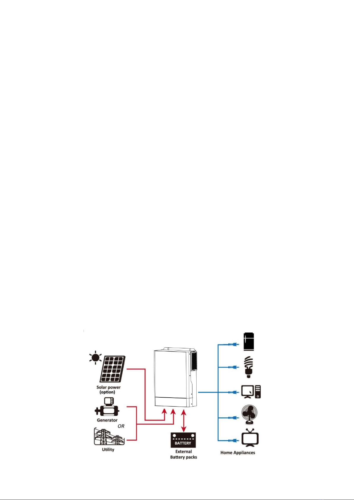
Basic System Architecture ......................................................................................................................2
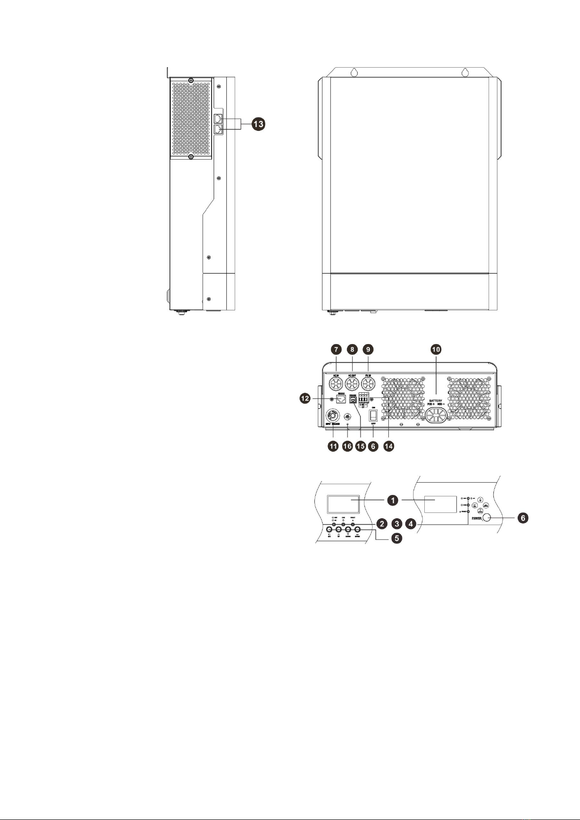
Product Overview ..................................................................................................................................3
INSTALLATION ................................................................................................................................. 4
Unpacking and Inspection ..................................................................................................................... 4
Preparation ...........................................................................................................................................4
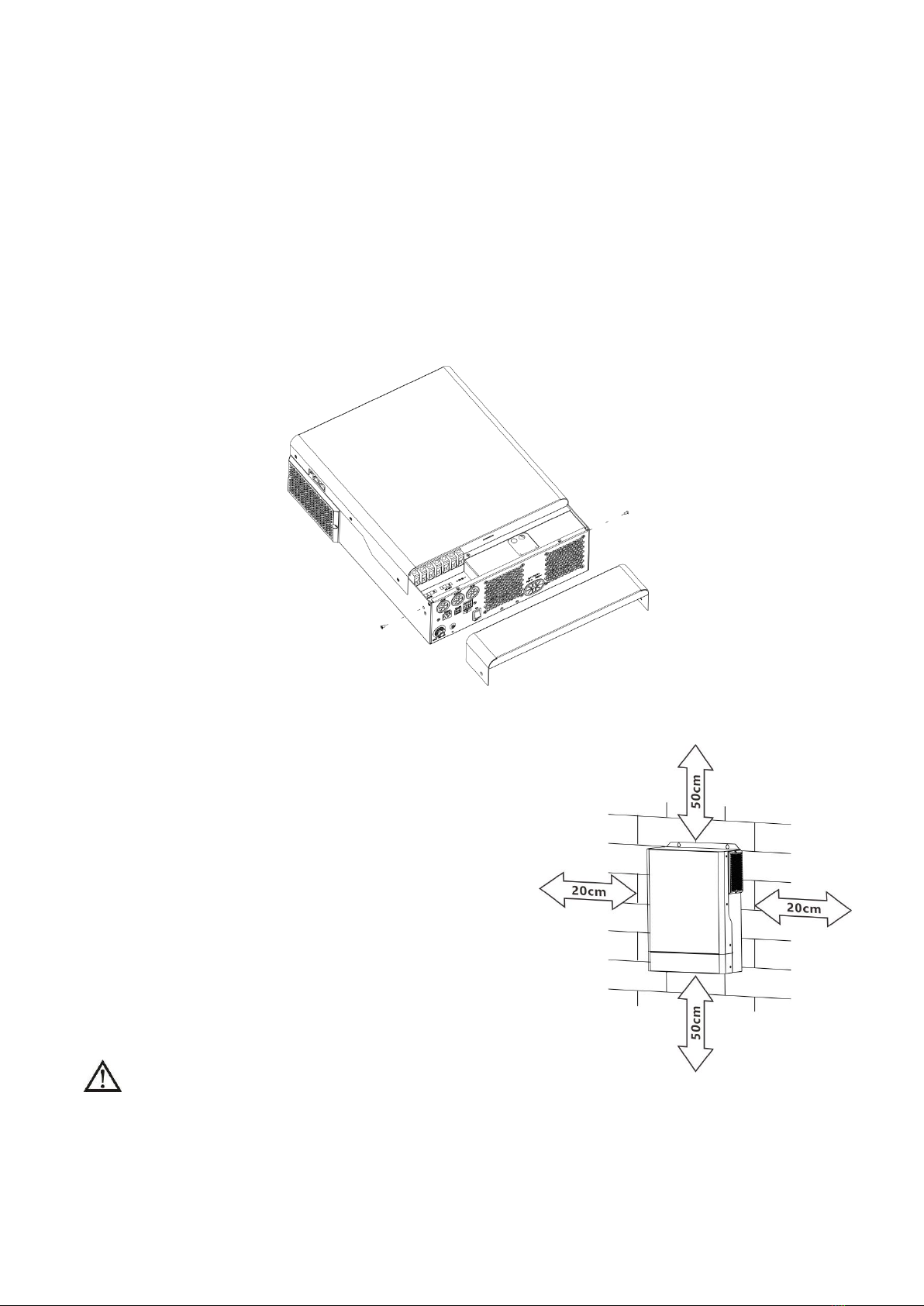
Mounting the Unit ................................................................................................................................. 4
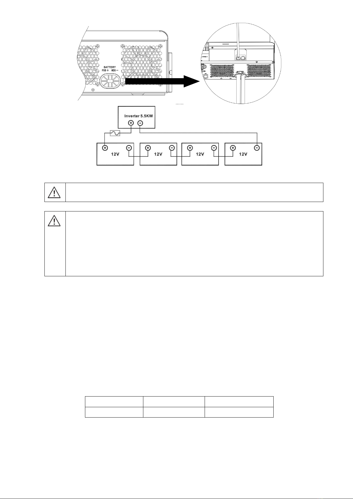
Battery Connection ................................................................................................................................5
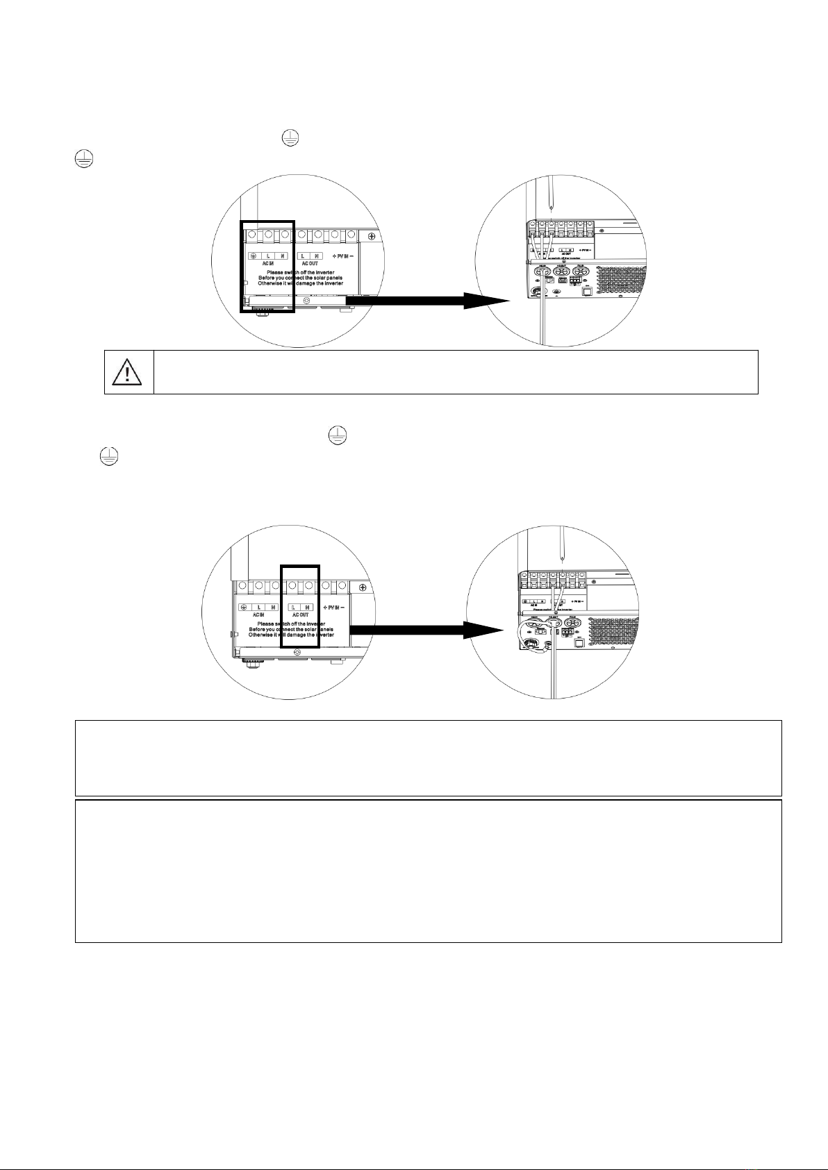
AC Input/Output Connection ..................................................................................................................6
PV Connection ...................................................................................................................................... 8
Final Assembly .................................................................................................................................... 10
OPERATION .................................................................................................................................... 11
Power ON/OFF ....................................................................................................................................11
Operation and Display Panel ................................................................................................................ 11
LCD Display Icons ............................................................................................................................... 12
LCD Setting ........................................................................................................................................ 14
LCD display description ........................................................................................................................23
Operating Mode Description .................................................................................................................26
Fault Reference Code .......................................................................................................................... 30
Warning Indicator ............................................................................................................................... 32
BATTERY EQUALIZATION ...............................................................................................................33
SETTING FOR LITHIUM BATTERY .................................................................................................. 35
SPECIFICATIONS ........................................................................................................................... 38
Table 1 Line Mode Specifications ..........................................................................................................38
Table 2 Inverter Mode Specifications .................................................................................................... 39
Table 3 Charge Mode Specifications ..................................................................................................... 40
Table 4 General Specifications ............................................................................................................. 40
TROUBLE SHOOTING ......................................................................................................................41
Parallel Installation Guide ............................................................................................................. 42
Instruction ..........................................................................................................................................42
Package Contents ................................................................................................................................42
Mounting the Unit ............................................................................................................................... 42
Wiring Connection ...............................................................................................................................43
Parallel Operation in Single phase ........................................................................................................ 45
Support 3-phase equipment .................................................................................................................48
PV Connection .................................................................................................................................... 50
Commissioning ....................................................................................................................................50
Trouble shooting .................................................................................................................................51