Amensolar N3H-A Series User manual

USER MANUAL
N3H-A Series
Three Phase Hybrid Inverter

Copyright Statement
Please keep the manual properly and operate in strict accordance with all safety and operating
instructions in this manual. Please do not operate the system before reading through the
manual.
Contact the nearest hazardous waste disposal station when the products or components are
discarded.

CONTENTS
1. Introduction ...................................................................................... 1
1.1. Preface ....................................................................................1
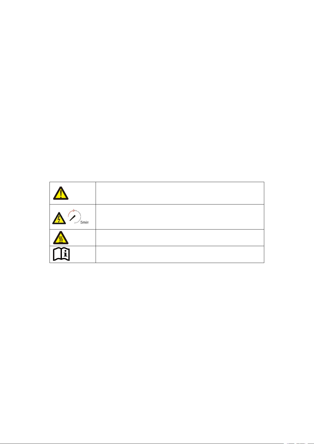
1.2. Safety Introduction ...................................................................... 1
1.3. General Precautions ..................................................................... 3
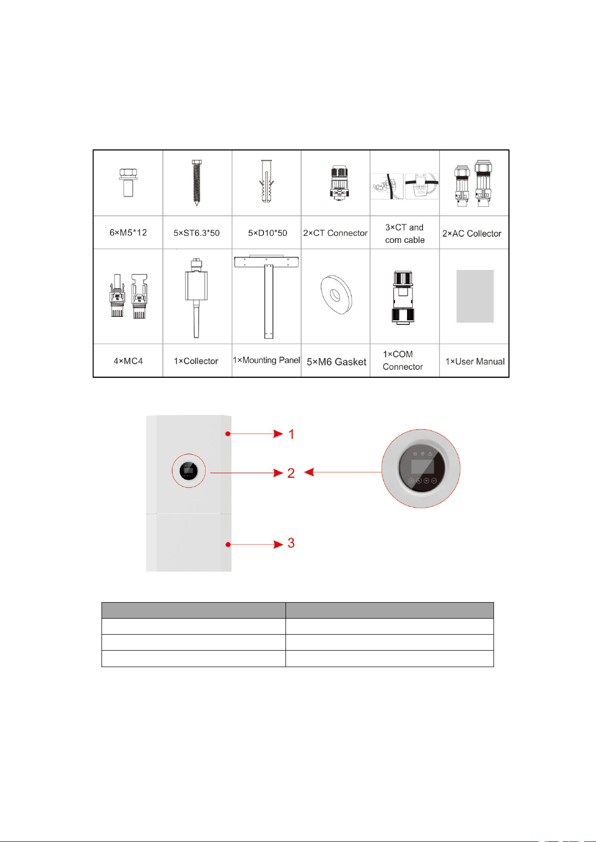
1.4. Parts List ................................................................................. 4
1.5. System Appearance ......................................................................4
1.6. Liability Limitation ...................................................................... 7
2. Installation ....................................................................................... 8
2.1. Installation Site and Environment ...................................................... 8
2.2. Installation ..............................................................................10
2.3. Electric Connection .................................................................... 11
2.4. External CT Connection ............................................................... 15
2.5. DRED Port Connections (optional,only for DRM function) ...................... 16
2.6. COMM Port Connections ............................................................. 17
2.7. METER+DRY Port Connections ..................................................... 17
2.8. Single Line Diagram ................................................................... 19
3. System Operation .............................................................................. 21
3.1. Switch On .............................................................................. 21
3.2. Switch Off .............................................................................. 22
3.3. Emergency Procedure ..................................................................22
4. EMS Introduction And Set Up ................................................................ 23
4.1. Function Description ...................................................................23
4.2. Display and Setting .................................................................... 23
4.2.1. General settings ...................................................................... 23
4.3. Configuration Menus Overview .......................................................26
5. Stick Logger Quick Guide .................................................................... 34
5.1. Download APP ......................................................................... 34
5.2. Stick Logger Installation .............................................................. 34
5.3. Logger Status ...........................................................................34
5.4. Abnormal State Processing ............................................................ 35
5.5. Usage Methods and Notices for Reset Button ........................................36
6. SOLARMAN Smart APP ..................................................................... 38
6.1. Registration .............................................................................38
6.2. Create a Plant ...........................................................................38
6.3. Add a Logger ...........................................................................38
6.4. Network Configuration ................................................................ 39
7. Alarm Code and Error Code .................................................................. 42
7.1. Alarm Code ............................................................................ 42
7.2. Error Code ..............................................................................42
8. Fault Diagnosis and Solutions ................................................................ 44
9. Product Specifications .........................................................................47

1
1. Introduction
1.1. Preface
This product is a hybrid inverter, through which solar energy can be connected and stored in
batteries as well as power the load. It is an intelligent energy product that incorporates both
general needs of customers and industry, and facilitates personalized control.
Solar energy can produce direct current through PV panels, partly of which is then
transformed into DC by inverter to supply batteries for energy storage, while partly converted
into AC to support the load or power grid. Besides, the portion of energy that is converted by
inverter can be wisely manipulated and rationed based on practical needs.
Strict inspection has been made in terms of the manufacturing, packaging as well as
out-of-factory impertinent to products. If there is anything missing, do not hesitate to contact
us or supplier for better solution.
Our company is committed to the constant improvement of inverter, so if the information
offered by the company is altered, no timely notification will be sent.
1.2. Safety Introduction
1.2.1. Manual Keeping
This manual contains important information about operating the system. Before operating,
please read it very carefully. The system should be operated in strict accordance with the
instructions in the manual, otherwise it can cause damages or loss to equipment, personnel
and property. This manual should be kept carefully for maintenance and reparation.

2
1.2.2. Operator Requirements
The operators should get a professional qualification, or be trained.
The operators should be familiar with the whole storage system, including compositions and
working principles of the system.
The operators should be familiar with the Product Instruction.
While maintaining, the maintainer is not allowed to operate any equipment until all the
equipment has been turned off and fully discharged.
1.2.3. Protection of Warning Sign
The warning signs contain important information for the system to operate safely, and it is
strictly prohibited to torn or damage them. Ensure that the warning signs are always
well-functioned and correct placed. The signs must be replaced immediately when damaged.
This sign indicates a hazardous situation which, if not avoided,
could result in death or serious injury!
The H5/H3 must not be touched or put into service until 5 minutes
after it has been switched off or disconnected to prevent an electric
shock or injury.
This sign shows danger of hot surface!
Refer to the operating instructions.
1.2.4. Setting of Warning Sign for Safety
During instruction, maintenance and repair, follow the instructions below to prevent
non-specialist personnel from causing misuse or accident:
Obvious signs should be placed at front switch and rear-level switch to prevent accidents
caused by false switching.
Warning signs or tapes should be set near operating areas.
The system must be reinstalled after maintenance or operation.
1.2.5. Measuring Equipment
To ensure the electrical parameters to match requirements, related measuring equipment are
required when the system is being connected or tested. Ensure that the connection and use
matched specification to prevent electric arcs or shocks.

3
1.2.6. Moisture Protection
It is very likely that moisture may cause damages to the system. Repair or maintaining
activities in wet weather should be avoided or limited.
1.3. General Precautions
DANGER
Danger to life due to high voltages of the PV array, electric shock. When exposed to sunlight,
the PV array generates dangerous DC voltage which will be present in the DC conductors and
the live components of the inverter. Touching the DC conductors or the live components can
lead to lethal electric shocks. If you disconnect the DC connectors from the system under load,
an electric arc may occur leading to electric shock and burns.
Do not touch uninsulated cable ends. Do not touch the DC
Do not open the inverter and battery.
Do not wipe the system with damp cloth.
Have the system installed and commissioned by qualified people with the appropriate
skills only.
Prior to performing any work on the inverter, disconnect the inverter from all voltage
sources as described in this document.
CAUTION
Risk of injury through lifting or dropping the system. The inverter and battery are heavy.
There is risk of injury if the inverter or battery is lifted incorrectly or dropped during transport
or when attaching to or removing from the wall.
Lifting and transporting the inverter and battery must be carried out by more than 2
people.

4
1.4. Parts List
Check the following parts list to ensure it is complete.
Delivers a total system separately on site to client, this consists of:
1.5. System Appearance
Figure 1 N3H-A8.0/10.0/12.0 Delivery Scope
Object
Description
1
Hybrid Inverter
2
EMS Display Screen
3
Cable Box (connected to Inverter)

5
1.5.1. Cable Box Part
Figure 2 Inverter without Cable Box Covers-Front View
Figure 3 Cable Box Part without Covers-Front View
Object
Description
1
Battery circuit breaker
2
Output terminal block(BACK UP)
3
DC isolation switch

6
Figure 4 Cable Box Part without Covers
Object
Description
DVC* class
Object
Description
DVC* class
1
PV1, PV2
DVC C
2
BACKUP
DVC C
3
ON GRID
DVC C
4
DRM OR PARALLEL2
DVC A
5
COM
DVC A
6
METER+DRY
DVC A
7
BAT
DVC A
8
CT
DVC A
9
PARALLEL1
DVC A
Note: The DVC indicates the minimum required level of protection for the circuit.

7
1.6. Liability Limitation
Any product damage or property loss caused by the following conditions, does not assume any
direct or indirect liability.
Product modified, design changed or parts replaced without authorization;
Changes, repair attempts and erasing of series number or seals by non-company technician;
System design and installation are not in compliance with standards and regulations;
Fail to comply with the local safety regulations (VDE for DE, SAA for AU);
Transport damage (including painting scratch caused by rubbing inside packaging during
shipping). A claim should be made directly to shipping or insurance company in this case as
soon as the container/packaging is unloaded and such damage is identified;
Fail to follow any/all of the user manual, the installation guide and the maintenance
regulations;
Improper use or misuse of the device; Insufficient ventilation of the device;
The maintenance procedures relating to the product have not been followed to an acceptable
standard;
Force majeure (violent or stormy weather, lightning, overvoltage, fire etc.); Damages
caused by any external factors.

8
2. Installation
This Manual introduces the basic steps to install and set up.
NOTE:
Please be cautious unpacking the battery, otherwise components
could be damaged.
2.1. Installation Site and Environment
2.1.1. General
This N3H-A8.0/10.0/12.0 energy storage system is outdoor version and can be installed in an
outdoor or an indoor location.
When N3H-A8.0/10.0/12.0 systems are installed in a room, N3H-A8.0/10.0/12.0 must not be
hampered by the structure of the building, the furnishings and equipment of the room.
The N3H-A8.0/10.0/12.0 is naturally ventilated. The location should therefore be clean, dry and
adequately ventilated. The mounting location must allow free access to the unit for installation and
maintenance purposes, and the system panels must not be blocked.
The following locations are not allowed for installation:
Habitable rooms;
Ceiling cavities or wall cavities; on roofs that are not specifically considered suitable; access
/ exit areas or under stairs / access walkways;
Where the freezing point can be reached, such as garages, carports or other places as well as
wet rooms (environmental category 2);
Locations with humidity and condensation over 95%;
Places where salty and humid air can penetrate;
Seismic areas - additional security measures are required;
Sites with altitude over 2000m;
Places with an explosive atmosphere;
Locations with direct sunlight or a large change in the ambient temperature;
Places with flammable materials or gases or an explosive atmosphere.
2.1.2. Restricted Locations
(1) The N3H-A8.0/10.0/12.0 shall not be installed:
(2) in restricted locations as defined for panels in AS / NZS 3000;

9
(3) within 600mm of any heat source, such as hot water unit, gas heater, air conditioning unit or
any other appliance.
(4) within 600mm of any exit;
(5) within 600mm of any window or ventilation opening;
(6) within 600mm of side of other device.
A N3H-A8.0/10.0/12.0 installed in any corridor, hallway, lobby or the like and leading to an
emergency exit shall ensure sufficient clearance for safe egress of at least 1 meter.
The N3H-A8.0/10.0/12.0 must also not be installed in potentially explosive atmospheres for gas
cylinders that are heavier than air gases and have a vent clamp in accordance with AS / NZS 3000.
2.1.3. Barrier to Habitable Rooms
To protect against the spread of fire in living spaces where the N3H-A8.0/10.0/12.0 is mounted or
on surfaces of a wall or structure in living spaces with a N3H-A8.0/10.0/12.0 on the other side, the
wall or structure shall have a suitable non-combustible barrier. If the mounting surface itself is not
made of a suitable non-combustible material, a non-combustible barrier can be placed between the
N3H-A8.0/10.0/12.0 and the surface of a wall or structure.
If the N3H-A8.0/10.0/12.0 is mounted at a wall or at a distance of 300mm from the wall or the
structure separating it from the habitable space, the distances to other structures or objects must be
increased. The following distances must remain free:
600 mm beside the N3H-A8.0/10.0/12.0; 500 mm above the N3H-A8.0/10.0/12.0; 600 mm before
the N3H-A8.0/10.0/12.0.
If the distance between the N3H-A8.0/10.0/12.0 and the ceiling or any object above the system is
less than 500mm, the ceiling or structural surface above the system must be made of
noncombustible material within a radius of 600mm around the system.
The N3H-A8.0/10.0/12.0 must be mounted to ensure the highest point is not more than 2.2m
above the ground or the platform.
Note: A shelter must be installed above the SINERGY

10
Figure 5 Limited Distance of Installation to Neighboring Objects
2.2. Installation
2.2.1. Inverter Installation
(1) Remove the product from the packaging box.
(2) Fix the mounting panel to the wall.

11
(3) Hang the product onto the mounting panels.
(4) Adjust the entire product and ensure that the product has been securely hung onto the panel.
NOTE:
The inverter's built-in residual-current monitoring unit (RCMU)
removes DC residual current above 6mA, so an external RCD (type
A or type B ) can be used with the system (≥30mA).In addition, the
installation of inverter must fulfill AS/NZS 3000, AS/NZS 4777.1
and AS/NZS 5033. The internal N line of converter is connected to
grid neutral via internal relays, when in stand-alone mode.
2.3. Electric Connection
2.3.1. AC Connection
Step 1. Please make AC cables on site.
Step 2. For backup connection, 12AWG or 4mm² cable is required to be used. For grid connection,
10AWG or 6mm² cable is required to be used. Please make sure the resistance of cable is lower
than 1 ohm.
WARNING:
There are"1, 2, 3,N, PE'' symbols marked inside the connector, the
Line wire of grid must be connected to "1, 2, 3" terminal; the Neutral
wire of grid must be connected to "N" terminal; the Earth of grid
must be connected to "PE" .
2.3.1.1. Insert the conductor into the suitable ferrule acc. to DIN 46228-4 and crimp the contact.
Step 1.Strip the protection layer and insulation layer by specific length, as described in the figure

12
below.
When locking the power grid cable into the external power grid connector, the RST should be
marked on the corresponding cable, because when installing the CT, the three CTs with RST
identification need to be buckled on the RST line of the corresponding identification.
Step 2. Make the cable and crimp the terminal.
2.3.1.2. Unscrew the swivel nut from the threaded sleeve and thread the swivel nut and threaded
sleeve over the AC cable.
2.3.1.3. Insert the crimped conductors L, N and PE into the corresponding terminals and tighten
the screw with a hex key wrench screwdriver (size: 2.5, 1.2~2.0 N.M ). Ensure that all conductors
are securely in place in the screw terminals on the bush insert.

13
2.3.1.4. Screw the swivel nut onto the threaded sleeve. This seals the AC connector and provides
strain relief for the AC cable. When doing so, hold the bush insert firmly by the locking cap. This
ensures that the swivel nut can be screwed firmly onto the threaded sleeve.
2.3.1.5. Assembly the plug shell ,adapter as below picture, Push the adapter and Shell by hand
until a “Click” is heard or felt.
2.3.1.6. Plug the AC connector into the jack for the AC connection by hand until a “Click” is
heard or felt.
2.3.1.7. Use tool to clamp the AC wiring terminal and wire rod; screw the nut, but do not tighten
it. Make sure that the cable is free to pass through the waterproof components. Once the terminal
is connected to the right site of the inverter, tighten the nut.
2.3.1.8. Connect the AC wiring terminal to the corresponding hole site of the inverter and lock it
with a screw driver or electric screw driver (suggestion: stem diameters and torsion of screw
driver or electric screwdriver should be 4mm and 8~12kg-f.cm respectively)

14
2.3.1.9. Tighten the nut.
2.3.1.10. Circuit breaker parameters are recommended:
Back-up 25A/400Vac 6KA
On-grid 32A/400Vac 6KA
2.3.2. PV Input Connection
Step 1: Connect the Backup and Grid cables in advance according to the connector mode, and
connect them to the Backup and Grid board connectors in turn.
Figure 6 Cable Box Bottom View, Wiring Connectors
Step 2:Close the battery covers and connect the PV-MC4 connectors to the system (connection
on both sides). Also, connect all AC cables, the meter communications cable METER, and the
Ethernet cable LAN. Then close the cable box cover. The installation is now complete.
Figure 7 PV Wiring

15
Step 3:Close the lid and tighten the screw.
NOTE:
Recommended AC circuit breaker rating is 32A for grid, 25A for
backup.
NOTE:
It is necessary to disconnect the power line, communication line and
communication line between battery pack and inverter to manually
sleep all battery packs.
STATEMENT:
The method of anti-islanding protection is power variation.
2.4. External CT Connection
The electricity meter should be mounted and connected at the grid transition point (feed-in point)
so that it can measure the grid reference and feed-in power.
(1) Loosen the nut, and untangle the single-aperture sealing ring.
Pin
Description
Pin
Description
1
R phase CT positive
electrode(White)
2
R phase CT negative
pole(Black)
3
S phase CT positive
electrode(White)
4
S phase CT negative
pole(Black)
5
T phase CT positive
electrode(White)
6
T phase CT negative
pole(Black)

16
(2) Install the waterproof component and screw on the waterproof sheath nut.
(3) Open the external CT wiring port, the arrow points to the direction of the power grid, put the
wire into the external CT card slot, and buckle the buckle.
NOTE:
CT should be placed near the power grid.
If CT test pass but inverter still can't achieve export power (power is
not controllable or always 0 power output).Please check installation
location of the CT.
2.5. DRED Port Connections (optional,only for DRM function)
DRED means demand response enable device. The AS/NZS 4777.2:2015 required inverter need to
support demand response mode (DRM). This function is for inverter that comply with AS/NZS
4777.2:2015 standard. Inverter is fully comply with all DRM. A 8P terminal is used for DRM
connection.
PIN
PIN Name
Description
Connected to RRCR
1
G
GND
Not connected
2
V
5VDC Voltage Supply
Relays common node
3
DRM4/8
Relay contact 4 input
K4-Relay 4 output
4
V
5VDC Voltage Supply
Relays common node
5
DRM3/7
Relay contact 3 input
K3-Relay 3 output
6
DRM2/6
Relay contact 2 input
K2-Relay 2 output
7
DRM1/5
Relay contact 1 input
K1-Relay 1 output
8
DRM0
Relay contact 0 input
K0-Relay 0 output
The inverter is preconfigured to the following RRCR power levels.
DRM0
DRM1/5
DRM2/6
DRM3/7
DRM4/8
Active
Power
Cos(Q)
1
0
1
1
1
0%
1
1
1
0
1
1
30%
1
1
1
1
0
1
60%
1
1
1
1
1
0
100%
1
1
1
1
1
1
100%
1
0
X
X
X
X
Standby
1

17
Figure 8 DRM connector
2.6. COMM Port Connections
PIN
Description
1
+5V
2
GND
3
RS485-A
4
RS485-B
2.7. METER+DRY Port Connections
Note:
(1) The Smart Meter (ADW300W or SDM630MCT are suggested.) with CT is already
configured; please do not change any settings on the Smart Meter.
(2) One Smart Meter can be used with only one inverter.
(3) Three CTs must be used for one Smart Meter and must be connected on the same phase with
the Smart Meter power cable.
This manual suits for next models
3
Table of contents
Other Amensolar Inverter manuals
Popular Inverter manuals by other brands

Mitsubishi Electric
Mitsubishi Electric FR-C500 instruction manual

Adler Power
Adler Power CO-SinusUPS-400W user manual

Southwest Windpower
Southwest Windpower AIR 30 owner's manual

SunReports
SunReports Apollo1 installation manual

Energenie
Energenie EG-PWC-PS1000-01 instructions

Omron
Omron SX-F instruction manual