Page 2 of 2©2022 American Lighting, Inc. REV2246 www.AmericanLighting.com 11775 E. 45th Ave. Denver, CO 80239 Ph: 1-800-880-1180 Fax: 303-695-7633
SPEKTRUM+ NEON - RGBW12V AC
INSTALLATION INSTRUCTIONS
SPKPL-NFL-RGBW-12VAC-6MKIT Series
Page 2 of 2 11775 E. 45th Ave. Denver, CO 80239 Ph: 1-800-880-1180 Fax: 303-695-7633
INSTALLING 12V AC NEON:
Disconnect power at the source prior to attempting installation or
service of product. Use this fixture with included power cable and 12V
AC rectifier only. Any other power feed may damage the fixture.
1. Determine the desired locations and lengths of 12V AC Neon, as well
as the location for the RF receiver and 12V AC rectifier, to be
installed. Use this information to determine locations and sizes of 12V
DC power supplies (sold separately).
2. Install mounting clips or aluminum channel (NFPROL-FCHAN-1M) by
screwing into a solid, sturdy surface. See Figure 2. Mounting clips
should be evenly spaced and a maximum of 3 feet apart. Two parallel
lines of 12V AC Neon must be at least 1/2” apart.
3. Gently push the 12V AC Neon into the mounting clips or channel
starting at the beginning of the run and moving down the line towards
the end. Leave enough room for the power cable to reach the power
supply. End caps cannot be installed within the aluminum channel.
See Figure 3. Ensure the NeoFlux does not sag and does not bend
more than the maximum bend radius of 24cm at any point.
4. Connect the RF Receiver to the beginning of the 12V AC Neon run
using the preinstalled power cable. See Figure 4.
5. Connect the 12V DC power supply to line voltage and then connect
to 12V AC rectifier using bare wire lead.
6. Reconnect power at source.
FIGURE 2
FIGURE 4
FIGURE 3
Mounting Surface
Aluminum Extrusion
The end cap cannot be installed
into the aluminum extrusion
CUTTING 12V AC NEON:
Disconnect power at the source prior to attempting installation or
service of product.
1. Determine the location of the cut based on the cutting increments
marked on the bottom of the 12V AC Neon (31.25mm or 1.23”).
2. Using an appropriate utility blade, gently cut straight down through
the 12V AC Neon directly on the cutting increment mark. Do not use
scissors or bolt cutters. Do not cut diagonally or horizontally as this
may damage the product. See Figure 5.
3. Seal cut-end using included end cap and an appropriately rated
silicone or Silicone glue (not included). See Figure 6.
FIGURE 5
FIGURE 6 Silicone Glue
GLUE
Cut along the cut-mark on the
backside of the NeoFlux
FCC Compliance Statement
This device complies with part 15 of the FCC Rules. Operation is subject to the following two conditions:
1. This device may not cause harmful interference, and
2. This device must accept any interference received, including interference that may cause undesired operation.
FCC WARNING
This equipment has been tested and found to comply with the limits for a Class B digital device, pursuant to Part 15 of the FCC Rules. These limits are designed to provide reasonable
protection against harmful interference in a residential installation. This equipment generates, uses and can radiate radio frequency energy and, if not installed and used in accordance with
the instructions, may cause harmful interference to radio communications. However, there is no guarantee that interference will not occur in a particular installation. If this equipment does
cause harmful interference to radio or television reception, which can be determined by turning the equipment o and on, the user is encouraged to try to correct the interference by one or
more of the following measures:
• Reorient or relocate the receiving antenna.
• Increase the separation between the equipment and the receiver.
• Connect the equipment into an outlet dierent from that to which the receiver is connected.
• Consult the dealer or an experienced radio/TV technician for help. Changes or modifications not expressly approved by the party responsible for compliance could void the user’s authority
to operate the equipment.
Any changes or modifications not expressly approved by the party responsible for compliance could void the user’s authority to operate the equipment.
CONTROLLING THE TAPE LIGHT: The in-line LED controller/receiver utilizes
Bluetooth® Wireless Technology and can be controlled via the Spektrum+ Smart
Lighting App. It is not intended to be used with a standard dimmer switch.
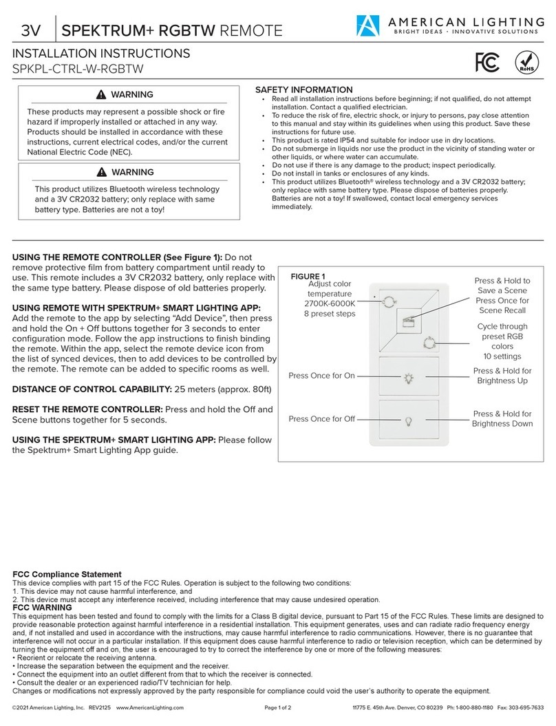
USING THE REMOTE CONTROLLER (See Figure 10): Do not remove protective
film from battery compartment until ready to use. This remote includes a
3V CR2032 battery, only replace with the same type battery. Please dispose of
old batteries properly.
USING REMOTE WITH SPEKTRUM+ SMART LIGHTING APP: Add the remote to
the app by selecting “Add Device”, then pressing and holding the On + O button
together for 3 seconds to enter configuration mode. Follow the app instructions to
finish binding the remote. Within the app, select the remote to add devices to be
controlled by the remote. The remote can be added to specific rooms as well.
DISTANCE OF CONTROL CAPABILITY: 25 meters (approx. 80ft)
RESET THE REMOTE CONTROLLER: Press and hold O and Scene buttons
together for 5 seconds.
USING THE SPEKTRUM+ SMART LIGHTING APP: Please follow the Spektrum+
Smart Lighting App guide.
FIGURE 10
Press for On
Press for O
Cycle through 10
preset RGB colors
Press & Hold to
Save a Scene
Press for Scene
Recall
Set color
temperature to
3000K White
Press & Hold for
Brightness Up
Press & Hold for
Brightness Down


