American Standard TCM030F1 Owner's manual

All phases of this installation must comply with the NATIONAL, STATE & LOCAL CODES. In the absence of local codes, the installa-
tion must conform with National Electric Code -- ANSI/NFPA 70 or “LATEST REVISION.”
Dwg. No. X730377 P02
18-AB33D2-3
INSTALLATION
OPERATION
MAINTENANCE
IMPORTANT — This Document is customer property and is to remain with this unit. Please return to service information pack upon completion of work.
Manufactured Housing
Package Cooling
W/ Optional Electric Heat
2-1/2 - 4 Ton
Model:
TCM030F1
TCM036F1
TCM042F1
TCM048F1
HAZARDOUS VOLTAGE - DISCONNECT POWER BEFORE SERVICING
WARNING:
© 2001 American Standard Inc. All rights reserved
Since the manufacturer has a policy of continuous product and product data improvement,
it reserves the right to change design and specification without notice.

Page 2 Dwg. No. X730377 P02
Read this manual carefully before attempting to install, operate, or
perform maintenance on this unit. Installation and maintenance
should be performed by qualified service technicians only.
NOTE: “Warnings” and “Cautions” appear at appropriate
places in this manual. Your personal safety and the proper
operation of this air conditioning product require that you follow
them carefully. The manufacturer assumes no liability for
installations or servicing performed by unqualified personnel.
INSPECTION
1. Check for damage after the unit is unloaded. Report promptly,
to the carrier, any damage found to the unit. Do not drop the unit.
IMPORTANT: The use of “spreader bars”is required when
hoisting the unit (to prevent damage to sides and top).
2. Check the unit’s nameplate to determine if the unit is correct for
the intended application. The power supply must be adequate
for both the unit and all accessories.
3. Check to be sure the refrigerant charge has been retained during
shipment.
GENERAL INFORMATION
IMPORTANT: RECONNECT ALL GROUNDING DEVICES.
ALL PARTS OF THIS PRODUCT CAPABLE OF CONDUCTING
ELECTRICAL CURRENT ARE GROUNDED. IF GROUNDING
WIRES, SCREWS, STRAPS, CLIPS, NUTS OR WASHERS
USED TO COMPLETE A PATH TO GROUND ARE REMOVED
FOR SERVICE, THEY MUST BE RETURNED TO THEIR ORIGI-
NAL POSITION AND PROPERLY FASTENED.
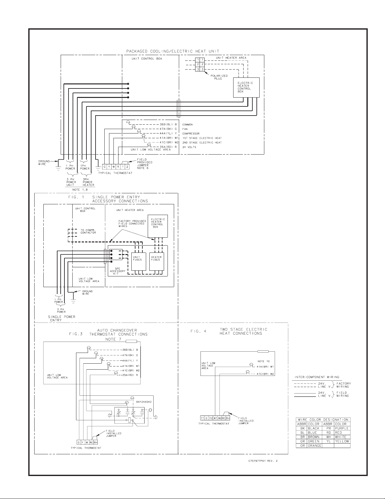
IMPORTANT: ALL POWER LEGS MAY NOT BE BROKEN BY
CONTACTORS. SEE WIRING DIAGRAM ON UNIT CONTROL
BOX COVER.
BEFORE STARTING THE COMPRESSOR, THE CRANKCASE
HEATER SHOULD BE ENERGIZED FOR EIGHT HOURS.
SAFETY NOTICE. THIS INFORMATION IS INTENDED FOR
USE BY INDIVIDUALS POSSESSING ADEQUATE BACK-
GROUNDS OF ELECTRICAL AND MECHANICAL EXPERI-
ENCE. ANY ATTEMPT TO REPAIR A CENTRAL AIR CONDI-
TIONING PRODUCT MAY RESULT IN PERSONAL INJURY
AND/OR PROPERTY DAMAGE. THE MANUFACTURER OR
SELLER CANNOT BE RESPONSIBLE FOR THE INTERPRE-
TATION OF THIS INFORMATION, NOR CAN IT ASSUME
LIABILITY IN CONNECTION WITH ITS USE.
IMPORTANT: Read this entire manual before beginning instal-
lation procedures.
These units are designed for outdoor installation. For proper instal-
lation, the following recommendations must be considered.
Select a location that will permit unobstructed airflow into the
condenser coil and away from the fan discharge and permit unob-
structed service access into the compressor compartment. Sug-
gested airflow clearances and service clearances are given in
Figure 2.
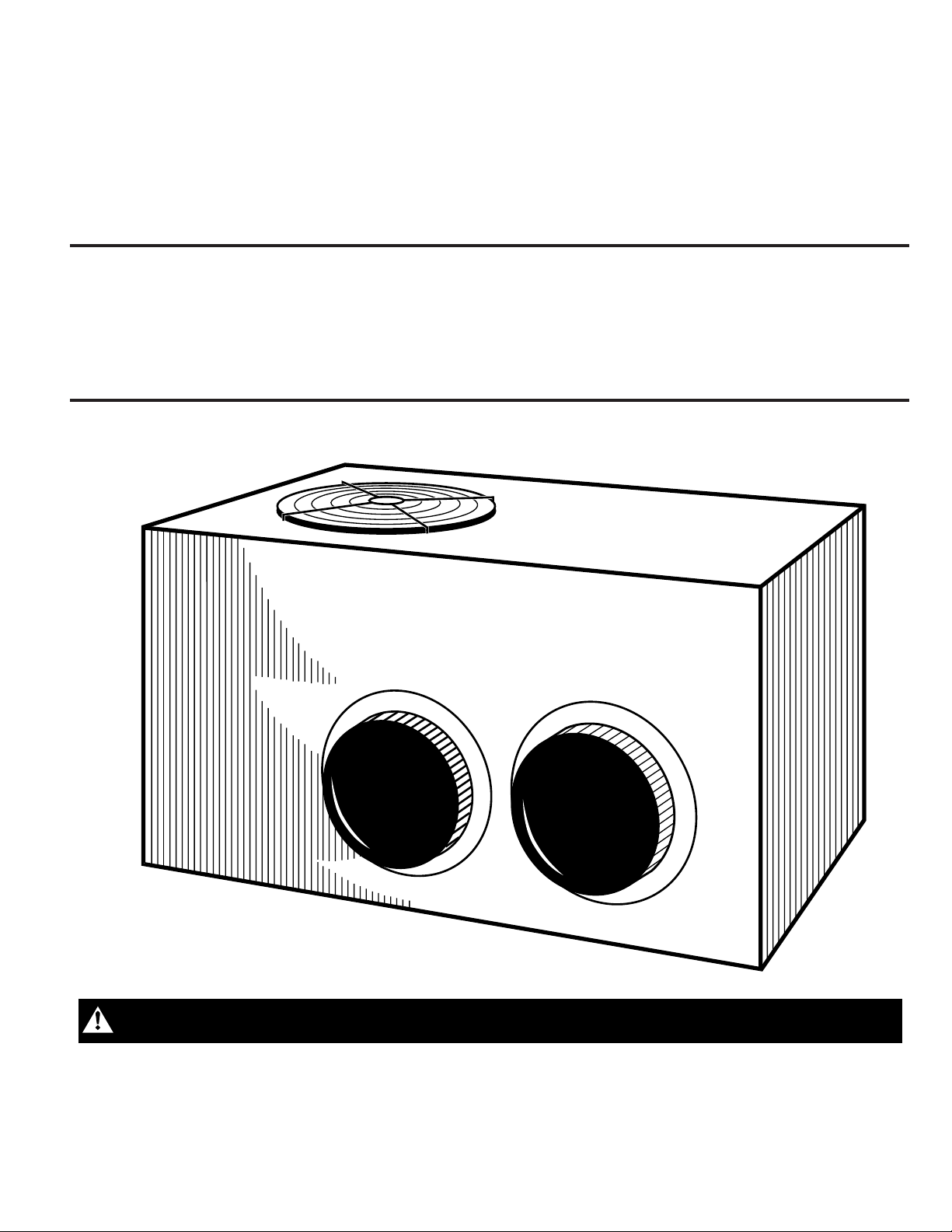
NOTE: Unit shipped for horizontal installation.
The discharge air from the condenser fans must be unrestricted for
a minimum of 3 feet above the unit.
NOTE: If any internal accessories are to be added to the unit it
should be done at the shop if at all practical.
1. Unit should be positioned so Roof-Run-Off water does not pour
directly on unit.
2. Exhaust vents or other sources of contaminated air should not
be near unit air inlet if outside air is to be introduced as a make-
up air or the economizer ventilation feature is to be used.
3. Check the handling facilities to insure the safety of personnel and
the unit(s).
4. CAUTION MUST BE TAKEN AT ALL TIMES TO AVOID PER-
SONAL INJURIES AND/OR DAMAGE TO EQUIPMENT.
5. The unit must be mounted level for proper drainage of defrost
water through the holes in the base pan.
6. Flexible duct connectors must be of a flame retardant material. All
duct work outside of the structure must be insulated and weath-
erproofed in accordance with local codes.
7. Holes through exterior walls must be sealed in accordance with
local codes.
8. Access and service clearances for the unit must be given careful
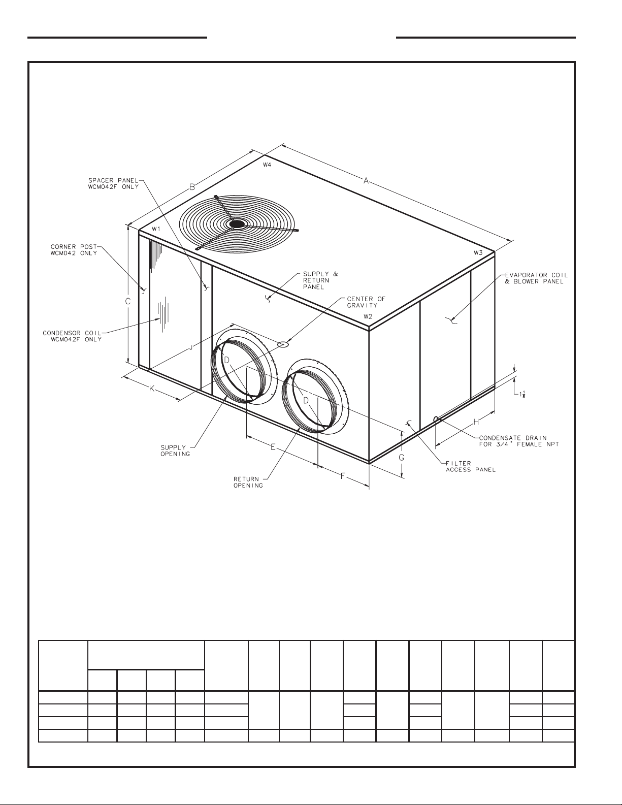
consideration when locating the duct entrance openings. Fig-
ures 1 and 2 provide unit dimensions.
9. All fabricated outdoor ducts should be as short as possible.
10. Be sure the hole in the structure for the ducts is large enough to
accommodate the fabricated ducts and the insulation surrounding
them.
CLEARANCES
1. The recommended clearances for single-unit installations are
illustrated in Figures 1 and 2. These minimum requirements are not
only an important consideration when determining unit placement,
but they are also essential to ensure adequate serviceability,
maximum capacity, and peak operating efficiency.
2. Any reduction of the unit clearances indicated in this illustration
may result in condenser coil starvation, or the recirculation of warm
condenser air.
LOCATIONS AND RECOMMENDATIONS

Dwg. No. X730377 P02 Page 3
Check unit nameplate for supply voltage required. Determine if
adequate electrical power is available. Refer to specification sheet.
GROUND LEVEL -- HORIZONTAL UNITS
For ground level installations, the unit should be positioned on a pad
the size of the unit or larger. The unit must be level on the pad. The
pad must not come in contact with the structure. Be sure the outdoor
portion of the supply and return air ducts are as short as possible.
Proceed with the installation as follows:
INSTALLATION
1. Place the unit on the pad and the five (5) rubber isolators
provided.
2. Attach the supply and return air ducts to the unit.
3. Insulate any ductwork outside of the structure with at least 2
inches of insulation and weatherproof. There must be a weath-
erproof seal where the duct enters the structure.
4. Complete the installation according to the instructions in the
following sections of this manual.
DUCTWORK
ATTACHING HORIZONTAL DUCTWORK
TO UNIT
All conditioned air ductwork should be insulated to minimize heating
and cooling duct losses. Use a minimum of two (2) inches of
insulation with a vapor barrier. The outside ductwork must be
weatherproofed between the unit and the building.
When attaching ductwork to a horizontal unit, provide a flexible
watertight connection to prevent noise transmission from the unit to
the ducts. The flexible connection must be indoors and made out
of heavy canvas.
NOTE: Do not draw the canvas taut between the solid ducts.
FILTER INSTALLATION
AIR FILTERS
Filters are to be used with the TCM030-048F heating/cooling units.
The basic unit does not have filters in it. However, a filter frame
accessory is offered that will allow filters to be installed within the
unit.
Otherwise a filter rack must be installed by the installer in the duct
work.
Affix the filter label supplied with the unit adjacent to the filter area.
TABLE 1
* Filters must be installed in the return air system. The above square
footages are based on 300 F.P.M. face velocity. If permanent filters are
used, size per mfg. recommendation with clear resistance of 0.05" WC.
TINU LANIMON
MFC
*RETLIF
EZIS)tFqS(
RETLIF
ECNATSISER
F030MCT000133.350.0
F630MCT002100.450.0
F240MCT004176.450.0
F840MCT006133.550.0
CONDENSATE DRAIN PIPING
3
/
4
" PVC OR COPPER
TUBING AND FITTINGS
1-1/2" MIN.
A 3/4-inch female NPT condensate drain connection is provided on
the evaporator access panel end of the unit. See Figure 4. Provide
a trap and fill it with water before starting the unit to avoid air from
being drawn through. Follow local codes and standard piping
practices when running the drain line. Pitch the line downward away
from the unit. Avoid long horizontal runs. See Figure 3.
NOTE: Do not use reducing fittings in the drain lines. The conden-
sate drain must be:
●Made of 3/4" pipe size.
●Pitched 1/4" per foot to provide free drainage to convenient drain
system.
●Trapped.
●Must not be connected to closed drain system.
➂

Page 4 Dwg. No. X730377 P02
TCC030-048F OUTLINE - FRONT
DIMENSIONAL DATA
➀
LEDOM
)SBL(THGIEWRENROC TINU
THGIEWTHGIEW THGIEW THGIEWTHGIEW ABCDEFGHJK
1W2W3W4W
F030MCT57462879813
4/1-556361/3-92
21
8/1-71
61/5-21
61/1-0171
61/3-0261/5-52
F630MCT292777990432161/5-218/5-8161/3-42
F240MCT1917972013434161/3-119142
F840MCT3927184010534/3-266361/3-92414/3-2261/5-2161/1-01719142

Dwg. No. X730377 P02 Page 5
DIMENSIONAL DATA
➁
729945
LEDOM ABC D E F
F030MCT
F630MCT
F240MCT
4/1-556361/3-9261/51-218/7-4
TIUDNOC"4/1-1DNA"4/3ROFSTUOKCONK
F840MCT4/3-266361/3-922/1-418/7-4
TCC030-048F OUTLINE - REAR
ECNARAELCECIVRESDEDNEMMOCER
KCAB"0.6
EDISTFEL"0.03
EDISTHGIR"0.42
EDISTNORF"0.03
This manual suits for next models
3
Table of contents
Other American Standard Electric Heater manuals