American Standard HPWH50G-AS User manual

OWNER’S AND OPERATION
MANUAL
Before using your unit, please carefully this
manual and keep it for future reference.
Please ask a certified electrician to install a reliable earth connection. Refer to page 1 .
Your safety is important to us!
WARNING THIS UNIT REQUIRES EARTH CONNECTION. MAKE SURE THERE IS A RELIABLE CONNECTION BEFORE USAGE;
OTHERWISE IT MAY CAUSE DEATH OR INJURY.
HPWH50G-AS
Residential Electric Heat
Pump Water Heater

NOTE: All the pictures in this manual are for explanation purposes only. They may be slightly different from the
heat pump water heater you purchased (depending on the model). The actual shape shall remain consistent.
PARTS NAMES
(Upper)
Top Cover
Filter
Rear Shroud
Evaporator
Temperature
& Pressure
Relief Valve
Water Outlet
Water Inlet
Upper Heating Element
Drain valve
Lower heating
element
Cover, Electric
(Lower)
Front Decorative
Board
Cover, Electric
(Upper)
TCO
T2
Display
Front Shroud
Fan Assembly
Electronic Control
Box
2
HEAT PUMP WATER HEATER

NOTE: Households with small children, disabled or elderly persons may require a 120°F or lower thermostat
setting to prevent contact with HOT water.
CONTENTS
Safety Information 2-3
Operating Instructions 4-10
Care and Cleaning 11-12
Troubleshooting Tips 13-25
IMPORTANT SAFETY INFORMATION.
READ ALL INSTRUCTIONS BEFORE USING.
For your safety, the information in this manual must be followed to minimize the risk of
re or explosion, electric shock, or to prevent property damage, personal injury, or death.
Be sure to read and understand the entire Owner’s Manual before attempting to install or
operate this water heater. It may save you time and money. Pay particular attention to the
Safety Instructions. Failure to follow these warnings could result in serious personal injury
or death. If you have problems understanding the instructions in this manual, or have any
questions, STOP and get help from a qualied technician or the local electric utility.
WARNING
WATERTEMPERATURE ADJUSTMENT
Safety and energy conservation are factors to be considered when selecting the water temperature setting via the
water heater’s user interface. Water temperatures above 120°F can cause severe burns or death from scalding.
Be sure to read and follow the warnings outlined on the label pictured below. This label is also located on the water
heater near the top of the tank.
Water temperature over 120ºF can cause severe burns instantly or death from scalds.
The electronic temperature control setting usually approximates tap water temperature
to reach 160ºF regardless of the control setting. Always feel water before bathing and
showering.
Children, disabled, and elderly are at highest risk of being scalded.
See instruction manual before setting temperature.
Feel water before bathing or showering.
Temperature limiting valves are available. See manual.
Mixing valves for reducing point-of-use water temperature by mixing hot and cold wa-
ter in branch water lines are available. Contact a licensed plumber or the local plumbing
authority for further information.
DANGER
Temperature Time to produce a serious burn
120°F More than 5 minutes
140°F Less than 5 seconds
130°F About 30 seconds
150°F About 1-1/2 seconds
125°F 1-1/2 to 2 minutes
145°F Less than 3 seconds
135°F About 10 seconds
155°F About 1 second
Table courtesy of Shriners Burn Institute 3

FOR INSTALLATIONS INTHE STATE OF CALIFORNIA
OPERATINGTHE WATER HEATER
SAVETHESE INSTRUCTIONS
The chart shown above may be used as a guide in determining the proper water temperature for your home.
California Law requires that residential water heaters must be braced, anchored or strapped to resist falling or hori-
zontal displacement due to earthquake motions.For residential water heaters up to 52 gallon capacity, a brochure with
generic earthquake bracing instructions can be obtained from: Ofce of the State Architect, 400 P Street, Sacramento,
CA 95814 or you may call 916.324.5315 or ask a water heater dealer.
However, applicable local codes shall govern installation. For residential water heaters of a capacity greater than 52
gallons, consult the local building jurisdiction for acceptable bracing procedures.
California Proposition 65 Warning:This product contains chemicals known to the State of California to cause cancer,
birth defects or other reproductive harm.
SAFETY PRECAUTIONS
A.Turn off power to water heater if it has been subjected to overheating, fire, flood or physical damage.
B.Do not turn on the water heater unless it is filled with water.
C.Do not turn on the water heater if cold water supply shut-off valve is closed.
D.Do not store or use gasoline or other flammable vapors and liquids, such as adhesives or paint thinner, in the vicinity
of this or any other appliance. If such flammables must be used, open doors and windows for ventilation.
E. If there is any difculty in understanding or following the Operating Instructions or the Care and Cleaning section,
it is recommended that a qualied person or serviceman perform the work.
NOTE: Households with small children, disabled or elderly persons may require a 120°F or lower thermostat
setting to prevent contact with HOT water.
NOTE: Air currents may draw ammable vapors from surrounding areas to the water heater.
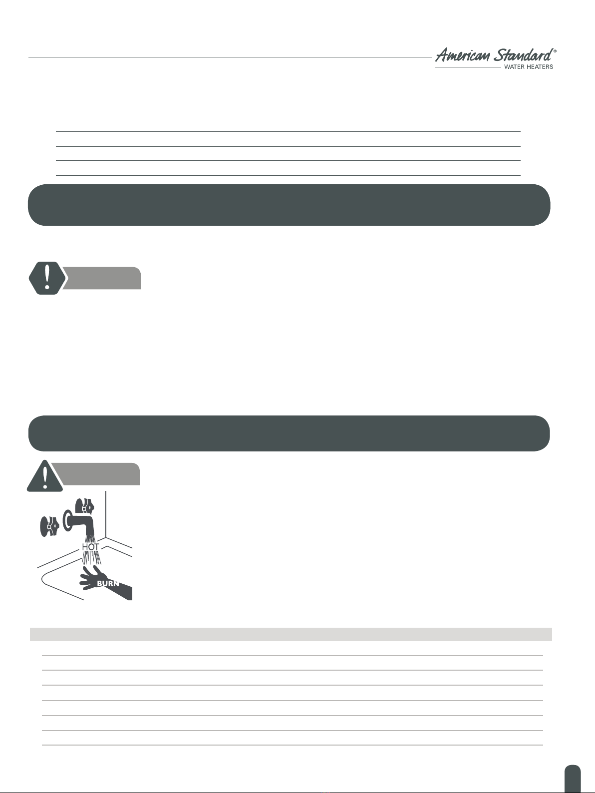
There is a Hot Water SCALD Potential if the control water temperature is set too
high.
DANGER
Gasoline, as well as other ammable materials and liquids (adhesives, solvents, etc.),
and the vapors they produce are extremely dangerous. DO NOT handle, use or
store gasoline or other ammable or combustible materials anywhere near or in
the vicinity of a water heater.The arc drawn in the water heater controls can ignite
these vapors. Failure to do so can result in property damage, bodily injury or death.
WARNING
Hydrogen gas can be produced in a hot water system served by this water heater
that has not been used for a long period of time (generally two weeks or more).
HYDROGEN GAS IS EXTREMELY FLAMMABLE!! To dissipate such gas and to
reduce risk of injury, it is recommended that the hot water faucet be opened for
several minutes at the kitchen sink before using any electrical appliance connected
to the hot water system. If hydrogen is present, there will be an unusual sound such
as air escaping through the pipe as the water begins to ow. Do not smoke or use
an open ame near the faucet at the time it is open.
WARNING
4
HEAT PUMP WATER HEATER

If the water heater has been subjected to flood, fire, or physical damage, turn off power
and water supplies to the water heater.
Do not operate the water heater again until it has been thoroughly inspected by a
qualified service technician.
SAFETY CONTROLS
The water heater is equipped with two temperature-limiting controls (TCO and TOD) that are located above the
heating element in contact with the tank surface. If for any reason the temperature becomes excessively high, the tem-
perature-limiting control (TCO or TOD) breaks the power circuit to the heating element. Once the control opens, it
must be reset manually. A qualied service technician should reset the temperature limiting controls.
READ AND FOLLOWTHIS SAFETY INFORMATION CAREFULLY. SAVE THESE INSTRUCTIONS.
Display
Up
Use up arrow to increase value or turn page up
Power Indicator Light
An illuminated display light indicates that the unit is operating, no light displayed means that the unit has stopped
operating, and a flashing display light means that the unit is in error or under protection.
Power
For starting or shutting down the unit, please note; when the unit is stand-by, the power function can still be
utilized.
Vacation
Use this button during times of no water usage, such as vacation for an extended period of time.
Down
Use Down arrow to decrease the value or turn page down.
Enter
To confirm or unlock the key. After changing the set point temperature through keys, consumer needs to press
this key within 10 seconds to confirm, or else the set point temperature can not change. When the panel is
locked, consumer can press this key for 3 seconds to deactivate the lock.
Mode
Used to select operating mode, auto mode, economic mode & electric mode.
WARNING
CONTROLS
A qualified service technician must investigate the cause of the high temperature
condition and corrective action must be taken before placing water heater in
service again.
To reset the temperature-limiting control:
1.Turn off the power to the water heater.
2.Remove the jacket access panel(s) and insulation.
The thermostat protective cover should not be removed.
3.Press the red RESET button.
4.Replace the insulation and jacket access panel(s) before turning on the power to
the water heater.
CAUTION
2
1
3
4
5
6
8
7
1
2
3
4
5
6
7
8
5

HEAT PUMP WATER HEATER
. uto on r unct on
seconds the pad and no other
. utoloc unct on
. uer unct on
. creen aver
TURNING ON THE WATER HEATER
1
7
8
9
2 3 4 5 6
1011
ea oad h t ng ode
ea oad h t ng ode 2
110°F.
gh e perature ett ng
120°F,
120°F
oc con
lar con
acat on
Use Down arrow to decrease the value or turn page down.
6

7 Auto Mode Icon
This icon will be illuminated when the unit is on auto mode and will be darkened when the unit is not operating
on auto mode.
8 Economic Mode Icon
This icon will be illuminated when the unit is on economic mode and will be darkened when the unit is not
on economic mode..
9Electric Mode Icon
This icon will be illuminated when the unit is on electric heat mode.
10 WaterTemperature Icon
There are 3 phases:
When operating at 140°F≥TS≥120°F, all 3 phases will be illuminated. When operating at 120°F≥TS≥110°F, the
lower 2 phases will be illuminated.
When operating at 110°F≥TS≥100°F, the lowest phase will be illuminated. Note: TS is the preset water
temperature.
11 Parameter Icon
This icon will be illuminated when a power supply is connected. Normally it will show water temperature,
however when there is error or protection, it will show an error code or protection code. When the error
or protection stops, the temperature will display again normally.
NOTE: When the unit is on auto mode this icon will flash slowly.
NOTE: When the unit is on economic mode, this icon will flash slowly.
NOTE: When the unit is on electric heat mode this icon will flash slowly.
7

ABOUTTHE WATERTEMPERATURE SETTING
TIMES & TEMPERATURES THAT MAY CAUSE SCALDING:
The temperature of the water in the water heater can be regulated by adjusting the temperature setting up or down
using arrow keys on the control panel.
Safety and energy conservation are factors to be considered when selecting the water temperature setting of the
water heater.The lower the temperature setting, the greater the savings in energy and operating costs.To comply with
safety regulations, the water temperature is factory set at 120°F where local codes require.This is the recommended
starting point.
Water temperatures above 120°F can cause severe burns or death from scalding. Be sure to read and follow the
warnings outlined in this manual and on the label on the water heater.This label is located on the water heater near
the upper element access panel.
Mixing valves for reducing point-of-use water temperature by mixing hot and cold water in branch water lines are
available. Contact a licensed plumber or the local plumbing authority for further information.
The chart below may be used as a guide in determining the proper water temperature for your home.
TO ADJUSTTHETEMPERATURE
Press the “UP” or “DOWN” key on the control panel. Then the temperature can be increased or decreased. After
the desired temperature setting has been achieved, please press the “ENTER” key to accept this set point. (If you do
not press the “ENTER” key within 10 seconds, the setting will not change.)
There is a hot water scald potential if the water temperature is set too high.
Households with children, disabled, or elderly persons may require a 120°F or
lower thermostat setting to prevent contact with HOT water.
There is hot water scald potential if the water temperature is set too high. 120°F
is the recommended water temperature setting, but it can be adjusted to any
temperature between 100°F and 140°F.
DANGER
DANGER
120°F More than 5 minutes
140°F Less than 5 seconds
130°F About 30 seconds
150°F About 1-1/2 seconds
125°F 1-1/2 to 2 minutes
145°F Less than 3 seconds
135°F About 10 seconds
155°F About 1 second
Table courtesy of Shriners Burn Institute
8
HEAT PUMP WATER HEATER

ADJUSTINGTHE WATERTEMPERATURE AND FUNCTION MODE
This water heater defaults to the Hybrid operating mode.The Hybrid mode is the recommended setting for this water
heater, but can be changed if desired.
Eco Mode
Eco is the most energy-efficient mode for this water heater. It takes heat from the surrounding air to heat the water.
The time it takes to heat the water is longer in this mode, so it may NOT be ideal if you have a high-demand situ-
ation such as a large household or company.
Electric Mode
This mode uses only the upper and lower heating resistance elements to heat the water.The time it takes to heat the
water is reduced in this mode, but it is the LEAST energy-efficient mode.
Auto Mode —RECOMMENDED MODE
Hybrid Mode combines the energy efciency of eHeat™ with the recovery speed and power of the Standard Electric
mode, with normal water usage.
ABOUTTHE FEATURE BUTTONS ONTHE USER INTERFACE
Vacation
You may use this feature when traveling away from home for an extended period of time and hot water won’t be
needed. In this mode, the unit will drop the water temperature down to 50ºF and will use the most efficient heating
mode to conserve energy while the heater is sitting idle. The unit will automatically resume heating one day before
your return, so that hot water will be available. For example, if you will be gone 7 days, press the VACATION
button, press the UP arrow button until the display reads “7 days” (the default is 7 days) and press ENTER. The unit
will drop the water temperature down to 50ºF for 6 days. At the end of the 6th day, it will automatically return to
the previous operating mode and heat the water to the original temperature setting. The green light will be
illuminated when this feature is ON.
USINGTHE COMBINATION BUTTONS
Combination buttons function can convert the temperature display from °F to °C, inquire component’s parameters, or
clear the entire malfunction code and alarm.
1. °F or °C conversion
The water temperature display default is °F (Fahrenheit). To display the temperature in °C (Celsius), press the
“ENTER” and “MODE” buttons simultaneously for 1 second.
NOTE: To change back to °F, repeat the step above.
2. Inquire component’s parameters
To inquire component’s parameters, press the “Enter” and “Up” buttons simultaneously for 1 second.
NOTE: To exit the inquire function, repeat the step above.
3. Clear malfunction
To clear malfunction, press “Enter” and “Down” buttons simultaneously for 1 second.
4. Clear alarm
To clear alarm, press “Enter” and “Vacation” buttons simultaneously for 1 second.
9

Shut off power to the water heater before draining water.
CAUTION
Periodic Inspection:
It is further recommended that a periodic inspection of the operating controls, heating elements and wiring should
be made by service personnel qualified in electric appliance repair. Most electrical appliances, even when new,
make some sound when in operation. If the hissing or singing sound level increases excessively, the electric
heating element may require cleaning. Contact a qualified installer or plumber for inspection.
DRAININGTHE WATER HEATER
Vacation and Extended Shutdown
If the water heater is to remain idle for an extended period of time, the power and water to the appliance should
be turned off to conserve energy and prevent a buildup of dangerous hydrogen gas. The water heater and piping
should be drained if they might be subjected to freezing temperatures.
After a long shutdown period, the water heater’s operation and controls should be checked by qualified service
personnel. Make certain the water heater is completely filled again before placing it in operation.
Temperature and Pressure-Relief Valve:
At least once a year, lift and release the lever handle on the temperature and pressure-relief valve, located on the back-
left side of the water heater, to make certain the valve operates freely.
Before manually operating the relief valve, make certain no one will be exposed
to the hot water released by the valve. The water may be hot enough to create a
scald hazard.The water should be released into a suitable drain to prevent injury or
property damage.
DANGER
NOTE: If the temperature and pressure-relief valve on the hot water heater discharges periodically, this may
be due to thermal expansion in a closed water system. Contact the water supplier or your plumbing contractor
on how to correct this. Do not plug the relief valve outlet. Properly maintained, your water heater will provide
years of dependable trouble-free service. It is suggested that a routine preventive maintenance program may be
established and followed by the user.
Before manually operating the relief valve, make certain no one will be exposed
to the hot water released by the valve. The water drained from the tank may be
hot enough to present a scald hazard and should be directed to a suitable drain to
prevent injury or damage.
DANGER
10
HEAT PUMP WATER HEATER

FlushingTank:
A water heater’s tank can act as a settling basin for solids suspended in the water. It is therefore not uncommon
for hard water deposits to accumulate in the bottom of the tank.To clean the tank of these deposits, open the drain
valve located under the large decorative cover near the bottom of the unit and drain a few quarts of water from the
water heater every month.
Attach a garden hose to the drain valve located at the bottom of the unit and direct that hose to a drain. Allow
several gallons to flush through the discharge line into an open drain. The decorative front cover must be removed
to access the valve. In order to drain the water heater completely, turn off the cold water supply and open a hot
water faucet or lift the handle on the relief valve to admit air into the tank.
Operation and controls should be checked by qualified service personnel. Make certain the water heater is
completely filled again before placing it in operation.
CLEANINGTHE FILTER
In the Auto and Eco modes, the heater moves air through the system and out the top of the unit. The filter is in place
to protect the evaporator from dirt and dust. A clean air filter is important to get the highest efficiency. Occasionally
this filter will need to be cleaned (at least once a year). When the filter requires cleaning, the red light above the filter
button will be illuminated and an audible beep will sound. The screen will display instructions that the filter needs to
be cleaned. When this screen displays this message, you can press the arrow button for instructions on how to clean
the filter.
Leave the power on and remove the filter from the top of the unit. It is located in the top of the unit behind the hot
and cold inlet pipes. Grasp the plastic handle and slide the filter straight up until it clears the cover. Once it has been
removed, the filter can be wiped clean with a damp rag or rinsed with warm water. Once the filter has been cleaned,
it can be replaced by aligning it into the slot in the top of the unit and sliding it down into place, when the handle is
flush with the top of the cover, it is seated. When the clean filter has been reinstalled, press the FILTER button and
then press ENTER.
IMPORTANT: The filter must be cleaned when the alarm is displayed. A dirty filter will make the
system work harder and result in a reduction of efficiency and possible damage to the system. In order to get
the best energy efficiency available, make sure your filter is clean.
Use a flathead
screwdriver to turn
valve
Decorative cover
Filter
11

CLEARINGTHE CONDENSATION DRAINTUBES
There are two drain hoses that are attached to the back of the heater. If both of these get clogged, water will spill
down the outside of the unit.The primary drain is intended to carry all condensate away. If it is clogged or if the hose is
kinked, the condensate will exit from the secondary drain tube onto the oor. This is intended as a notication to the
user that the primary drain is clogged. Remove the drain hose and clear any debris. Reattach.
Periodically inspect the drain lines and clear any debris that may have been collected in the lines.
See Installation Instructions for more information.
3" Secondary drain
tube (overflow)
Main drain tube
Direct the main
drain tube into a drain
12
HEAT PUMP WATER HEATER

INSTALLATION INSTRUCTIONS
HPWH50G-AS
The location chosen for the water heater must take into consideration the following:
LOCAL INSTALLATION REGULATIONS
This water heater must be installed in accordance with these instructions, local codes, utility codes, and utility
company requirements or, in the absence of local codes, the latest edition of the National Electrical Code. It is
available from consumers local libraries or can be purchased from the National Fire Prevention Association,
Batterymarch Park, Quincy, MA 02169 as booklet ANSI/NFPA 70.
POWER REQUIREMENTS
Check the markings on the rating plate of the water heater to be certain the power supply corresponds to the water
heater requirements.
LOCATION
Locate the water heater in a clean dry area as near as possible to the area of greatest heated water demand. Long
uninsulated hot water lines can waste energy and water.
NOTE: Because this unit draws in air from the room to heat the water, the room must be at least 10’ x 10’ x
7’ (700 cubic feet) or larger. If the room is smaller, there must be a louvered door.
Place the water heater in such a manner that the air filter, cover and front panels can be removed to permit
inspection and servicing, such as removal of elements or cleaning the filter.
The water heater and water lines should be protected from freezing temperatures & highly corrosive atmospheres.
Do not install the water heater in outdoor, unprotected areas.
CAUTION
The water heater should not be located in an area where leakage of the tank or
connections will result in damage to the adjacent area or to lower floors of the
structure. Where such areas cannot be avoided, it is recommended that a suitable
catch pan, adequately drained, be installed under the water heater.
This water heater SHOULD NOT be installed where vapors are to be used or
stored. Such liquids include gasoline, LP gas (butane & propane), paint or adhesives,
thinners, solvents or removers, because natural air vapors can be carried from
where liquids are being used or stored. The spark from within the water heater
can result in severe burns or death to those in range, as well as property.
DANGER
13

B
Route to open drain
line should be at least
3/4” ID and pitched for
proper drainage.
A—Diameter of water
heater plus 2” min.
B—Maximum 2”.
A
NOTE: Auxiliary catch pan MUST conform to local codes. Catch Pan Kits are available from the store where
the water heater was purchased, your local home improvement store or any water heater distributor.
REQUIRED CLEARANCES:
There must be a 5-1/2” minimum clearance (air space) between the front or rear cover and any objects.The
recommended clearance to use is 7".
A 16” minimum clearance is required to remove the lter for cleaning. The hot and cold-water plumbing and electrical
connections must not interfere with the removal of the lter.
The unit has a condensate drain; therefore a drain must be available in close proximity to the unit. The drain must
not be higher than 36” above the floor (laundry drain is acceptable). If no drain is available, then a common
condensate pump with a capacity no less than 1 gallon/day must be purchased from a local builder or home
improvement store and installed.
5-1/2” 5-1/2”
27”
14
HEAT PUMP WATER HEATER

NOTE: Installing a shut-off valve on the cold water line near the water heater will allow for easier
service or maintenance of the unit later.
INSTALLATION INSTRUCTIONS
THERMAL EXPANSION
WATER SUPPLY CONNECTIONS
Refer to the illustration below (Page 16) for an example of a suggested typical installation. The installation of unions
or flexible copper connectors is recommended on the hot and cold water connections so that the water heater may
be easily disconnected for servicing if necessary. The HOT and COLD water connections are clearly marked and are
3/4” NPT on all models.
IMPORTANT: Do not apply heat to the HOT or COLD water connections. If sweat connections are
used, sweat tubing to adapter before tting the adapter to the cold water connections on heater. Any
heat applied to the hot or cold water connection will permanently damage the dip tube.
The water heater should not be installed in a space where liquids which give off
flammable vapors are used or stored. Determine if a check valve exists on the inlet
water line. It may have been installed on the cold water line as a separate backflow
prevention device, or it may be part of a pressure-reducing valve, water meter or
water softener.
A check valve located in the cold water inlet line can cause what is referred to as a
“closed water system.” A cold water inlet line with no check valve or backflow
prevention device is referred to as an “open” water system. As water is heated, it
expands in volume and creates an increase in the pressure within the water system.
This action is referred to as “thermal expansion.” In an “open” water system,
expanding water which exceeds the capacity of the water heater flows back into the
city main where the pressure is easily dissipated.
A “closed water system,” however, prevents the expanding water from flowing
back into the main supply line, and the result of “thermal expansion” can create a
rapid and dangerous pressure increase in the water heater and system piping. This
rapid pressure increase can quickly reach the safety setting of the relief valve,
causing it to operate during each heating cycle.
Thermal expansion, and the resulting rapid and repeated expansion and contraction
of components in the water heater and piping system, can cause premature failure
of the relief valve, and possibly the heater itself. Replacing the relief valve will not
correct the problem!
The suggested method of controlling thermal expansion is to install an expansion
tank on the cold water line between the water heater and the check valve (refer to
the illustration on page 16). The expansion tank is designed with an air cushion built
in that compresses as the system pressure increases, thereby relieving the excess
pressure condition and eliminating the repeated operation of the relief valve. Other
methods of controlling thermal expansion are also available. Contact your installing
contractor, water supplier or plumbing inspector for additional information
regarding this subject.
WARNING
15

To electrical
distribution panel
6” air gap
Union
Jacket
access panel
Jacket
access panel
Union
Shut-off valve
To cold water
supply
Thermal
expansion tank
(if required)
Relief valve discharge
line to suitable open
drain
Drain valve
Auxiliary
catch pan 2”
maximum
Electrical junction box (use
only copper conductors)
Hot water outlet
to xtures
Temperature &
Pressure Relief Valve
(shown in different location
for clarity)
16
HEAT PUMP WATER HEATER

CONDENSATION DRAINTUBES
This unit has a condensation tray. The water collected in the tray drains out of the tube coming off the back of the
unit. Two flexible hoses are attached to the two drain ports on the back of the unit. Attach one end of the longer 6’
hose to the lower drain port on the back of the unit, underneath the rear cover. Direct the other end to a drain in
the floor, no higher than 3’ above the floor. If such a drain is unavailable, a condensate drain pump (not
provided) must be purchased and installed. Attach the shorter 3” hose to the top drain port.
INSTALLATION INSTRUCTIONS
A new combination temperature and pressure-relief valve, complying with the Standard for Relief Valves and
Automatic Gas Shut-Off Devices for Hot Water Supply Systems, ANSI Z21.22, is supplied and must remain installed
to the opening provided and marked for that purpose on the water heater. No valve of any type should be installed
between the relief valve and the tank. Local codes shall govern the installation of relief valves.
RELIEF VALVE
3” hose
6” hose
WARNING
The pressure rating of the relief valve must not exceed 150 PSI, the maximum
working pressure of the water heater as marked on the rating plate. The BTU/h
rating of the relief valve must not be less than the input rating of the water heater as
indicated on the rating label located on the front of the heater (1watt=3.412
BTU/h). Connect the outlet of the relief valve to a suitable open drain so that the
discharge water cannot contact live electrical parts or persons and to eliminate
potential water damage. Piping used should be of a type approved for hot water
distribution. The discharge line must be no smaller than the outlet of the valve and
must pitch downward from the valve to allow complete drainage (by gravity) of the
relief valve and discharge line. The end of the discharge line should not be threaded or
concealed and should be protected from freezing. No valve of any type,
restriction or reducer coupling should be installed in the discharge line.
To reduce the risk of excessive pressures and temperatures in this water heater,
install temperature and pressure protective equipment required by local codes
and no less than a combination temperature and pressure relief value certified by a
nationally recognized testing laboratory that maintains periodic inspection of
production of listed equipment or materials, as meeting the requirements for Relief
Valves and Automatic Gas Shut-Off Devices for Hot Water Supply systems, ANSI
Z21.22. This valve must be marked with a maximum set pressure not to exceed
the marked maximum working pressure of the water heater. Install the valve
into an opening provided and marked for this purpose in the water heater,and
orient it or provide tubing so that any discharge from the valve exits only
within 6 inches above or at any distance below, the structural floors and does
not contact any live electrical part. The discharge opening must not be
blocked or reduced in size under any circumstances.
Electrical connections must be wired properly. 240V AC must be applied to L1 and L2
wires as shown in the illustration on page 18. Failure to do so will VOID the
warranty, and can result in the improper application of 120V AC connected to the
water heater, which may damage the compressor or other electrical components.
CAUTION
CAUTION
17

TO FILLTHEWATER HEATER
ELECTRICAL CONNECTIONS
A qualified electrician must provide a separate branch circuit with copper conductors, over current protective
device and suitable disconnecting means. All wiring must conform to local codes or latest edition of National
Electrical Code ANSI/NFPA 70. The water heater is completely wired to the junction box at the top of the water
heater. An opening for 1/2” or 3/4” electrical fitting is provided for field wiring connection. The voltage
requirements and wattage load for the water heater are specified on the rating label on the front of the water
heater. The branch circuit wiring should include either; Metallic conduit or metallic sheathed cable approved for
use as a grounding conductor and installed with fittings approved for the purpose. Nonmetallic-sheathed cable,
metallic conduit or metallic sheathed cable not approved to be used as a ground conductor shall include a separate
conductor for grounding. It should be attached to the ground terminals of the water heater and the electrical
distribution box.
Junction box cover
Water heater junction box
240V
Ground screw
L1 L2
The tank must be full of water before heater is turned on. The water heater
warranty does not cover damage or failure resulting from operation with an empty
or partially empty tank. Make certain the drain valve is completely closed. Open
the shut-off valve on the cold water supply line. Open each hot water faucet slowly
to allow the air to vent from the water heater and piping. A steady flow of water
from the hot water faucet(s) indicates a full water heater.
WARNING
A proper ground connection is essential. The presence of water in the piping and
water heater does not provide sufcient conduction for a ground. Nonmetallic pip-
ing, dielectric unions, exible connectors, etc., can cause the water heater to be
electrically isolated.
WARNING
18
HEAT PUMP WATER HEATER

INSTALLATION INSTRUCTIONS
The manufacturer’s warranty does not cover any damage or defect caused by installation, attachment or use of any
type of energy saving or other unapproved devices (other than those authorized by the manufacturer) into, onto or
in conjunction with the water heater. The use of unauthorized energy saving devices may shorten the life of the
water heater and may endanger life and property. The manufacturer disclaims any responsibility for such loss or
injury resulting from the use of such unauthorized devices. If local codes require external application of insulation
blanket kits, the manufacturer’s instructions included with the kit must be carefully followed. Application of any
external insulation, blankets or water pipe insulation to this water heater will require careful attention to the
following:
Do not cover access panels to the heating elements.
Do not cover the electrical junction box of the water heater.
Do not cover the operating or warning labels attached to the water heater or attempt to relocate them
on the exterior of the insulation blanket.
Do not block the air inlet outlets below and on the top covers.
Wind ring is a selectable accessory. If there is a wind ring, it can be selected to connect the air pipe.
(Refer to the following gure.)
To ensure fluent draining of condensate water from evaporator, please install the main unit on a level floor.
Otherwise, please ensure that the drain vent is at the lowest possible location. Recommended angle of unit to the
ground should no more than 2°.
D
Drain Drain
Drain
19
2º
2º

INSTALLATION INSTRUCTIONS
Hot outlet is 3/4” NPT
COLDinlet is 3/4” NPT
Ceiling in Alcove
27” Mininum clearance above
Heat Pump to allow air circulation
Quantity Image
ACCESSORIES
Accessory name
Installation & Owner’s
Manual
Wind Ring
(Selective)
Drain pipe (short)
for water condensation
Drain pipe for water
condensation
1
1
1
1
Purpose
Owner’s comprehensive installation, safety &
warning instructions.
To connect the Air Duct
Secondary Condensate Drain
Hose.
Primary Condensate Drain
Hose.
20
HEAT PUMP WATER HEATER
Table of contents
Other American Standard Electric Heater manuals
Popular Electric Heater manuals by other brands

HEATSTRIP
HEATSTRIP THH1500VS Installation, operation & maintenance manual

CROWN VERITY
CROWN VERITY SW-24 Installation, operation, maintenance and parts

Gude
Gude GEH 5000 R Translation of the original instructions

AERMEC
AERMEC BVR1 installation guide

Space-Ray
Space-Ray SURA GSS20 installation manual

EWT
EWT FUTURAD20M manual