Ametek CHANDLER ENGINEERING 7360V User manual

INSTRUCTION MANUAL
FOR
MODEL 7360V
VERTICAL CURING CHAMBER
Revision G–APRIL 2021
98-0520
S/N ____________
2001 N. Indianwood Ave. Tulsa, Oklahoma 74012 U.S.A.
TEL: (918) 250-7200 • FAX: (918) 459-0165
E-mail: chandler.sales@ametek.com
Website: www.chandlereng.com

Copyright ©2015, by Chandler Engineering Company L.L.C.
All rights reserved. Reproduction or use of contents in any manner is prohibited without express permission from Chandler Engineering Company L.L.C.
While every precaution has been taken in the preparation of this manual, the publisher assumes no responsibility for errors or omissions. Neither is any
liability assumed for damages resulting from the use of the information contained herein.
This publication contains the following trademarks and/or registered trademarks. AMETEK, CHANDLER ENGINEERING. These trademarks or
registered trademarks and stylized logos are all owned by AMETEK, Inc. All other company, product and service names and logos are trademarks or
service marks of their respective owners.

TABLE OF CONTENTS T-I
Table of Contents
General Information ....................................................................... P-1
Initial Inspection ..................................................................................................................................P-1
Features ................................................................................................................................................P-1
High Temperature Alarm.................................................................................................................P-1
Specifications.......................................................................................................................................P-1
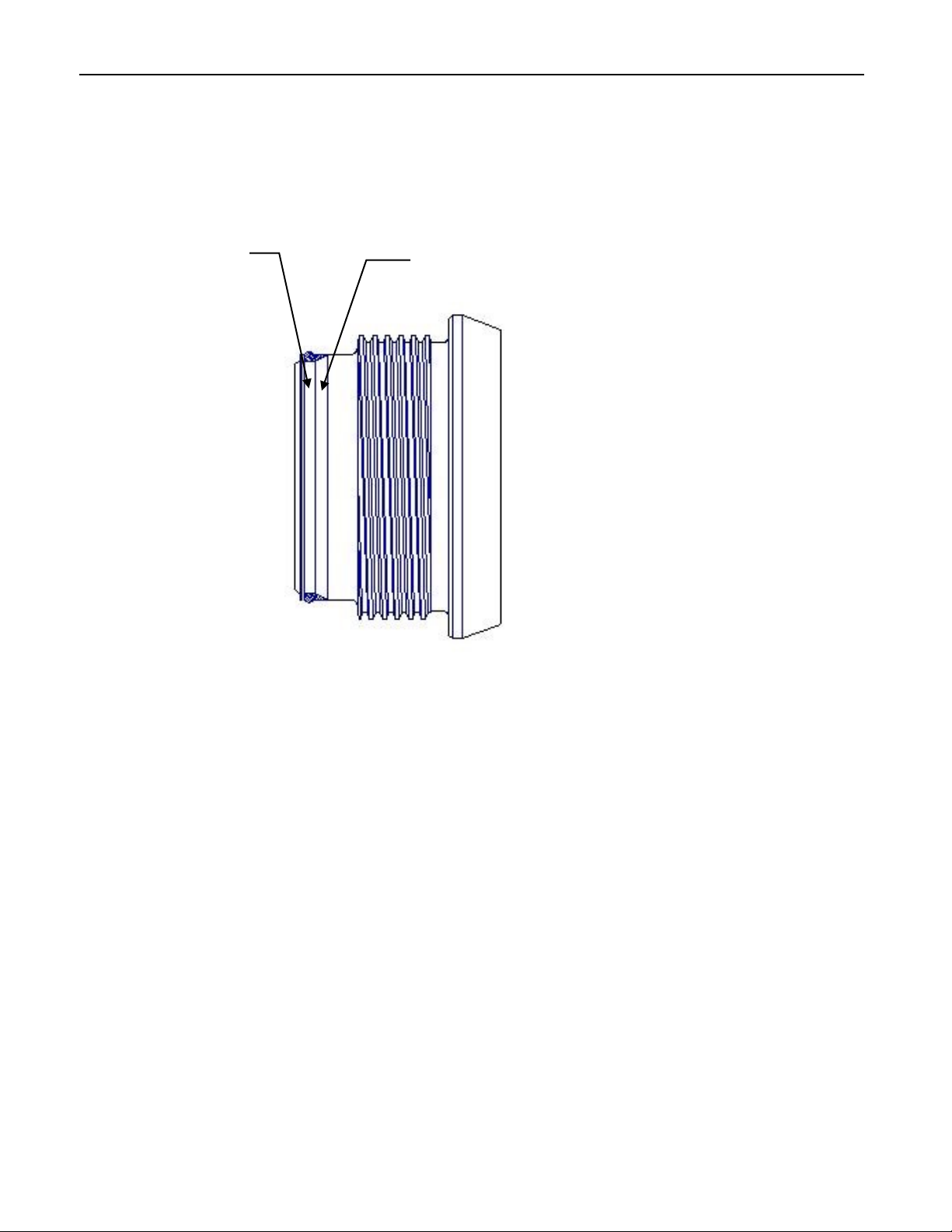
About the High Pressure Seal ..............................................................................................................P-2
Where to Find Help..............................................................................................................................P-3
Section 1 - Installation.....................................................................1-1
Site Requirements ................................................................................................................................ 1-1
Connecting Air and Water ................................................................................................................... 1-1
Connecting Power to the Curing Chamber .......................................................................................... 1-2
Section 2 - Curing Chamber Controls..............................................2-1
Safety Procedures................................................................................................................................. 2-1
Power Switch ................................................................................................................................... 2-1
Model 7050 Temperature Controller ............................................................................................... 2-1
Drain Cylinder/Fill Cylinder switch ................................................................................................ 2-2
Heater Switch................................................................................................................................... 2-2
Pressurize Cylinder Switch.............................................................................................................. 2-2
Cool Cylinder Switch....................................................................................................................... 2-2
Cylinder Drain Valve....................................................................................................................... 2-2
Pump Pressure Adjust Regulator ..................................................................................................... 2-3
Temperature Limit Alarm ................................................................................................................ 2-3
Temperature Limit Alarm Reset ...................................................................................................... 2-3
Section 3 - Operation.......................................................................3-1
Preparation of Cement Sample ............................................................................................................ 3-1
Installing Cylinder Plug ....................................................................................................................... 3-1
Filling Cylinder with Water................................................................................................................. 3-1
Temperature Control............................................................................................................................ 3-2
Pressure Control................................................................................................................................... 3-2
Running the Test.................................................................................................................................. 3-3
If Temperature Limit Alarm Occurs ................................................................................................ 3-3
Cooling the Cylinder............................................................................................................................ 3-3
Draining the Cylinder .......................................................................................................................... 3-4

T-ii TABLE OF CONTENTS
Section 4 - Maintenance and Servicing ...........................................4-1
Maintenance......................................................................................................................................... 4-1
Troubleshooting ................................................................................................................................... 4-1
Section 5 –Replacement Parts ........................................................5-1
Section 6 - Drawings and Schematics..............................................6-1

PREFACE P-1
General Information
Initial Inspection
The Model 7360V Vertical Curing Chamber was tested and inspected before the unit was
shipped from Chandler Engineering. The curing chamber was run through a typical
temperature and pressure profile prior to shipment. Carefully uncrate and inspect the curing
chamber and any accessories. If the unit is received in a damaged condition, immediately
notify Chandler Engineering in writing, and immediately file a claim with the carrier.
Features
The Model 7360V Vertical Curing Chamber is equipped with the following features:
Ramp and soak PID temperature controller.
Variable high pressure limit control. High-pressure limit may be adjusted using high-
pressure limit regulator located on the front panel.
The instrument is equipped with a pump pressure adjustment, which can be used to maintain
the pressure in the instrument above a desired lower limit. If the instrument pressure drops
below the lower limit, the pump will increase the pressure back up above the lower limit.
High temperature alarm
If the cylinder temperature exceeds the limit, the high temperature alarm will cause the heater
to shut off. This is indicated by a lighted pushbutton-switch on the front panel. The high
temperature alarm must be reset manually using the front panel reset switch before the heater
will again become operational.
Specifications
Temperature Control: External 3000-Watt heater and internal thermocouple connected to
Temperature Controller. This controller is capable of ramp and soak or multi-set-point PID
control.
Pressurizing System: The unit is pressurized using an air driven hydraulic pump with water
used as the pressurizing medium. The pressure can be accurately controlled using the HIGH
PRESSURE LIMIT REGULATOR and the PUMP PRESSURE ADJUST REGULATOR.
Maximum Operating Pressure: 6000 psi/41.4 MPa
Maximum Operating Temperature: 600°F/315°C
Heater

P-2 PREFACE
Heater power: 3000 Watts
Heater type: External, 2 piece, mica band-heater
Heater control: Solid-state relay with temperature feedback
Power Requirements
Input voltage: 220 ± 10% VAC, single phase
Input power: 3.2 kVA
Input frequency: 50 or 60 Hz
Mechanical
Height: 20 in/51 cm
Width: 21.5 in/55 cm
Length: 19 in/48 cm
Weight: 150 lb/68 kg
Pressure vessel material: AISI/SAE 15-5 PH stainless steel
Environmental
Operating temperature: 32°F - 105°F/0°C - 40°C
Operating humidity: 0 - 95% non-condensing
Air and water supply
Compressed air: 75-125 psig/517 - 862 kPa
Water: 20 - 40 psig/135 - 275 kPa
Fittings: 1/4 in/6.4 mm
About the High Pressure Seal
The cylinder and plug used in the Model 7360V Vertical Curing Chamber were designed for
reliable sealing and ease of use. The principle behind the seal design is outlined below. You
may find it convenient to refer to Figure 1 for further clarification.
The primary high-pressure sealing element is the metal seal ring (2). As the pressure inside
the cylinder increases, the seal ring is wedged between the plug (1) and the cylinder forming
a tight metal-to-metal seal. One feature of this seal is that as pressure increases, the seal
becomes tighter.
At low pressures, however, the metal seal ring will not make an effective seal. For this
reason, an internal O-ring (3) is added below the metal seal ring (2). The internal O-ring is
used to make the initial seal. When the pressure inside the cylinder is increased, the internal
O-ring (3) is forced against the metal seal ring (2), which wedges between the plug and
cylinder and creates the metal-to-metal seal. The retaining ring (4) is simply used to secure
the metal seal ring and the internal O-ring in place.
During high temperature tests (exceeding 500°F/260°C) the internal O-ring may be damaged
to the extent that it can no longer form an effective seal. This will not affect the metal-to-
metal seal in any way as long as the pressure in the cylinder is maintained above 1600 psi/11
MPa.

PREFACE P-3
NOTE: Do not attempt to operate the instrument without the metal seal ring (2) and
the internal O-ring (3). Doing so could cause seal failure and the release of
hot water or steam.
Where to Find Help
In the event of problems, the local sales representatives will be able to help or the personnel
at Chandler Engineering can be contacted.
•Telephone: 918-250-7200
•FAX: 918-459-0165
•E-mail: [email protected]
•Website: www.chandlereng.com
Metal Seal
Elastomer O-ring


SECTION 1 - INSTALLATION 1-1
Section 1 - Installation
Site Requirements
This instrument has been designed with operator safety as a primary consideration. The
following safety procedures are recommended to help ensure safety for both operator and
other laboratory personnel.
•Locate the instrument in a low traffic area.
•Post signs where the instrument is being operated to warn other personnel.
•A fire extinguisher, Type 8 BC, should be located within 50 feet/15 meters of the
instrument.
•Have the safety officer at your plant or laboratory review the safety aspects of the
instrument and installation and approve the operational and installation procedures.
Connecting Air and Water
This instrument requires compressed air at pressures between 75 and 125 psi/517 - 862 kPa.
Water is also required at pressures between 20 and 40 psi/135 - 275 kPa. All air, water, and
steam fittings have ¼-inch NPT threads.
•Connect air supply line to the fitting on the rear of the instrument marked AIR INLET.
•Connect the water supply line to the fitting on the rear of the instrument marked WATER
INLET.
•Connect water drain line to the fitting on the rear of the instrument marked COOLING
WATER OUTLET. Copper drain line is strongly recommended as the hot water may
melt rubber or plastic drain lines.
•Connect the cylinder drain line to the fitting on the rear of the instrument marked
CYLINDER WATER DRAIN. Only metal (copper or stainless steel) drain line should
be used as the steam and hot water released will melt rubber or plastic drain lines.
Caution: Connecting the COOLING WATER OUTLET and CYLINDER WATER
DRAIN lines is not recommended. If these two lines are connected, water
may back up into the cylinder if the plug is removed while the CYLINDER
DRAIN valve is open.

1-2 INSTALLATION
Connecting Power to the Curing Chamber
This instrument operates on 220 ± 10% VAC, 50 or 60 Hz, single phase, 15A electrical
current. The instrument is equipped with a power cord and should be connected to an
appropriately rated power source. (The earth ground connection on the rear of the instrument
should be connected to a metal water pipe, a metal rod driven in the ground, or other
appropriate earth ground.)
Note: Remove ALL power connections from the unit before opening the covers or
performing any service operations. The High Current 220 VAC or 120 VAC
voltages inside the unit can KILL

SECTION 2 –CURING CHAMBER CONTROLS 2-1
Section 2 - Curing Chamber Controls
Safety Procedures
The following safety procedures are recommended to help ensure operator safety:
•Read and understand the instructions before operating the instrument.
•Never exceed the temperature or pressure ratings listed on the front panel.
•Disconnect main power before servicing the instrument.
•Turn off heater at the completion of the test.
•Do not attempt to open the CYLINDER DRAIN valve until the water temperature is
below 200°F (93°C).
•Use caution when opening the CYLINDER DRAIN valve at high temperatures and
pressures.
•Make certain that the side panels are in place when operating the instrument.
•Always install a new plug O-ring if the cylinder temperature has exceeded 350°F/177°C.
Control Panel Functions
Figure 2 shows how the front control panel is designed. You may find it convenient to refer
to this figure as you study the control panel functions.
Power Switch
The Power switch controls all electrical power to the instrument.
Temperature Controller
The Temperature Controller controls the 3000-Watt cylinder heater. The water temperature
is measured using a thermocouple inserted through the bottom of the cylinder. The controller
may be programmed in a variety of ways to provide different test conditions.
For the heater to function, the HEATER switch must be in the ON position and the
temperature controller must be operating. If a heat-up cycle must be stopped, the heater can
be turned OFF by switching the HEATER switch to the OFF position or by pressing the F1
(Auto / Manual) button on the controller.

2-2 CURING CHAMBER CONTROLS
Please refer to the 9050,9051,9060,9061,9080,9081 Controller manual for detailed
instructions on the operation of the temperature controller.
Drain Cylinder/Fill Cylinder switch
The DRAIN CYLINDER/FILL CYLINDER switch is used to fill the cylinder with water or
to remove water from the cylinder. When the switch is in the FILL CYLINDER position, the
cylinder will fill with water. The switch must be in the FILL CYLINDER position or the
pump will not operate. In general, anytime the instrument is in use, the switch should be in
the FILL CYLINDER position. At the conclusion of a test, the CYLINDER DRAIN valve
should be opened and the switch moved to the DRAIN CYLINDER position. This will
remove all water from the cylinder. When the unit is not in use, the switch should be in the
OFF position.
Heater switch
The HEATER switch controls all of the power to the heater elements. This switch will
override any control to the heater by the Temperature Controller.
Pressurize Cylinder switch
The PRESSURIZE CYLINDER switch is used to increase the pressure in the cylinder by
turning the hydraulic pump ON.
Cool Cylinder switch
The COOL CYLINDER switch controls the flow of water to the internal cooling coils. This
switch should always be in the OFF position during a test and then switched to the ON
position at the completion of the test to cool the cylinder.
Cylinder Drain valve
The CYLINDER DRAIN valve is used in conjunction with the DRAIN CYLINDER switch
to drain water from the cylinder after completion of a test. The CYLINDER DRAIN valve
should never be opened until all the pressure has been bled from the cylinder and the
temperature is below 200°F/93°C.
High Pressure Limit Regulator
The HIGH PRESSURE LIMIT REGULATOR knob is used to select the upper set point
pressure prior to the beginning of the test. To select the desired pressure upper limit, turn the
HIGH PRESSURE LIMIT REGULATOR knob in (clockwise) as far as it will go. With the
cylinder filled with water and the FILL CYLINDER switch in the ON position, turn the
pump switch to the ON position until the desired pressure set point is reached. The PUMP
PRESSURE ADJUST regulator may need to be adjusted if the pump will not reach the
desired pressure. Slowly turn the HIGH PRESSURE LIMIT REGULATOR knob out
(counterclockwise) until the pressure just begins to drop. The high-pressure limit regulator is
now at the proper set point. The high-pressure limit regulator will only keep the pressure

SECTION 2 –CURING CHAMBER CONTROLS 2-3
from exceeding the set point. Maintaining the pressure above a certain level can be done by
adjusting the PUMP PRESSURE ADJUST regulator.
Pump Pressure Adjust Regulator
The PUMP PRESSURE ADJUST regulator is used to control the maximum pressure of the
hydraulic pump. Turning the regulator knob in (clockwise) will increase the maximum pump
pressure. Turning the regulator knob out (counterclockwise) will decrease the maximum
pump pressure. When the PRESSURIZE CYLINDER switch is in the ON position, the
PUMP PRESSURIZE ADJUST regulator may be used to maintain cylinder pressure above a
certain level. The PUMP PRESSURE ADJUST may also be used to slowly and quietly
increase the cylinder pressure. This is done by turning the PUMP PRESSURE ADJUST
knob clockwise while the PRESSURIZE CYLINDER switch is in the ON position.
Temperature Limit Alarm
The TEMPERATURE LIMIT ALARM switch light will come on if the maximum allowable
cylinder temperature is exceeded. When a TEMPERATURE LIMIT ALARM occurs, the
heaters are automatically switched off. The TEMPERATURE LIMIT ALARM switch will
not go off and the heaters will not operate until the manual TEMPERATURE LIMIT
ALARM switch is pressed.
Temperature Limit Alarm Reset
The Temperature Limit Alarm Reset is used to reset the TEMPERATURE LIMIT ALARM.
When the alarm is tripped, the light will not go off and the heaters will not operate until the
TEMPERATURE LIMIT ALARM switch is pressed.


SECTION 3 –OPERATION 3-1
Section 3 - Operation
Preparation of Cement Sample
Assemble two side plates, one bottom plate, two end plates, and three partitions of the mold
assembly. Do not over-tighten nuts.
Fill the greased molds with cement slurry prepared in accordance with API Specification 10,
Specification for Materials and Testing for Well Cements.
The slurry should be puddled and excess slurry removed from the mold.
Attach the top plate with the slotted side down. Place the molds in the cylinder.
Installing Cylinder Plug
Before the plug is installed into the cylinder, make certain that the plug threads, O-rings, and
metal sealing surfaces have been thoroughly lubricated with Moly grease or similar high
temperature lubricant.
Note: Install a new O-ring after any test in which the temperature exceeds
350°F/177°C.
Check internal O-ring on bottom of plug. Replace if it becomes cut, torn, or brittle.
Screw plug into cylinder. Do not tighten plug more than hand tight. Over tightening the
plug will not cause more effective sealing and may cause difficulty in removing the plug
from the cylinder. See ABOUT THE HIGH PRESSURE SEAL in the Preface.
Filling Cylinder with Water
Loosen the small plug on the top of the cylinder to allow air to escape while filling. Make
sure that all valves are closed and all switches (except power switch) are in the off position.
Place FILL CYLINDER switch in the ON position.
When water escapes from the small plug, indicating the cylinder is full, tighten with a 5/8”
wrench.

3-2 SECTION 3 - OPERATION
Temperature Control
Complete instructions on the programming and operation of the Temperature Controller can
be found in the 9050,9051,9060,9061,9080,9081 Controller manual.
Pressure Control
1. Turn the HIGH PRESSURE LIMIT REGULATOR knob all the way in (clockwise).
2. Turn the PRESSURIZE PUMP switch to the ON position until the desired set point
pressure is reached. Increase the pump pressure by turning the PUMP PRESSURE
ADJUST regulator clockwise, if necessary, to reach the desired pressure. If the cylinder
does not begin to pressurize after a few seconds, it may indicate trapped air in the
cylinder. The trapped air can be removed by loosening the 5/8” hex plug in the top of the
cylinder.
3. Turn the HIGH PRESSURE LIMIT REGULATOR knob out (counterclockwise) until the
pressure begins to drop. The upper limit on pressure has now been set. The pressure will
automatically bleed off when this set point pressure is reached.
4. Open the CYLINDER DRAIN valve to bleed the pressure.
5. Close the CYLINDER DRAIN valve.
6. Turn the PUMP PRESSURE ADJUST regulator out (counterclockwise) as far as it will
go.
7. Turn the PRESSUIZE CYLINDER switch to the ON position.
Caution: Do not set the instrument at a pressure that will allow the water to turn to
steam. A pressure of 1600 psi/11 MPa at a temperature of 600°F/315°C is
adequate to prevent this.
8. Open the CYLINDER DRAIN valve to bleed the pressure, if desired.
9. Close the CLINDER DRAIN valve.

SECTION 3 –OPERATION 3-3
Running the Test
If necessary, press the RESET button to reset the TEMPERATURE LIMIT ALARM.
Make certain the FILL CYLINDER switch is in the ON position; the HEATER switch is in
the ON position; and the COOL CYLINDER switch is in the OFF position.
Also make certain the CYLINDER DRAIN valve is closed and the cylinder is filled with
water.
Program and start the Temperature Controller.
Use the PRESSURIZE CYINDER switch to increase the cylinder pressure to the desired
level, if necessary. The PRESSURIZE CYLINDER switch may be left in the ON position to
maintain a minimum pressure if the PUMP PRESSURE ADJUST regulator has been set as
outlined in the Pressure Control section.
If Temperature Limit Alarm Occurs
If the cylinder exceeds its maximum operating temperature, a TEMPERATURE LIMIT
ALARM will occur. When this alarm occurs, the yellow pushbutton switch will light and the
heaters will cease to operate. The only way to reset this alarm is by pressing the lighted
switch on the front panel. If a TEMPERATURE LIMIT ALARM occurs, the instrument
should not be operated again until the reason for the alarm is found and corrected.
Cooling the Cylinder
The 7360V Vertical Curing Chamber is equipped with internal cooling coils for rapid
cylinder cooling at the completion of a test. The following is the procedure for cylinder
cooling.
1. Make certain that the PUMP PRESSURE ADJUST regulator has been set so that
pressure in the cylinder is maintained at 1600 psi/11 MPa or greater until the temperature
of the cylinder is below 200°F/93°C. This will prevent water in the cylinder from
flashing into steam.
2. Turn the PRESSURIZE CYLINDER switch to the ON position if it is not already in the
ON position.
3. Turn the HEATER switch to the OFF position.
4. Turn the COOL CYLINDER switch to the ON position.
5. Press the F1 button (Automatic / Manual Mode) on the Temperature Controller.

3-4 SECTION 3 - OPERATION
6. When the cylinder has cooled below 200°F/93°C the PRESSURIZE CYLINDER switch
may be turned to the OFF position and the CYLINDER DRAIN valve may be opened
which will allow water to circulate through the cylinder for more rapid cooling.
7. Cool the cylinder as long as API Specification 10 permits. If cooling water circulation is
stopped prematurely, heat from the cylinder may cause the temperature of the water in
the cylinder to rise and flash the water to steam.
Draining the Cylinder
1. Turn all valves to the OFF position.
2. Turn the PRESSURIZE CYLINDER and FILL CYLINDER switches to the OFF
position.
3. Open the CYLINDER DRAIN valve.
4. Turn the DRAIN CYLINDER switch to the ON position until the water has drained from
the cylinder. A minimum of two minutes is recommended.
5. Close the CYLINDER DRAIN valve.
6. Turn the FILL CYLINDER/DRAIN CYLINDER switch to the OFF position.
7. When all the pressure has been removed from the cylinder, carefully remove the plug
from the cylinder.
Note: Cylinder plug may be hot. The plug weighs 22 pounds/10 kg. Use caution to
prevent dropping the plug.
The molds may now be removed from the cylinder.

SECTION 4 –MAINTENANCE AND SERVICING 4-1
Section 4 - Maintenance and Servicing
The 7360V Curing Chamber was designed to require little maintenance and servicing. The
following guidelines are recommended to help insure years of trouble free service. In the
event a problem occurs, a troubleshooting guide is listed following the maintenance
guidelines.
Maintenance
Make certain that the plug and cylinder threads are clean and well lubricated with Moly
grease or other high temperature lubricant.
Check the internal plug O-ring periodically for cuts, tears, or deterioration. Replace if any of
these are evident.
Note: You must install a new O-ring after any test in which the temperature exceeds
350°F/177°C.
Clean all cement out of the bottom of the cylinder.
Troubleshooting
The table on the following page is intended to help identify the source of any malfunctions
that may occur with the 7360V Vertical Curing Chamber.

4-2 MAINTENANCE AND SERVICING
TROUBLESHOOTING
Symptom
Possible Cause
Remedy
Heater will not operate
Instrument not receiving
power
Pressure will not bleed
Instrument will not hold
pressure
Blown rupture disk
Controller does not
maintain adequate
temperature profile
Cylinder cannot be
pressurized to desired
level
Temperature Limit
Alarm
Open circuit in heater
wiring
Instrument not plugged in
Blown fuse on rear panel
Blown fuse in external
wiring
Drain line blocked with
cement
Leak in cylinder or tubing
Damaged valve or
pressure regulator seat
Pressure regulator is
blocked with cement
Wrong tuning parameters
Malfunctioning controller
High Pressure Limit
regulator set wrong
Insufficient air pressure to
pump
Find cause and correct,
press reset
Find and eliminate open
circuit
Plug into appropriate
outlet
Replace fuse
Replace fuse
Locate blockage and
remove
Visually check for leaks
in cylinder and stainless
steel tubing and repair
Isolate problem and
repair or replace
Clean pressure regulator
Check tuning parameters
Repair or replace
controller
Adjust regulator
Check air supply and
pump pressure adjust
regulator.
Table of contents
Other Ametek Industrial Equipment manuals

Ametek
Ametek Dunkermotoren BGE 5510 dPro IO/CO User manual

Ametek
Ametek Ripple NX600-1000-5 User manual

Ametek
Ametek TESEQ KEMA 801A User manual

Ametek
Ametek dunkermotoren BG dCore Series Instruction Manual

Ametek
Ametek Universal Analyzers 3000 Series User manual

Ametek
Ametek Gemco 1995A Series Assembly instructions

Ametek
Ametek Chandler Engineering 3065 User manual

Ametek
Ametek ASCEND Series User manual

Ametek
Ametek VersaSCAN User guide

Ametek
Ametek ORTEC MOBIUS-B User manual