Ametek Magnetrol E4 Modulevel User guide
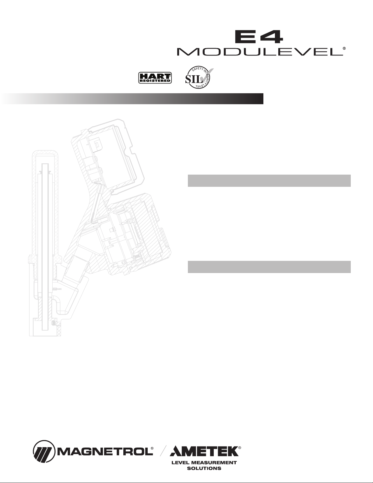
Liquid Level
Displacer Transmitter
SIL Safety Manual for
E4 Modulevel
This manual complements and is intended to be used with
the E4 Modulevel®Installation and Operating manual
(Bulletin 48- 3 ).
Application
The E4 Modulevel®Liquid Level Displacer Transmitter
can be applied in most process or storage vessels, bridles,
bypass chambers, interfaces, sumps, and pits up to the
unit pressure and temperature ratings. The E4
Modulevel can be used in liquids, clean or dirty, light
hydrocarbons to heavy acids (SG=0.23 to 2.20) to meet
the safety system requirements of IEC 6150 .
Benefits
The E4 Modulevel provides the following benefits to
your operation:
• Suitable for use to SIL 2 as standalone device inde-
pendently assessed (hardware assessment) by exida as
per IEC 6150 / IEC 61511.
• Capable of outputting total level, interface level, or
specific gravity.
• Range Spring/LVDT design yields performance bene-
fits over traditional torque tube displacer transmitters.
• Full range of hazardous location approvals with inter-
national certificates.
Functional Safety Manual

48-652 E4 Modulevel Displacer Level Transmitter - SIL
Table of Contents
1.0 Introduct on ...................................................................3
1.1 Product Description..................................................3
1.2 Theory of Operation.................................................3
1.3 Determining Safety Integrity Level (SIL) ..................4
2.0 Level Measur ng System .................................................4
2.1 Applicable Models.....................................................4
2.2 Miscellaneous Electrical Considerations ....................5
2.2.1 Pollution Degree 2 .........................................5
2.2.2 Overvoltage ....................................................5
3.0 Mean T me To Repa r (MTTR).....................................5
4.0 Supplementary Documentat on......................................5
5.0 Instruct ons ....................................................................6
5.1 Systematic Limitations ..............................................6
5.1.1 Application.....................................................6
5.1.2 Environmental................................................6
5.2 Skill Level of Personnel .............................................6
5.3 Necessary Tools .........................................................6
5.4 Storage ......................................................................7
5.5 Installation ................................................................7
5.6 Configuration ...........................................................7
5.6.1 General...........................................................7
5.6.2 Write Protecting / Locking.............................7
5.7 Site Acceptance Testing .............................................7
5. Recording results.......................................................7
5.9 Maintenance .............................................................
5.9.1 Diagnostics.....................................................
5.9.2 Troubleshooting .............................................
6.0 Recurrent Funct on Tests ...............................................8
6.1 Proof Testing .............................................................
6.1.1 Introduction...................................................
6.1.2 Interval...........................................................
6.1.3 Recording Results...........................................9
6.1.4 Proof Test Procedure.......................................9
7.0 Append ces ...................................................................10
7.1 FMEDA Report Management Summary ................10
7.2 Specific Model E4 values.........................................11
7.3 PFD graph ..............................................................11
7.4 Report- Lifetime of Critical components.................11
E4 Modulevel®D splacer Level Transm tter
SIL Safety Manual

3
48-652 E4 Modulevel Displacer Level Transmitter - SIL
1.0 Introduction
1.1 Product Description
The E4 Modulevel is a loop-powered, two-wire, 24 VDC
level transmitter that uses simple buoyancy principles in
combination with a precision range spring and a highly
accurate LVDT (linear variable differential transformer) to
detect and convert liquid level changes into a
stable 4–20 mA output signal. The electronics are housed in
an ergonomic, dual-compartment enclosure that is angled
for ease of wiring and calibration.
The E4 Modulevel has microprocessor-based electronics
with HART compatible output, in addition to the standard
4–20 mA output. The E4 Modulevel supports the
FDT/DTM standard and a PACTware™PC software
package allows for additional configuration and trending
capabilities.
The linkage between the level sensing element and output
electronics provides a simple mechanical design and con-
struction. The vertical in-line design of the transmitter
results in low instrument weight and simplified installation.
The instrument comes in a variety of configurations and
pressure ratings for varied applications.
1.2 Theory of Operation
The E4 Modulevel Displacer Level Transmitter relies on the
principles of buoyancy to convert mechanical movement to
an electronic output.
The movement of the range spring, as it compresses or elon-
gates based on the volume of displacer submerged in the
liquid, causes movement of a special LVDT core attached to
the spring. The LVDT technology converts the movement
of the LVDT core within the LVDT to a stable 4–20 mA
output signal. The position of the core, with respect to a
primary and two secondary windings, induces voltage in
each winding. The comparison of the induced voltages
within the microprocessor of the E4 Modulevel results in
very accurate level or interface level output.
The E4 Modulevel can, alternatively, be set up to track the
changing density of a liquid over a known density range and
convert that into a stable 4–20 mA output signal. As the
density of the liquid changes, so does the mass of the liquid
displaced by the displacer. This resulting change in buoyancy
force on the displacer causes movement of the LVDT core
needed to convert the density change to the 4–20 mA signal.

448-652 E4 Modulevel Displacer Level Transmitter - SIL
1.3 Deter ining Safety Integrity Level (SIL)
Tables 1 and 2 define the criteria for the achievable SIL
against the target mode of operation in Demand Mode
Operation.
Table 1 shows the relationship between the SIL and the
Probability of Failure on Demand Average (PFDavg).
Table 2 can be used to determine the achievable SIL as a
function of the Hardware Fault Tolerance (HFT) of which
the level transmitter is one component (Type B - complex
components as per IEC 6150 -2).
Failure rate data used for the E4 analysis meet the exida cri-
teria for Route 2H; therefore, the E4 meets the hardware
architectural constraints for up to SIL 2 @ HFT=0 (or SIL
3 @ HFT=1) when the listed failure rates are used.
2.0 Level Measuring Syste
Figure 1 shows the structure of a typical measuring system
incorporating the E4 Modulevel.
This SIL rated device is available only with an analog signal
with HART communications. The measurement signal used
by the logic solver must be the analog 4-20 mA signal pro-
portional to the level generated.
For fault monitoring, the logic unit must recognize both
high alarms (≥ 21.5 mA) and low alarms (≤ 3.6 mA). If the
logic solver loop uses intrinsic safety barriers, caution must
be taken to ensure the loop continues to operate properly
under the low alarm condition.
The only unsafe mode is when the unit is reading an incor-
rect level within the 4-20 mA range (> ±2% deviation).
Magnetrol defines a safe failure as one in which the 4-20
mA current is driven out of range (i.e., less than 3. mA or
greater than 20.5 mA).
Fault selection of the E4 Modulevel is 3.6 mA, 22.0 mA, or
HOLD, and is selected by the user. HOLD should never be
chosen as the Fault output in a safety application.
2.1 Applicable Models
This manual is applicable to the following models of the
E4 Modulevel Liquid Level Displacer Transmitter:
E4M-51xx-xxx-xx-xxx
Figure 1
Typical System
Table 2
Minimum hardware fault tolerance
Type B sensors, final elements and non-PE logic solvers
Hardware Fault Tolerance (HFT)
012
Not
Allowed SIL 1 SIL 2
SIL 1 SIL 2 SIL 3
SIL 2 SIL 3
SIL 3
Table 1
SIL vs. PFD avg
Safety
Integrity Level
(SIL)
Target Average
probability of failure
on demand (PFDavg)
4≥10-5 to <10-4
3≥10-4 to <10-3
2≥10-3 to <10-2
1≥10-2 to <10-1

5
48-652 E4 Modulevel Displacer Level Transmitter - SIL
2.2 Miscellaneous Electrical Considerations
2.2.1 Pollution Degree 2
The E4 Modulevel Level Displacer Transmitter is designed
for use in Category II, Pollution Degree 2
installations.
A nonconductive pollution of the sort where occasionally a
temporary conductivity caused by condensation must be
expected. This is the usual pollution degree used for
equipment being evaluated to IEC/EN 61010.
2.2.2 Overvoltage
The E4 Modulevel has overvoltage protection per CE
requirements; this protection is to 1000 volts when consid-
ering Hi-pot, Fast Transients, and Surge. Therefore, there
should be no unsafe failure modes up to 1 KV.
Overvoltage Category II is a local level, covering appliances,
portable equipment, etc., with smaller transient overvoltages
than those characteristic of Overvoltage Category III. This
category applies from the wall plug to the power supply iso-
lation barrier (transformer). The typical plant environment
is Overvoltage Category II, so most equipment evaluated to
the requirements of IEC/EN 61010 are considered to
belong in that classification.
3.0 Mean Ti e To Repair (MTTR)
SIL determinations are based on a number of factors including
the Mean Time To Repair (MTTR). This variable, along
with a number of other variables, are an attribute of end
user practices.
4.0 Supple entary Docu entation
The E4 Modulevel Installation and Operating Manual
(Bulletin 4 -636) must be available for installation of the
measuring system.
The following Electronic Device Description File is required
if HART is used:
E4 M dulevel HART Revisi n Table
HART Versi n HCF Release Date C mpatible with S ftware
Dev Rev 1, 2023 Version 1.0a and later
DD Rev 1
For device installations in a classified area, the relevant
safety instructions and electrical codes must be followed.

5.0 Instructions
5.1 Syste atic Li itations
The following application and environmental limitations
must be observed to avoid systematic failures.
5.1.1 Application
The E4 Modulevel transmitter should be located for easy
access for service, configuration, and monitoring. There should
be sufficient headroom to allow installation and removal of the
transmitter head, and, in cases of tank top configuration, the
displacer. Special precautions should be made to prevent expo-
sure to corrosive atmosphere, excessive vibration, shock, or
physical damage. The E4 Modulevel should only be used for
applications in which buildup of solid materials on the spring
or in the enclosing tube is not an issue.
The operating temperature range for the transmitter electronics
is -40 to + 0 °C (-40 to +176 °F). The operating temperature
range for the digital display is -20 to +70 °C (-5 to +160 °F).
Caution: Operation of all buoyancy type level devices should be
done in such a way as to minimize the action of dynamic
forces on the float or displacer sensing element. Good
practice for reducing the li elihood of damage to the con-
trol is to equalize pressure across the device very slowly.
5.1.2 Environmental
See E4 Modulevel Installation and Operating Manual
(Bulletin 4 -636) for environmental limitations.
5.2 Skill Level of Personnel
Personnel following the procedures of this safety manual
should have technical expertise equal to or greater than that
of a qualified instrument technician.
5.3 Necessary Tools
No special equipment or tools are required to install
E4 Modulevel. The following items are recommended:
• Wrenches, flange gaskets, and flange bolt ng
appropr ate for process connect on(s)
• Flat-blade screwdr ver
• Level
• 1⁄8" Allen wrench
• 24 VDC power supply, 23 mA m n mum
• D g tal mult meter
• 250 to 450 ohm res stor for HART commun cat on
648-652 E4 Modulevel Displacer Level Transmitter - SIL

5.4 Storage
The E4 Modulevel should be stored in its original shipping
box and not be subjected to temperatures outside the stor-
age temperature range -40 to + 5 °C (-50 to +1 5 °F), as
shown in the E4 Modulevel Installation and Operating
Manual (Bulletin 4 -636).
5.5 Installation
Refer to the E4 Modulevel Displacer Level Transmitter
Installation and Operating Manual (Bulletin 4 -636) for
the proper installation instructions.
This SIL evaluation has assumed that the customer will be
able to acknowledge an over or under current condition via
the logic solver.
5.6 Configuration
5.6.1 General
The E4 Modulevel can be configured via the local display,
the HART compatible handheld communicator, or a laptop
computer with PACTware.
5.6.2 Write Protecting / Locking
The E4 Modulevel transmitter is password protected. Refer
to the Installation and Operating Manual (Bulletin 4 -636)
for information on password protection.
5.7 Site Acceptance Testing
Complete a site acceptance test to ensure proper operation
after installation and configuration. This procedure is iden-
tical to the Proof Test Procedure described in Section 6.1.4
of this document.
5.8 Recording Results
Results of Site Acceptance Testing must be recorded for
future reference.
7
48-652 E4 Modulevel Displacer Level Transmitter - SIL
5.9 Maintenance
The only maintenance required is the proof test.
• Report all failures to the factory.
• Firmware can only be upgraded by factory personnel.
5.9.1 Diagnostics
Internal diagnostic testing does a complete cycle about 16
times per second (every 60 ms). A message will appear and
the output current will be driven to 3.6 or 22 mA (cus-
tomer dependent) upon detection of a fault. Never specify
HOLD as the fault signal in a safety application.
5.9.2 Troubleshooting
Refer to E4 Modulevel Installation and Operating Manual
(Bulletin 4 -636) for troubleshooting device errors.
6.0 Recurrent Function Tests
6.1 Proof Testing
6.1.1 Introduction
Following are the procedures used to detect Dangerous
Undetected (DU) failures. The proof test coverage for the
various product configurations is provided in the table
below.
6.1.2 Interval
To maintain the safety integrity level of a safety instrumented
system, it is imperative that the entire system be tested at regu-
lar time intervals (TI in the appropriate standards). The SIL for
the E4 Modulevel is based on the assumption that the end user
will carry out these tests and inspection at least once per year.
The onus is on the owner/operator to select the type of inspec-
tion and the time period for these tests.
The system check must be carried out to prove that the safety
functions meet the IEC specification and result in the desired
response of the safety system as a whole.
Device λDUPT
(FIT)
Pr f Test
C verage
E4 Local 14 76%
E4 Remote 14 77%
848-652 E4 Modulevel Displacer Level Transmitter - SIL

6.1.3 Recording results
Record the results of the Proof Test for future reference.
6.1.4 Proof Test Procedure
A suggested proof test is described below.
1. Bypass the safety function and take appropriate action to
avoid a false trip.
2. Use HART communications to retrieve any diagnostics and
take appropriate action.
3. Send a HART command to the transmitter to go to the
high alarm current output and verify that the analog current
reaches that value. ¿
4. Send a HART command to the transmitter to go to the low
alarm current output and verify that the analog current
reaches that value. ➁
5. Inspect the transmitter for any leaks, visible damage or con-
tamination.
6. Perform a two-point calibration ➂of the transmitter over
the full working range.
7. Remove the bybass and otherwise restore normal operation.
¿This tests for compliance voltage problems such as a low loop power
supply voltage or increased wiring resistance. This also tests for other
possible failures.
➁This tests for possible quiescent current related failures.
➂If the two-point calibration is performed with electrical instrumentation,
this proof test will not detect any failures of the sensor.
9
48-652 E4 Modulevel Displacer Level Transmitter - SIL
10 48-652 E4 Modulevel Displacer Level Transmitter - SIL
7.0 Appendices
7.1 FMEDA Report: Exida Manage ent Su ary
Table of contents
Other Ametek Transmitter manuals


Popular Transmitter manuals by other brands


Dejero
Dejero EnGo 3x manual

Rosemount
Rosemount 4600 Reference manual

Speaka Professional
Speaka Professional 2342740 operating instructions

trubomat
trubomat GAB 1000 instruction manual

Teledyne Analytical Instruments
Teledyne Analytical Instruments LXT-380 instructions

Rondish
Rondish UT-11 quick start guide


