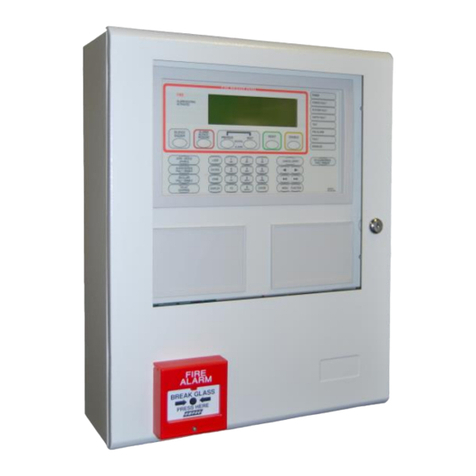
Ampac EV3000 4210-0030 Product guide

Occupant Warning &
Intercommunications System
Commissioning Log Book
MAN1528-9
EV3000

Table Of Contents Page No
1Damage Report Form................................................................................... 1
2Purpose......................................................................................................... 2
2.1 Scope...................................................................................................................2
2.2 References...........................................................................................................2
2.2.1 EV3000 System Manuals:.....................................................................2
2.2.2 Australian Standards............................................................................2
2.3 System Overview.................................................................................................2
3Wiring............................................................................................................ 3
3.1 Mains Connection ...............................................................................................3
3.2Speaker Connection............................................................................................3
3.3 Warden Intercom Point Connection ...................................................................3
3.4 Warden Intercom Point with EAID connected....................................................3
3.5 Visual Alarm Connected .....................................................................................3
3.6 Fire Alarm Inputs.................................................................................................3
4Commissioning Record............................................................................... 5
5Completing the Commissioning Report..................................................... 6
6Battery Requirements.................................................................................. 8
6.1 Calculating System Quiescent Current..............................................................8
6.2 Calculating System Full Load Current ...............................................................8
6.3 Battery Size Calculation......................................................................................8
6.4 Battery Discharge Current..................................................................................8
6.5 Battery Information .............................................................................................8
7Documentation............................................................................................. 9
8Appendix A Pre-commissioning Checklist.............................................. 10
9Appendix B EV3000 Commissioning Report ........................................... 11
10 Appendix C Sample Commissioning Report ........................................... 12
11 Appendix D Commissioning Acceptance Report.................................... 13
12 Appendix E Maintenance Logs ................................................................. 15
12.1 E1 Monthly Test Log Book................................................................................15
12.2 E2 Completing the Half Yearly Log...................................................................17
12.3 E3 Battery Capacity Test...................................................................................18
12.4 E4 Monthly Test Report Forms.........................................................................19
12.5 E5 Half Yearly Report Form ..............................................................................20
13 Illustrations................................................................................................. 21
14 Glossary Of Terms..................................................................................... 22
15 Definitions................................................................................................... 23

1
EV3000 COMMISSIONING LOG BOOK
1Damage Report Form
PLEASE COMPLETE THIS FORM AND RETURN ORIGINAL BY MAIL TO:
AMPAC TECHNOLOGIES PTY LTD
7 Ledgar Rd
Balcatta
WA 6021
Western Australia
WITHIN 14 DAYS OF RECEIVING THE GOODS.
THIS FORM ACKNOWLEDGES THE RECEIPT OF THE GOODS BY YOU AND REPORTS ON
THE CONDITION OF THE GOODS WHEN RECEIVED.
WERE THE GOODS RECEIVED ON TIME? YES/NO
COMMENT: ....................................................................................................……................................
WERE THE GOODS RECEIVED IN GOOD CONDITION? YES/NO
COMMENT: ......................................................................................................……..............................
...........................................................................................................................….................…….........
..............................................................................................................................................……….......
PROJECT NAME: ................................................…..SERIAL NO: .......................................................
RECEIVING PERSON: ..............................................PHONE NO: .......................................................
WE INVITE YOU TO MAKE ANY OTHER RELEVANT COMMENTS TO HELP IMPROVE OUR
PRODUCT AND SERVICE TO YOU
NOTE: WARRANTY AS PER AMPAC TERMS OF SALE.

2
EV3000 COMMISSIONING LOG BOOK
2Purpose
The purpose of this manual is to assist in the installation and operation of the EV3000 Occupant
Warning and Intercommunication System (OWIS).
2.1 Scope
The information within this manual is only available to and for the use of personnel engaged in the
installation and operation of the EV3000 OWIS.
2.2 References
2.2.1 EV3000 System Manuals:
Document No. M0010WT1 EV3000 OWIS Technical Manual.
Document No. MAN1813
EV3000 OWIS Installation, Programming and Commissioning Manual (2 Wire).
Document No. MAN2789
EV3000 OWIS Installation, Programming and Commissioning Manual (3 Wire).
2.2.2 Australian Standards
AS2220.1-1989 Emergency Warning and Intercommunication systems in buildings Part 1:
Equipment Design and Manufacture.
AS2220.1-1989 Emergency Warning and Intercommunication systems in buildings Part 2:
System Design, Installation and Commissioning.
AS1851 Part 10 Maintenance of Fire Protection Equipment, Part 10: Emergency Warning
and Intercommunication systems.
AS1670.4-2004 Fire Detection, Warning, Control and Intercom Systems –System Design,
Installation and Commissioning. Part 4: Sound Systems and Intercom
Systems for Emergency Purposes
2.3 System Overview
The Ampac EV3000 Occupant Warning and Intercommunication System is a microprocessor based
OWIS system that complies with Australian Standards AS2220.1 and produces Alert and Evacuation
signals compliant with AS1670.4
The OWIS comprises of two sub-systems,
1. Occupant Warning System (OWS)
The prime function of an OWS is to transmit via speakers in evacuation zones, alert signals,
evacuation signals and public address clearly and reliably.
The OWS can automatically initiate evacuation procedures or be manually operated as well
being used for non-emergency functions, e.g. background music and general PA facilities.
2. Occupant Intercommunication System (OIS).
The OIS is a totally independent intercommunication system provided to communicate on a
one to one basis from the Master Emergency Control Panel (MECP) to the individual Warden
Intercommunication Points (WIP’s) within the evacuation zones.
The OWS and OIS are collectively referred to as the Occupant Warning and Intercommunication
System (OWIS).

3
EV3000 COMMISSIONING LOG BOOK
3Wiring
Check that the installation requirements of AS 2220.2 –Section 5 are complied with
NOTE: Complete the following tests with all power turned off / disconnected.
3.1 Mains Connection
Check that the AC Mains Power supply is installed in accordance with AS2220.2 - 1989 Section 4.
3.2 Speaker Connection
Test the speaker wiring at the MECP to ensure that the circuit is correct.
Method: with the power turned off place an ohmmeter across the first speaker circuit for
approximately five seconds. The end of line resistance of 47kΩshould be present.
Record the result on the Commissioning Record by ticking the appropriate box.
Repeat for each circuit.
3.3 Warden Intercom Point Connection
Test the WIP wiring at the MECP with the line disconnected from the 302-6270 to ensure that the
circuit is correct.
Method:
2 WIRE WIP: With the power turned off and the WIP handset hung up, place an ohmmeter across
the lines denoted ‘W’ and ‘C’. A resistance of 22K should be present.
3 WIRE WIP: With the power turned off and the WIP handset hung up, place an ohmmeter across
the lines denoted ‘W’ and ‘C’. A resistance of between 90kΩand 110kΩshould be present.
Record the result on the Commissioning Record by ticking the appropriate box.
Repeat for each circuit.
3.4 Warden Intercom Point with EAID connected
Test the WIP wiring as in section 3.3.
Method:
2 WIRE WIP: With the power turned off and the WIP handset hung up, place an ohmmeter across
the lines denoted ‘W’ and ‘C’. A resistance of 6.8K should be present.
3 WIRE WIP: Measure the resistance from the third wire ‘E’ to either of the WIP lines. The resistance
should be between 1MΩand 3MΩdependent on the type of meter used.
Record the result on the Commissioning Record by ticking the appropriate box.
Repeat for each circuit.
3.5 Visual Alarm Connected
Test the visual alarm wiring at the MECP to ensure that the circuit is correct.
Method: with the power turned off place an ohmmeter across the first circuit for approximately five
seconds. A resistance between 100kΩand 4MΩshould be present (actual value will vary with visual
type and meter type).
Record the result on Commissioning Record by ticking the appropriate box.
Repeat for each circuit.
3.6 Fire Alarm Inputs
Test the FIP input wiring at the MECP to ensure that the circuit is correct.
Method: with the power off place an ohmmeter across the common and each input. An end of line
resistance of 10kΩshould be present.

4
EV3000 COMMISSIONING LOG BOOK
Record the result on the Commissioning Record by ticking the appropriate box.
Repeat for each circuit.
NOTE: THIS WILL NOT APPLY TO HIGH LEVEL COMMUNICATION FIRE ALARM INPUTS.

5
EV3000 COMMISSIONING LOG BOOK
4Commissioning Record
WHEN CARRYING OUT THE TEST OUTLINED IN SECTION 3
TICK BOX IF THE LINE RESISTANCE IS CORRECT
CIRCUIT TYPE
CCT
1
CCT
2
CCT
3
CCT
4
CCT
5
CCT
6
CCT
7
CCT
8
CCT
9
CCT
10
CCT
11
CCT
12
SPEAKER
W.I.P.
E.A.I.D
VISUAL ALARM
F.I.P.
CIRCUIT TYPE
CCT
13
CCT
14
CCT
15
CCT
16
CCT
17
CCT
18
CCT
19
CCT
20
CCT
21
CCT
22
CCT
23
CCT
24
SPEAKER
W.I.P.
E.A.I.D
VISUAL ALARM
F.I.P.
CIRCUIT TYPE
CCT
25
CCT
26
CCT
27
CCT
28
CCT
29
CCT
30
CCT
31
CCT
32
CCT
33
CCT
34
CCT
35
CCT
36
SPEAKER
W.I.P.
E.A.I.D
VISUAL ALARM
F.I.P.
CIRCUIT TYPE
CCT
37
CCT
38
CCT
39
CCT
40
CCT
41
CCT
42
CCT
43
CCT
44
CCT
45
CCT
46
CCT
47
CCT
48
SPEAKER
W.I.P.
E.A.I.D
VISUAL ALARM
F.I.P.

6
EV3000 COMMISSIONING LOG BOOK
5Completing the Commissioning Report
To complete the commissioning report, Appendix A, follow the procedure below and use the sample
(Appendix B) as a guide.
1. List the EWS zone number.
2. List the amplifier wattage and confirm with the quotation request that it is correct.
3. Calculate the speaker load for each EWS zone.
Formula: No. of Ceiling Speakers x tapping = W
And No. of Horn Speakers x tapping = W
TOTAL SPEAKER LOAD = W
Example: 9 Ceiling speakers x 2 watt tapping = 18 W
And 2 Horn speakers x 2.5 watt tapping = 5 W
TOTAL SPEAKER LOAD = 23 W
4. Confirm the speaker quantity and load with the quotation request.
5. Ensure that the amplifier wattage is sufficient to drive the speakers.
6. Ensure that all loud speakers are of the required specification and are approved by the
EWIS Manufacturer.
7. Ensure that all loud speakers are suitable for their environment.
8. Open circuit the wiring at one loud speaker in each zone to ensure a fault is displayed on the
EWS zone control panel at the MECP.
9. Repeat test with short circuit.
10. Check that the back ground music is correct, if zoned; confirm that the installation is as per
the quotation.
11. Measure the sound level for public address, alert and evacuation tones. Ref AS 2220-2
Clause 2.2.3.
12. Ensure tones are of correct type, i.e. either AS2220 or ISO 7731 / 8201.
13. At the Fire Indicator panel list the zone numbers that correspond to the EWS zones.
14. Open circuit each FIP circuit and ensure a fault is displayed on the EWS zone control panel
at the MECP.
15. Simulate an alarm at the FIP and ensure that the correct evacuation zone responds. Repeat
for all Fire Alarm inputs.
16. Open circuit the wiring at each WIP to ensure a fault is displayed on the EIS zone control
and the EWS zone control panel at the MECP.
17. Short circuit the wiring at each WIP to ensure fault is displayed on the EIS zone control and
an alarm is initiated on the EWS zone control panel at the MECP.
18. Check the operation of each WIP as per the instructions in the EV3000 Operators Manual.
Ref AS 2220-1 Section 3.
19. Note the EIS zone numbers of WIP's in each EWS zone.
20. Check each EAID has a 10K ohm EOL resistor installed, Open circuit the wiring and ensure
a fault is displayed on the EWS zone control panel at the MECP.
21. Short circuit the wiring at each EAID and ensure that it initiates the correct evacuation
sequence.
22. Note the number of EAID's per EWS zone.
23. Open circuit the wiring at one pair of visual alarms in each zone to ensure a fault is
displayed on the EWS zone control panel at the MECP. Repeat test with short circuit
24. Operate both alert and evacuate visual alarms, note the results. Ref AS 2220-2 Clause
2.2.4.

7
EV3000 COMMISSIONING LOG BOOK
25. Describe any ancillary equipment provided, e.g. SECP, Remote Paging
Consoles. And refer to their individual manuals for commissioning
requirements.

8
EV3000 COMMISSIONING LOG BOOK
6Battery Requirements
To calculate the battery requirements fill out the following
6.1 Calculating System Quiescent Current
Number of EWS zones † x 0.002 = (1)
† Total zones including those un-configured.
Number of EIS zones † x 0.002 = (2)
Main CPU current 0.8 (3)
E.C.P. current = Total of 1+2+3 = Amps
E.C.P. current x No of ECP's = (4)
Number of 40 W amplifiers x 0.06 = (5)
Number of 120W amplifiers x 0.17 = (6)
Number of WIP's x 0.06 = (7)
Iq(Quiescent current) = (4) + (5) + (6) + (7) = Amps
6.2 Calculating System Full Load Current
Total speaker loading;
On the number of 40W amplifiers x 0.08 = (8)
On the number of 120W amplifiers _ x 0.065 = (9)
Visuals
Total number of VISUALS (pairs) x 0.25 = (10)
Ifl (Full load current) = Iq+ (8) + (9) + (10) = Amps
6.3 Battery Size Calculation
Battery size (minimum) = (Iqx 24) + (Ifl x 0.5) = AH
6.4 Battery Discharge Current
Use the values obtained previously in the formula below to calculate the discharge current.
I
=
I
+
*
Idisfl
q
5.0
24
Battery discharge current Idis = Amps
6.5 Battery Information
Obtain the following information from the battery manufacturer direct:
Recommended Replacement Date / /
Recommended Float Charge Voltage VOLTS
Maximum Discharge Capability At 1.5 Hour Rate (I Dis) Amps
Recommended Terminal Voltage When Discharged At (I Dis) VOLTS
As a final check ensure that the battery charger output is set at its recommended voltage.

9
EV3000 COMMISSIONING LOG BOOK
7Documentation
Check that operator's manual is provided.
Check that as-built drawings are provided.
Check that termination schedules are provided.
COMMENTS

10
EV3000 COMMISSIONING LOG BOOK
8Appendix A Pre-commissioning Checklist
EV3000 PRE-COMMISSIONING CHECK LIST
EWIS SERIAL NO DATE / /
1. Unpack system and check for any damage (see Operators Manual)
2. Check all boards and connectors are firmly installed.
3. Install amplifiers into amplifier frames. At this point do not remove termination resistors or
install field wiring.
4. Connect the system to a 250 VAC mains supply and turn on.
5. Check "Power On" light is on and "System on Batteries", "Charger Fault" and "Battery Fault"
are off.
6. After 1-3 minutes, system should have completed its start up sequence and only the
"Automatic" and "Power On" LEDS should be lit.
If faults are showing, refer to the Operators Manual for possible faults.
7. Press lamp test to ensure all keyboard modules are working.
NOTE: Only lamps for active zones need to operate.
8. Turn system power off, system is ready for cabling.

11
EV3000 COMMISSIONING LOG BOOK
9Appendix B EV3000 Commissioning Report
1
EWS
ZONE
No
2
AMP
POWER
3 6 8
SPK
LOAD SPK
FAULT
SOUND LEVEL
ALERT EVAC PA
9
FIP I/P
ZONES
10 11
FIP
FAULT
17 14 13 12 19 18
EIAD
I/P EIAD
FAULT WIPS WIP
OPER-
ATION WIP
FAULT VISUAL
ALERT
EVAC VISUAL
FAULT
O.C
FLT S.C
ALM
dbdb db
O.C
FLT S.C
FLT O.C
FLT S.C
ALM O.C
FLT S.C
FLT
ALM O.C
FLT S.C
FLT
X
1615
XNO'S NO'S XNO'SWATT WATT
EV3000 COMMISSIONING REPORT
PROJECT NAME:
DATE:
INSTALLING COMPANY:
COMMISSIONER:
DESCRIPTION OF ANCILLARY EQUIPMENT:
REFER TO SECTION 5

12
EV3000 COMMISSIONING LOG BOOK
10 Appendix C Sample Commissioning Report
1
EWS
ZONE
No
2
AMP
POWER
3 6 8
SPK
LOAD SPK
FAULT
SOUND LEVEL
ALERT EVAC PA
9
FIP I/P
ZONES
10 11
FIP
FAULT
17 14 13 12 19 18
EIAD
I/P EIAD
FAULT WIPS WIP
OPER-
ATION WIP
FAULT VISUAL
ALERT
EVAC VISUAL
FAULT
O.C
FLT S.C
ALM
dbdb db
O.C
FLT S.C
FLT O.C
FLT S.C
ALM O.C
FLT S.C
FLT
ALM O.C
FLT S.C
FLT
X
1615
XNO'S NO'S XNO'SWATT WATT
EV3000 COMMISSIONING REPORT
PROJECT NAME:
DATE:
INSTALLING COMPANY:
COMMISSIONER:
DESCRIPTION OF ANCILLARY EQUIPMENT:
The J.Citizen Tower
1/1/00
Jones & S on
G.Jones
1
240
120 32
85 85
87 86
88 80
82 1
21
21,2
3OK
OK
OK
OK OK
OK OK
OK
OK
OK OK
OK
OK
OK
OK
OK
OK
OK 11 OKOK

13
EV3000 COMMISSIONING LOG BOOK
11 Appendix D Commissioning Acceptance Report
COMMISSIONING ACCEPTANCE REPORT
EV3000 EMERGENCY WARNING AND INTERCOMMUNICATION SYSTEM
PLEASE COMPLETE THIS FORM AND RETURN ORIGINAL BY MAIL TO:
AMPAC TECHNOLOGIES PTY LTD
7 Ledgar Rd
Balcatta
WA 6021
Western Australia
WITHIN 14 DAYS OF DATE OF ACCEPTANCE OF INSTALLATION.
YEAR OF MANUFACTURE:...................................................................................................................
SERIAL NUMBER:..................................................................................................................................
WHERE INSTALLED:.............................................................................................................................
CLIENT'S NAME:....................................................................................................................................
SYSTEM TYPE: (Cross out those not applicable)
* NEW
* MODIFICATION TO SYSTEM
* ADDITION TO
DATE DESPATCHED FROM MANUFACTURER:................................................................................
DATE OF COMMISSIONING TEST:.....................................................................................................
DATE OF ACCEPTANCE INSTALLATION:.........................................................................……..........
CLIENT'S SIGNATURE:....................................................................................................…….............
COMMISSIONING PERSON'S SIGNATURE:..............................................................….....................
WE INVITE YOU TO MAKE ANY OTHER RELEVANT COMMENTS TO HELP IMPROVE
OUR PRODUCT AND SERVICE TO YOU
NOTE: WARRANTY IS AS PER AMPAC TERMS OF SALE.
(HEAD OFFICE)

14
EV3000 COMMISSIONING LOG BOOK

15
EV3000 COMMISSIONING LOG BOOK
12 Appendix E Maintenance Logs
12.1 E1 Monthly Test Log Book
To complete the Monthly Test Log follow the procedure below.
1. Visually inspect the installation for damage, eg. all speakers, warden intercom points, visual
alarms, control panels etc.
2. Make an announcement to all occupants that the Emergency Warning System is to be
tested. This is done by selecting the 'Auto, Manual, Isolate' keyswitch to 'Manual", selecting
the 'All Call' All PA button, pressing the PTT button on the microphone and then speaking
into the microphone. At the end of the announcement select 'All Call' All Off and return the
keyswitch to the 'Auto' position
3. Isolate the Brigade calling interface at the Fire Indication Panel, then simulate an alarm at
the Fire Indicator Panel. An alert tone will sound; check that the alert indicator is illuminated
for that zone at each ECP and the buzzer is on.
4. To reset the system, reset the FIP then turn the ECP Auto, Manual, Isolate keyswitch to
Manual press the buzzer mute switch, followed by the Master Reset switch.
5. With the keyswitch in the Manual position select P.A. for the first zone and make an
announcement, then select Alert, then Evac and finally cancel, (Ref Fig 2 Page 8 EWS
Control Panel) verify that the announcement and tones were audible and correct. Repeat
this procedure for each zone and for each Emergency Control Panel. Make sure that when
each Emergency Control Panel is tested its keyswitch is returned to 'Auto'.
6. Test the operation of the Emergency Intercommunication System at each Emergency
Control Panel using the following guidelines.
Warden Intercom Point Calling Emergency Control Panel
The following is the procedure when initiating a call from a WIP to the ECP:
1. Remove the handset from the cradle at the WIP. This will cause the appropriate WIP call
indicator to flash at all ECP's and the WIP call buzzer to sound at all ECP's
2. A confidence tone can be heard at the WIP
3. The ECP which responds to the call is referred to as the controlling ECP. The call is
answered at the ECP by removing the handset from the cradle and pressing the WIP call
switch which corresponds to that WIP.
Completing The Call By The Warden Intercom Point
If the WIP handset is placed back onto its cradle after the call is connected, the handset at the
controlling ECP will go silent and WIP call indicator will switch off, completing the call.
Emergency Control Panel Calling Warden Intercom Point
The following is the procedure when initiating a call from the ECP to a WIP:
1. The confidence tone can be heard in the handset at the controlling ECP
2. The WIP call switch corresponding to the WIP to be called is pressed, this causes the WIP
call indicator at the ECP's to flash, and the buzzer to sound at the WIP. Up to 5 WIP's can
be called using this procedure
3. When the handset is picked up at the WIP the connection is established and the WIP select
indicator becomes steady
4. If the ECP is calling more than one WIP, the status of the calls, ie. WIP answering is
reflected in the WIP select indicators
Completing The Call By The Emergency Control Panel
The call can be completed at the ECP in two ways. By placing the handset on the cradle, which will
cause the earpiece at the WIP to go silent, i.e. no confidence tone, OR by pressing the WIP call
switch which will also cause the earpiece at the WIP to go silent, i.e. no confidence tone. In both
cases the handset at the WIP must be replaced on the cradle and then removed to reinstate the
confidence tone in the WIP earpiece.

16
EV3000 COMMISSIONING LOG BOOK
Final Checks
1. Press the Lamp Test switch at each Emergency Control Panel (Ref Fig 1
Page 7 Master Control Panel Layout). For a period of 6 seconds the buzzer will sound
intermittently and all indicators will illuminate and flash, except system on batteries, charger
fault, battery fault, battery isolate and power on.
2. Check each Emergency Control Panel that the keyswitch is in 'Auto' and all other switches
are off.
3. Check the electrolyte level of the batteries if applicable.
4. Check the batteries for any damage.
5. Record all faults and relevant comments in the space provided.
6. Date and sign the report.
7. Contact the service agents if any faults need to be attended to.
8. Record date when outstanding faults are rectified.

17
EV3000 COMMISSIONING LOG BOOK
12.2 E2 Completing the Half Yearly Log
12.2.1 Introduction
The Half Yearly Log includes all the requirements of the Monthly Test log with the following
additional tests. A battery capacity test should be done in conjunction with the Half Yearly tests a
minimum of once a year.
12.2.2 Test Equipment Requirement for a Half Yearly Test
Multimeter.
Audio Level Meter.
12.2.3 Test Equipment Required for a Battery Capacity Test
A set of batteries of equal or greater capacity.
Variable DC Dummy load capable of dissipating Idis
Battery charger (suitable for 24V dc batteries).
12.2.4 Procedure
1. Compare the original system records with the present system.
2. When completing section 1.2 of the monthly maintenance schedule allow the system to run
through the entire evacuation sequence.
3. Check that the battery charger voltage and current are within the specified tolerances (Ref
Section 4, Page 3.1 & 3.2).
4. Turn off the A.C. MAINS and select the auto, manual, isolate keyswitch to manual, select 'All
Call' All Evac. Measure the battery voltage. This should be more than 95% of its nominal
voltage. If less than 95% then conduct a battery test as specified below regardless of battery
test scheduling.
5. Reconnect the A.C. mains and measure the current from the charger. Ensure that this level
is within specified tolerances.
6. Measure the ambient and signal audio levels in each zone and compare them with the
records of previous checks. If changes have occurred in the ambient noise level consult the
owner. Adjust the audio level or speakers as necessary to obtain audio levels in accordance
to AS 2220-2 Section 2.2.3.
7. Observe the visual alarms for correct operation. Ensure the flashing frequency is between
60 and 120 flashes per minute.
8. With system still in manual press "Buzzer Mute/Ack" and "Master Reset" to restore system to
normal. Return all key switches on Emergency Control Panels to Automatic.
9. Make any relevant comments.
10. Date and sign the report.
11. Request that the owner sign the report.
Note 1: Any part of the system that is disconnected, bridged or removed, why, and who authorised it.
Note 2: Any outstanding faults that need repairing.

18
EV3000 COMMISSIONING LOG BOOK
12.3 E3 Battery Capacity Test
This test may be performed away from the system.
Disconnect the system batteries and replace with substitute batteries.
Discharge the system batteries at current of Idis , the formulae for the calculation of Idis can be
found in section 6 ( record the value in section 6 ).
Measure the voltage across the battery terminals. Discharge the batteries until the voltage across
them reaches the discharged terminal voltage obtained from the battery manufacturer (this should
also be recorded in Section 6) Record the time taken to reach this voltage in the log book. If the time
taken is less than 30 mins take any necessary corrective action.
Recharge the system batteries to a capacity greater than 95% of maximum using a battery charger,
the system should not be used to achieve this.
Remove substitute batteries from the system and replace with the system batteries.
Other manuals for EV3000 4210-0030
3
Table of contents
Other Ampac Security System manuals