Planning
3
The purpose of planning is to itemize all the equipment, features and functionality of the system. Since the plan
obviously determines the system’s final price, planning is typically conducted in consultation with the builder and
homebuyer. The planning process encompasses the following decisions:
• Confirm all A/V component purchases including the New Home Entertainment Solution itself, any television required for the
main room and any additional speakers, televisions or A/V source components.
• Itemize the services for each room, including RF distribution, if necessary.
IMPORTANT NOTE: If you are distributing video output from a single, centralized Cable TV, Satellite TV or other set-top box,
remote room keypads will be LIMITED to a SINGLE Cable, Satellite or other TV channel selected in the main room set-top
box. If the customer wants independent channel selection in every room, you must distribute the incoming RF signal to set-
top boxes in every room. In this case, the customer can use the remote for each set-top box to select channels
independently and use the television remote control to adjust volume. Sound from a local set-top box in the remote room will
be heard only through the remote room television’s built-in speakers, not the system speakers.
• Determine Auxiliary Sources and identify for a location for Auxiliary Sources close to the System Rack.
• Determine the need for cable or satellite TV service, if necessary.
IMPORTANT NOTE: If you are distributing video output from a single, centralized Cable TV, Satellite TV or other set-top box,
the box must provide a separate composite video output for the remote rooms, in addition to a composite or component
video output for the Main Room. You also must program the Multi-Room Distribution Unit for the specific remote control
codes of the set-top box you’re installing. Please refer to the programming section of this manual for this procedure.
• Determine the owner’s preferences for AM/FM preset stations. You will later program these into the A/V receiver.
• Locate the System Rack, which typically goes into a wall cavity in the Main Room near the Main Room television.
• You will need to build a plywood box to support the rack off the floor. Furnish 1/8-inch Teflon furniture glide
material to ease rack installation. See the following chart for plywood box dimensions and support capacity.
Attach the supplied threaded rack feet to facilitate sliding.
• The rack requires a front opening of 19-5/8 inches wide and a minimum depth of 26-1/2 to 28-1/2 inches.
This will allow 6 to 8 inches of clearance in back for ventilation. See the following chart for rack opening
height, measured from the top of the plywood box.
• If you plan to put the rack in a finished soffit, plan to provide a hole of 6 inches minimum diameter at the
top-back or top-side for ventilation and a second hole, 12 inches square in the back for cable access.
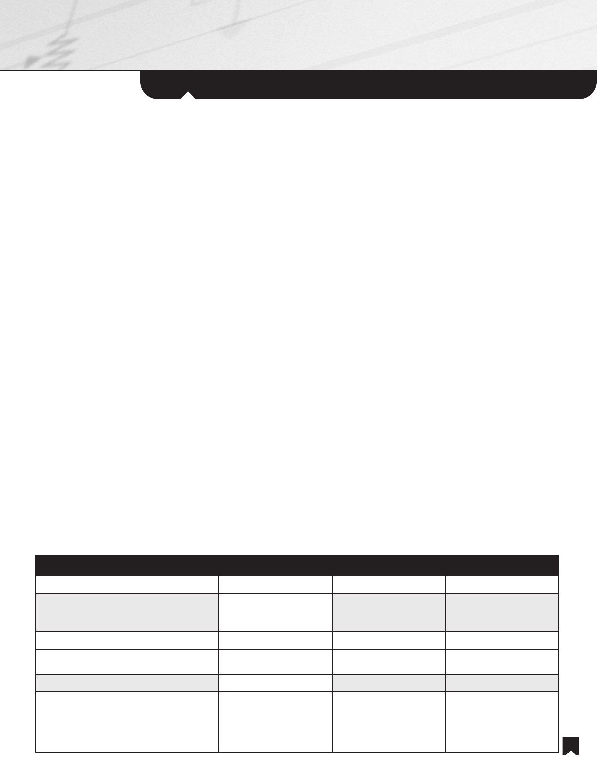
System NHS-3020 NHS-2020 NHS-1020
Plywood Box, minimum support capacity 400 pounds 325 pounds 275 pounds
Plywood Box, typical dimensions 12” minimum H x
19-1/8” W x
20-1/2” D
12” minimum H x
19-1/8” W x
20-1/8” D
12” minimum H x
19-1/8” W x
20-1/8” D
Rack Opening, width 19-5/8” 19-5/8” 19-5/8”
Rack Opening, minimum height, as measured
from top of plywood box 70-1/2” (70-5/8”” if using
the supplied threaded feet) 58-5/8” (58-3/4” if using
the supplied threaded feet) 47-7/8” (48” if using the
supplied threaded feet)
Rack Opening, minimum depth 26-1/2” 26-1/2” 26-1/2”
Rack Dimensions (NOTE: for close-tolerance
cabinetry, please measure the dimensions of
the actual rack itself. Sony will not be
responsible for the design inaccuracies of
enclosures.)
70-1/8” H x
19-1/8” W x
20-1/2” D
58-1/4” H x
19-1/8” W x
20-1/2” D
47-1/2” H x
19-1/8” W x
20-1/2” D