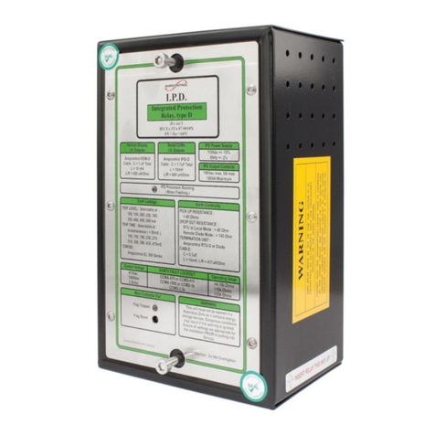
Ampcontrol IPM V2 User manual

Part Number: 121549
Revision: 12 –August 2014
Designed and manufactured in Australia by Ampcontrol Electronics Pty Ltd
IPM V2 –INTEGRATED PROTECTION RELAY
User Manual

IPM2B003 18/12/2014 10:247/08/2014 12:59 Page 2 of 37
Ampcontrol Electronics Pty Ltd –ABN 35 000 770 141
IPM2B003 IPM V2 User Manual
Rev 12 –08/14
WARNING!
This safety alert symbol identifies important safety messages in this
manual and indicates a potential risk of injury or even death to
personnel. When you see this symbol, be alert, your safety is
involved, carefully read the message that follows, and inform other
operators.
CAUTION!
This safety alert symbol identifies important information to be read in
order to ensure the correct sequence of work and to avoid damage or
even destruction of the equipment, and reduce any potential risk of
injury or death to personnel.
Supplementary information not directly affecting safety or damage to
equipment. Carefully read the message that follows, and inform other
relevant personnel.
Information concerning possible impact on the environment and
actions required for prevention and proper response.

IPM2B003 18/12/2014 10:247/08/2014 12:59 Page 3 of 37
Ampcontrol Electronics Pty Ltd –ABN 35 000 770 141
IPM2B003 IPM V2 User Manual
Rev 12 –08/14
Copyright Notice
The Ampcontrol IPM V2 described in this document is the property of AMPCONTROL PTY LTD. It is
furnished under a license agreement and is to be used only in accordance with the terms of the
agreement.
No part of the hardware or documentation may be reproduced, transmitted, transcribed, stored in a
retrieval system, or translated into any language or computer language, in any form or by any means,
without prior written permission of AMPCONTROL PTY LTD.
Disclaimer
While every effort has been made to assure the accuracy and clarity of this document, AMPCONTROL
PTY LTD assumes no liability resulting from any omissions in this document, or from misuse of the
information obtained herein. The information in this document has been carefully checked and is
believed to be entirely reliable with all of the necessary information included. AMPCONTROL PTY LTD
reserves the right to make changes to any products described herein to improve reliability, function, or
design, and reserves the right to revise this document and make changes from time to time in content
hereof with no obligation to notify any persons of revisions or changes. AMPCONTROL PTY LTD does
not assume any liability arising out of the application or any use of any product or circuit described
herein; neither does it convey license under its patent rights or the rights of others.
Before You Begin
We would like to take a moment to thank you for purchasing the Ampcontrol IPM V2 Integrated
Protection Relay.
WARNING!
To become completely familiar with this equipment and to
ensure correct operation, we strongly recommend that you
take the time to read and thoroughly understand this user
manual.
Ampcontrol Electronics Contact Details
7 Billbrooke Close, Cameron Park, NSW, 2285
P +61 2 4903 4800 | F +61 2 4903 4888
EMAIL: electronicsorders@ampcontrolgroup.com
WEB: www.ampcontrolgroup.com

IPM2B003 18/12/2014 10:247/08/2014 12:59 Page 4 of 37
Ampcontrol Electronics Pty Ltd –ABN 35 000 770 141
IPM2B003 IPM V2 User Manual
Rev 12 –08/14
TABLE OF CONTENTS
1 SAFETY AND OTHER WARNINGS..................................................................6
1.1 Safe Use of Equipment ..............................................................................6
2 RECEIVING AND STORAGE............................................................................7
2.1 Receiving...................................................................................................7
2.2 Inspection ..................................................................................................7
2.3 Storage after Delivery ................................................................................7
2.4 Unpacking of Equipment............................................................................7
3 INSTALLATION.................................................................................................8
3.1 General Warnings......................................................................................8
3.2 Mandatory Installation Practices ................................................................8
4 IPM V2 RELAY OVERVIEW............................................................................10
4.1 Protection Functions ................................................................................10
4.2 Basic Display Operation...........................................................................11
4.3 Trip/Status Messages ..............................................................................12
4.4 Last Trip Status Messages ......................................................................13
4.5 Machine Data Transfer ............................................................................14
5 EARTH PROTECTION FUNCTIONS ..............................................................15
5.1 Earth Leakage .........................................................................................15
5.2 Insulation Test .........................................................................................16
5.3 Earth Continuity .......................................................................................18
6 CURRENT RELATED FUNCTIONS................................................................19
6.1 Overload Protection .................................................................................19
6.2 Short Circuit Protection ............................................................................20
6.3 Phase Current Balance............................................................................20
6.4 Residual Current Signal ...........................................................................21
6.5 Under Current Trip...................................................................................21
7 VOLTAGE RELATED FUNCTIONS ................................................................22
7.1 Main Contactor Fail Protection.................................................................22
7.2 Undervoltage Trip ....................................................................................22
7.3 Voltage Metering......................................................................................22
8 OPERATION SUMMARY ................................................................................23
8.1 Analogue Output......................................................................................23
8.2 Communications ......................................................................................23
8.3 IPM Alarm Functions................................................................................24
8.4 Fan Control..............................................................................................24
8.5 Snore Function ........................................................................................25
8.6 Remote IPM Control ................................................................................26
8.7 Adjustable Settings ..................................................................................28
8.8 System Control ........................................................................................30
8.9 Event Log ................................................................................................31
8.10 Time and Date .......................................................................................33
9 SERVICE, MAINTENANCE & DISPOSAL.......................................................34
9.1 Commissioning and Calibration ...............................................................34
9.2 Equipment Service...................................................................................34
9.3 Equipment Maintenance ..........................................................................34

IPM2B003 18/12/2014 10:247/08/2014 12:59 Page 5 of 37
Ampcontrol Electronics Pty Ltd –ABN 35 000 770 141
IPM2B003 IPM V2 User Manual
Rev 12 –08/14
9.4 Disposal...................................................................................................35
10 SPECIFICATIONS ........................................................................................36
11 EQUIPMENT LIST ........................................................................................37
APPENDIX
1 IPM Earth Leakage Tripping Curves..................................................................2
1.1 Tripping Curves for Instantaneous Trip Time Setting .................................2
1.2 Tripping Curves for 25mA Trip Level Setting..............................................2
2 IPM Full Load Current Selection Table (100:1 CT) ............................................3
3 IPM Full Load Current Selection Table (1000:1 CT) ..........................................4
4 IPM Menu Structure ..........................................................................................5
5 IPM Modbus Address Table ..............................................................................7
6 Drawings .........................................................................................................10

IPM2B003 18/12/2014 10:247/08/2014 12:59 Page 6 of 37
Ampcontrol Electronics Pty Ltd –ABN 35 000 770 141
IPM2B003 IPM V2 User Manual
Rev 12 –08/14
1 SAFETY AND OTHER WARNINGS
For safety reasons, the IPM V2 must be installed, operated and serviced only by competent personnel.
Read and understand this instruction manual completely before installing, operating or servicing this
equipment. Failure to install or operate this instrument in accordance with the instructions contained in
this manual may create hazardous operating conditions.
1.1 Safe Use of Equipment
The equipment supplied has been manufactured according to the state of the art, and designed to
ensure a safe operation. The equipment may only be used within the design parameters.
The instructions within this manual must be observed as an aid towards achieving maximum safety
during operation.
The owner/user is responsible for observing the following instructions:
1.1.1 Changes to Equipment
Changes in the design and modifications to the equipment are not permitted. Unauthorised changes
made to the hardware or operating firmware will void the manufacturer's warranty, and may
compromise the integrity of the system into which it is installed and other connected equipment.
1.1.2 Equipment Knowledge
Experience with, or understanding of, this equipment is essential for the safe installation and removal of
the equipment. Therefore, in case of a question on how to safely proceed, contact Ampcontrol
immediately.
1.1.3 Manual Handling
Precautions have been taken to ensure all equipment is safe to handle and free from sharp edges.
However care should always be taken when handling enclosures and gloves should be worn.
1.1.4 Installation
Correct operation and safety depend on the IPM V2 and associated equipment being installed correctly.
Mechanical and or electrical installation and maintenance of plant and equipment must only be carried
out by appropriately qualified personnel and must be tested thoroughly prior to operation.
1.1.5 Operation
As safety depends on the IPM V2 functioning correctly it is highly recommended that all safety functions
of the IPM V2 be periodically tested to ensure correct operation.

IPM2B003 18/12/2014 10:247/08/2014 12:59 Page 7 of 37
Ampcontrol Electronics Pty Ltd –ABN 35 000 770 141
IPM2B003 IPM V2 User Manual
Rev 12 –08/14
2 RECEIVING AND STORAGE
2.1 Receiving
All possible precautions are taken to protect the equipment against damage or losses during shipment,
however before accepting delivery, check all items against the packing list or bill of loading. If there are
shortages or evidence of physical damage, notify Ampcontrol immediately.
Notify Ampcontrol within 7 days (maximum) in case of shortages or discrepancies, according to the
packing list. This action will help ensure a speedy resolution to any perceived problems. Keep a record
of all claims and correspondence. Photographs are recommended.
Where practicable do not remove protective covers prior to installation unless there are indications of
damage. Boxes opened for inspection and inventory should be carefully repacked to ensure protection
of the contents or else the parts should be packaged and stored in a safe place. Examine all packing
boxes, wrappings and covers for items attached to them, especially if the wrappings are to be discarded.
2.2 Inspection
Equipment that is found to be damaged or has been modified away from its published specification must
not be used. Please contact Ampcontrol if the equipment is suspected to be different than that ordered
or if it does not match the published specifications.
2.3 Storage after Delivery
When the equipment is not to be installed immediately, proper storage is important to ensure protection
of equipment and validity of warranty.
All equipment should be stored indoors, preferably on shelves and protected from the elements.
2.4 Unpacking of Equipment
The method of packing used will depend on the size and quantity of the equipment. The following
cautions should be interpreted as appropriate.
CAUTION!
Take care when unpacking crates as the contents may have shifted
during transport.
The disposal of packaging materials, replaced parts, or components
must comply with environmental restrictions without polluting the
soil, air or water.
Ensure that any timber and cardboard used as packaging is disposed
of in a safe and environmentally responsible manner.
Where possible, dispose of all waste products i.e. oils, metals, plastic
and rubber products by using an approved recycling service centre.

IPM2B003 18/12/2014 10:247/08/2014 12:59 Page 8 of 37
Ampcontrol Electronics Pty Ltd –ABN 35 000 770 141
IPM2B003 IPM V2 User Manual
Rev 12 –08/14
3 INSTALLATION
3.1 General Warnings
These instructions have been designed to assist users of the IPM V2 relay with installation.
Before the IPM V2 can be installed, there are a number of things that need to be considered and
understood to prevent incorrect or unsafe operation of the relay or the system into which it is installed.
Along with relevant competence, and an understanding of the target application, the following points
should be considered:
3.1.1 Ensure that the information provided in this user manual is fully understood.
It is extremely important that the limitations and functionality of the IPM V2 are understood to prevent
incorrect installation and use from creating a potentially dangerous risk. If in doubt as to the nature of the
limitations or their implication, consult a competent authority such as a supervisor or Ampcontrol
technical representative.
3.1.2 Ensure that the application into which the relay is being installed has been properly
defined, designed and approved.
Any system intended to mitigate the risk of injury needs to be properly designed and implemented. Such
a system must be the result of structured risk analysis with the outcomes used to define the system
requirements. These requirements, in turn, will guide the choice of instrumentation, logic solvers and
actuators needed to implement the system. Understanding the needs of the system will ensure proper
selection of equipment.
3.1.3 Ensure that the relay will properly perform the required functions within the system design.
It is important to understand how the IPM V2 is intended to interact with other equipment within a
system. For safe and reliable use, it is crucial that neither the relay’s logical operation nor its signalling
be compromised by incompatibilities with connected equipment.
3.1.4 Modifications of any form to the IPM V2 relay are prohibited.
The IPM V2 as supplied has been designed and manufactured to comply with the requirements of
protection standards. If modifications of any form are made to the relay, the equipment may no longer be
fit for use. If any modifications or damage to the relay is evident, do not use the equipment and contact
Ampcontrol for advice.
3.2 Mandatory Installation Practices
The following information must be adhered to when installing the IPM V2. Failure to adhere to this
information may give rise to unsafe operation.
Using the IPM V2 in a manner that exceeds its electrical, functional or physical specifications, or in a way
that is contrary to its operating restrictions, may create risks to personnel and/or equipment resulting in
injury or death.
The relay must be powered within the specified voltage range.
The installation of the relay must be carried out by suitably trained and qualified personnel.
Identification labels fixed to the relay must not be damaged, removed or covered before, during or
after installation.
The installation is to be in accordance with the relevant installation Standards/Codes of Practice.

IPM2B003 18/12/2014 10:247/08/2014 12:59 Page 9 of 37
Ampcontrol Electronics Pty Ltd –ABN 35 000 770 141
IPM2B003 IPM V2 User Manual
Rev 12 –08/14
Modifications must not be made to any part of the IPM V2. As supplied, the unit is built to, and
complies with the relevant standards. Modifications to its construction will render the unit non-
compliant.
Complete and accurate records of the installation must be kept as part of the site installation.

IPM2B003 18/12/2014 10:247/08/2014 12:59 Page 10 of 37
Ampcontrol Electronics Pty Ltd –ABN 35 000 770 141
IPM2B003 IPM V2 User Manual
Rev 12 –08/14
4 IPM V2 RELAY OVERVIEW
The Ampcontrol IPM Integrated Protection Relay (Version IPM V10.0) is an intelligent protection relay
based on microprocessor technology. The IPM Integrated Relay provides the necessary functions
required for protecting electrical outlets supplying underground mining machinery, powered by reeling or
trailing cables, in the metalliferous industry. The relay can also be used to provide optimum overload
protection of motors used on conveyors, pumps, fans and compressors. All of the protection functions
are combined into a compact, plug-in unit, which can be easily changed out to minimise down time in the
event of a problem with the relay.
The IPM Integrated Protection Relay can provide Machine Data Transfer through the use of a Remote
Termination Module (RTM) connected between the pilot and earth at the machine end of the trailing
cable. Through the use of the RTM Remote Termination Module the relay parameters are automatically
up loaded from a remote machine when a cable is inserted into a power outlet. The RTM also allows for
remote control (starting) of the IPM output.
A RS485 Modbus communication port is available that can be connected to Motor Starter PLC's or a
central monitoring system for continuous monitoring and fault-finding.
The IPM Relay provides an isolated 4-20mA analogue output to continuously monitor Average Current,
Overload, Earth Leakage and the Insulation level of the relay.
An automatic Insulation Test can be initiated once all starting conditions are met. A high voltage DC
“Insulation Test” to earth of the cable is carried out. If the result of the Insulation Test is above the preset
resistance level, the IPM’s MCR relay energises, which in turn closes the main contactor. A manual
“Insulation Test” is provided as a maintenance/fault finding tool (when this test is performed the MCR
relay does not close at completion of a healthy test). The Insulation Test allows cable insulation levels to
be trended as an aid to preventative maintenance.
The Burp Function allows for the progressive inflation of ventilation bags (tubes) by pulsing the motor
contactor controlling a ventilation fan, several times at start up.
The Snore Function is available for controlling pumps; the Snore function automatically stops the output
on detection of low current and restarts the outlet after a fixed or automatically-adjustable time delay.
The IPM Integration Protection Relay has 6 digital inputs, which feed into a microprocessor unit. The
microprocessor has been programmed to control three output relays. The relays are MCR (Main
Contactor Relay), CBR (Circuit Breaker Relay) and ALM (Alarm Relay).
All of the tripping logic and outlet control is performed by the microprocessor, so that virtually no external
control is required.
A four-line 20 character backlit LCD display combining with a keypad provides an easy to operate user
interface. The display provides easy access to all available information. A simple procedure allows
adjustment of the relay’s settings.
4.1 Protection Functions
The IPM Integrated Protection Relay provides protection functions for:
Earth Leakage
Earth Continuity
Overcurrent
Short Circuit
Under Current
Contactor Fail
Under Voltage
Protection trips are stored in a non-volatile memory requiring a reset function before power can be
restored to the load. This remains the case even if a power down occurs following a trip condition.

IPM2B003 18/12/2014 10:247/08/2014 12:59 Page 11 of 37
Ampcontrol Electronics Pty Ltd –ABN 35 000 770 141
IPM2B003 IPM V2 User Manual
Rev 12 –08/14
4.2 Basic Display Operation
The fascia of the IPM Integrated Protection Relay has a four line 20 character backlit Liquid Crystal
Display (LCD), Status LED and a tactile keypad. Figure 1 gives an overview of the fascia of the relay.
Figure 1: IPM Relay Fascia and Display
The layout of the display structure is shown on the ‘IPM Display Map’. The display level is changed with
the Up/Down arrow keys and the Left/Right arrow keys control the various display screens.
The ENT and ESC keys are used to modify settings and provide hyper jump access to the display
structure.
The Reset key allows a reset following a trip condition.
The Test key is used to activate a manual insulation test.
Start and Stop keys are provided for closing and opening the main contactor supplying power to a
machine.
The Status LED is a single bi-coloured LED that can be viewed some distance from the relay. Status
indication is as follows:
IPM Status
LED Colour
LED Flash
OK (Run)
Green
4Hz
OK (Stopped)
Green
1Hz
Alarm
Red
4Hz
Trip
Red
1Hz
The IPM status display is one of the most useful features of the relay’s display system and should be
viewed as the first step in fault finding. The ‘Relay Status Page’ is the default screen on power up and
shows the current status of the IPM Protection Relay.
[ Need IPM Start ]
Load [Pump # 1 ]
I= 0 Amps V= 0 V

IPM2B003 18/12/2014 10:247/08/2014 12:59 Page 12 of 37
Ampcontrol Electronics Pty Ltd –ABN 35 000 770 141
IPM2B003 IPM V2 User Manual
Rev 12 –08/14
Line 1: A one-line status message is displayed and if more than one message is active the
display cycles through all active messages at 1 second intervals.
Line 2: IPM Software version appears here while the UP arrow key held.
Line 3: Shows the Load Type and Number (from the connected RTM unit).
Line 4: Shows the Load Current (3ϕaverage) and Load Voltage (average ϕ- ϕ.)
Through the use of the Modbus communications port, PLC’s and SCADA systems can be configured to
display the same messages that appear on the display. This helps to provide consistent information to
operators.
4.3 Trip/Status Messages
The following table shows a list of the forty (40) status messages and the category (type) of the
messages. Messages are cleared according to their message category.
Type 1: Messages are latched for display and are cleared by either pressing the <ENT> key
while on the Status Display Page or by starting a new starting sequence.
Type 2: Messages are enabled and cleared automatically.
Type 3: Messages are triggered by the respective trip functions and are cleared by resetting the
trip function.
Message and Type
Comment
Tripped No Volts
1
Voltage on load side of contactor is too low
MC Close Fail
1
MCI input did not close within 5 sec of MCR relay
closing
External MC Open
1
IPM detected (via MCI input) that MC was opened –
not initiated by the IPM relay
Burp MCI Fail
1
MCI input fails to follow MCR relay output during burp
phase
Under Current Trip
1
Under Current function tripped
Last T:--------
1
Shows ‘Last Trip’ record
Outlet Paused
2
IPM waits 5 sec between running (or testing) and re-
testing
Need IPM Start
2
Awaiting IPM start digital input
Testing Insulation
2
In process of Insulation Test (2 seconds)
Closing Main Cont.
2
MCR closed, waiting on MCI feedback (5 sec max.)
Burp: MCR Closed
2
Burp Phase is on MCR closed
Burp: MCR Open
2
Burp phase is active –MCR is open
Running
2
Outlet closed
Snore
2
Snore function active
Snore –Close AUX
2
Aux digital input must be closed for Snore to function
High Current Alarm
2
High Current Alarm triggered
Thermal Trip Alarm
2
Thermal Trip Alarm triggered
Cur. Balance Alarm
2
Current Balance Alarm triggered
Under Cur. Alarm
2
Under Current Alarm triggered
Earth Leakage Alarm
2
Earth Leakage Alarm triggered
UnderVoltage Alarm
2
Under Voltage Alarm triggered
Insulat. Test Alarm
2
Insulation Test Alarm triggered
Earth Leakage Trip
3
Earth Leakage function tripped
Earth Cont. Trip
3
Earth Continuity function tripped
Insulat. Fail Trip
3
Insulation Test function tripped
Over Current Trip
3
Over Current function tripped
Short Circuit Trip
3
Short Circuit function tripped
I Balance Trip
3
Phase Current Balance function tripped

IPM2B003 18/12/2014 10:247/08/2014 12:59 Page 13 of 37
Ampcontrol Electronics Pty Ltd –ABN 35 000 770 141
IPM2B003 IPM V2 User Manual
Rev 12 –08/14
Residual Cur. Trip
3
Residual Current function tripped
Main Contactor Fail
3
Main Contactor Fail function tripped
RTM-Offline Trip
3
IPM cannot communicate with RTM
IPM Memory Error (see
Note 1)
3
Corrupted memory in relay’s stored settings
RTM Memory Error (see
Note 1)
3
IPM detected errors in set up data received from RTM
Stopped - IPM
3
IPM Stop digital input activated (closed)
RTM CT Ratio Error (see
Note 2)
3
The attached RTM was set up using a different CT
ratio than that of the IPM in use
RTM Version Error
3
The attached RTM does not support 100:1 CT
operation
Need RTM Start
2
Shown when the digital input it closed but the IPM is
stopped
Remote Stop
3
Shown whenever RTM’s digital input is open
Configuration Error
2
Present when:
Start is set to Modbus.
In snore mode; the delay or undercurrent trip level is
not set. Also if the remote start is set to ‘yes’ or ‘aux’
whilst in snore mode.
Stopped –Ext Stop
3
IPM Stop digital input externally activated (closed).
1. It is normal to see the IPM Memory Error Message when
switching between Diode/RTM Mode or when the RTM is first
connected to the pilot.
2. If the CT Ratio is changed the current setting must also be
reset (otherwise an Error Message of "RTM CT Ratio Error" will
be displayed).
4.4 Last Trip Status Messages
The IPM Relay has several functions, which can stop/trip the outlet and then self-clear. The IPM Relay
therefore saves the non-latched trip codes in a register and displays the ‘Last Trip’ messages in the
Status Message Page (note that the stop/trip function also appears in the Event Log).
Messages that are displayed at Last T: ---------
Message and Type
Comment
EC Leak T
E/C Leakage Trip that provides additional
information for E/C Trip
EC Ω Trip
E/C Ohms Trip that provides additional
information for E/C Trip
MC Opened
Main contactor opened –opening not initiated
by the IPM Relay
RTM Off L
RTM Off Line –IPM cannot communicate with
RTM
Und. I Trp
Under Current trip caused outlet to stop
Stopped
IPM Stop Input Tripped Locally
Ext. Stop
IPM Stop Input Tripped Externally

IPM2B003 18/12/2014 10:247/08/2014 12:59 Page 14 of 37
Ampcontrol Electronics Pty Ltd –ABN 35 000 770 141
IPM2B003 IPM V2 User Manual
Rev 12 –08/14
4.5 Machine Data Transfer
4.5.1 Remote Termination Module
The Remote Termination Module is a microprocessor based fully encapsulated module that replaces the
diode at the end of the pilot conductor of the trailing cable. It is powered by and communicates via the
pilot line. Its non-volatile memory stores the parameters to configure the outlet as appropriate for that
machine.
Machine type and machine number are displayed on the Default and Earth Continuity Screens (Levels 1
and 3).
4.5.2 Machine Type Codes
There are fourteen (14) selectable machine type codes available for use in the Remote Termination
Module. The descriptive code is transmitted to the IPM Relay to identify the type of machine connected
to the outlet. The codes are programmed at the ‘RTM Mach. Type’ page (Level 6, Screen 1).
J-bo Face Boring Machine
Fan Ventilation Fan
Drill Drill
Pump Pump
Hpmp Hydraulic Pump
Wpmp Water Pump
DCB Distribution Control Box
Bolt Bolter
HRMr Hard Rock Miner
Belt Conveyor Belt
Winc Winch
Crsh Crusher
Dplg Dummy plug
Spare
4.5.3 Machine Type Number
Machine numbers 1 to 40 can be assigned to machines. These numbers are programmed at the ‘RTM
Mach. Num.’ page (Level 6, Screen 2).

IPM2B003 18/12/2014 10:247/08/2014 12:59 Page 15 of 37
Ampcontrol Electronics Pty Ltd –ABN 35 000 770 141
IPM2B003 IPM V2 User Manual
Rev 12 –08/14
5 EARTH PROTECTION FUNCTIONS
5.1 Earth Leakage
5.1.1 Introduction
Protection systems are defined in AS/NZS 2081 for use in fault limited systems. This standard describes
the requirements of Earth Leakage protection to initiate a trip of the circuit interrupting device when a
selected value of earth fault current is exceeded for a certain amount of time.
All protection systems must comply with this standard as stated in AS/NZS 4871, which sets out the
general requirements for the design, construction and testing of electrical equipment directly associated
with mining and quarrying activities. Part of these requirements includes designing for electrical faults,
and the standard outlines the safe touch potential which must be considered in electrical protection
design. Acceptable touch potential levels are described using a series of curves as shown in Figure 2.
Figure 2: AS/NZS 4871 Safe Touch Potential Levels (Figure C1 from the standard)
The IPM V2 relay Earth Leakage protection function has been designed in accordance with AS/NZS
3190 –Approval and Test Specification –Residual current devices (current-operated earth-leakage
devices). Given this, it is important to consider the performance of the Earth Leakage protection
provided by the IPM V2 and assess how the relay’s performance compares with the requirements of
AS/NZS 2081. Testing was completed to assess the ability of the IPM V2 relay to trip within acceptable
levels.
The results for the Earth Leakage tripping times of the relay are detailed in Appendix 1. These results
show the tripping times are well within those specified by the relevant standards. The tripping times
reduce for higher fault currents, improving the performance of the relay. Figure 3 summarises the trip
times which can be expected when the trip time is set to be ‘Instantaneous’, for increasing fault currents
at different trip levels.

IPM2B003 18/12/2014 10:247/08/2014 12:59 Page 16 of 37
Ampcontrol Electronics Pty Ltd –ABN 35 000 770 141
IPM2B003 IPM V2 User Manual
Rev 12 –08/14
Figure 3: Instantaneous trip times for a selection of device trip level settings
5.1.2 Earth Leakage Protection Function
The Earth Leakage protection function uses a 1000:1 core balance toroid to measure the earth fault
current. A Residual Current Device (RCD) operating characteristic is provided with adjustable trip
sensitivity and time delay.
The % leakage current is displayed on the 'Current and Voltage Information’ page (Level 2, Screen 2) as
‘Ie’ shown as a % of the selected trip level. When the leakage reaches 100% a trip occurs. For timing of
the trip refer to Appendix 1. As discussed above the higher the fault current measured, the faster the trip
response.
To reset the relay following an earth leakage trip, operate the reset key/digital input.
The trip level is selected via the ‘RCD Trp. Level’ setting (Level 6, Screen 13) and is adjustable between
25mA and 500mA and off.
The time delay is selected via the ‘RCD Trp. Time’ setting (Level 6, Screen 14). Settings are
Instantaneous and adjustable settings between 50ms and 150ms.
5.2 Insulation Test
The IPM Relay can provide an automatic High Voltage ‘Insulation Test’. A manual ‘Insulation Test’ is
also provided.
An insulation test module, which is a resistive isolation device, is used to interface the power conductors
to the IPM Relay. Modules are selected in the Group 1 Settings ‘ITM Module’ (Level 5, Screen 2) for
rated line voltages of 415V and 1000V.
The IPM Insulation Test Module (ITM) is the preferred isolation module and must be used when the
‘Insulation Test’ function is required.
When “None” is selected the IPM Relay does not provide ‘Insulation Test’, or voltage functions.
5.2.1 Automatic Insulation Test
If an ITM Module has been selected, in the adjustable Group 1 Settings and a trip level has been set in
the adjustable Group 2 settings, then an automatic High Voltage DC ‘Insulation Test’ is initiated by
operation of the start button once all starting conditions are met.
The HV DC ‘Insulation Test’ commences when the IPM Relay applies voltage to the V Test terminal of
the relay for a period of 2 seconds. This applies 30VDC to the ITM Module. A HV DC voltage is
generated in the ITM Module, which applies a voltage of 500V for 415V operation and 820V for 1000V
systems, between each phase and earth.
0
50
100
150
200
250
300
100 1000
Trip Time (ms)
Fault Current (mA)
25mA
50mA
100mA
200mA
500mA

IPM2B003 18/12/2014 10:247/08/2014 12:59 Page 17 of 37
Ampcontrol Electronics Pty Ltd –ABN 35 000 770 141
IPM2B003 IPM V2 User Manual
Rev 12 –08/14
The IPM Relay measures the voltage on the line and calculates the resistance to earth for all phases. At
the end of the test the result is stored in the Event Log as ‘It:X.XMΩ’ If the resistance value is above the
preset threshold the MCR Relay picks up allowing the outlet to be energised. Additionally, if the result is
equal to or below an Alarm Level (typically 1.5 times the selected trip level) the status message
‘Insulat.Test Alarm’ is displayed on the Status Page (Level 1, Screen 1).
Ins. Tst. Level: Selection MΩ
Alarm Level MΩ
1.0
1.5
2.0
3.0
5.0
7.5
10
15
20
30
None
None
If the value is less than the preset trip level a trip occurs and is latched and saved in a non-volatile
memory. To reset the relay following an insulation test fail trip, operate the reset button.
L3: Indicates the status of the insulation test.
L4: Displays the insulation resistance as a result of the test and is retained in memory until the
next test is carried out.
The trip level is set at ‘Ins.Tst.Level’ page (Level 6, Screen 18) and is selectable.
If the ‘Insulation Test’ is not selected by setting the ‘ITM Module’ value to “None”then the MCR Relay
closes by operation of the start button.
5.2.2 Manual Insulation Test
A manual “Insulation Test” is provided as a maintenance/fault finding tool. The manual test can only be
carried out when the load is not energised. A manual insulation test is also prevented when operating in
snore mode.
Before a manual Insulation Test can be performed the following conditions must apply:
1. The Insulation Test page being displayed. This is located on the ‘Insulation Test’ screen (Level 3,
Screen 2).
2. Pilot must be healthy (and any previous trips reset).
3. Insulation Test function must not be tripped.
4. Outlet must not be running.
5. Outlet must not be in the process of ‘closing’.
6. Outlet must not be ‘Paused’
When the above conditions are met the <TEST> key must be pressed and held (for the duration of the
test). After 3 seconds the manual insulation test is initiated. The test voltage is applied to the outgoing
feeder while ever the above conditions are held (including holding the <TEST> key). The test results are
continuously calculated and displayed. The operator should maintain the test at least long enough for the
readings to stabilise, this being a function of the cable length. Once the test is completed (usually by
releasing the <TEST> key) the results are held in memory until another insulation test is commenced
either manually or as part of the starting sequence, or IPM control power is lost.
If the ‘ITM Module’ has been set to “None” then the manual test will not function.
The status of the manual insulation test is shown on the Insulation Test Screen (Level 3, Screen 2).
Insulation Test 3
---- Not Active ----
Last Test : 8.6MΩ

IPM2B003 18/12/2014 10:247/08/2014 12:59 Page 18 of 37
Ampcontrol Electronics Pty Ltd –ABN 35 000 770 141
IPM2B003 IPM V2 User Manual
Rev 12 –08/14
The three functions shown on the screen are ‘Not Active’, ‘Arming Man.Ins.Test’ and ‘Manual Insulat.
Test’.
The display will show the last measured value.
5.3 Earth Continuity
The Earth Continuity function tests for the continuity of the earthing between the outlet and the machine,
via the pilot core in the trailing cable. The pilot core is also used to transfer data when a Remote
Termination Module is used to achieve Machine Data Transfer.
The IPM relay can be configured to operate in either diode or RTM mode. The mode is selected in ‘EC
Pilot Mode’ (Level 5, Screen 1) and determines what terminating device the relay is looking for on the
pilot.
The Remote Termination Module will only be recognised by an IPM
Relay and will not be seen as a diode by other earth continuity
devices.
The relay measures the resistance of the pilot - earth loop and the leakage between the pilot and earth
conductors. The leakage measurement ensures that pilot to earth faults is detected. If the pilot - earth
loop resistance exceeds 45Ω a trip occurs which in turn opens the main contactor control circuit. The
fault can be configured as latching or non-latching. This allows the user to determine if the fault is
manually or automatically reset once the pilot - earth loop resistance is less than 45Ω. The selection is
either ‘EC Trip Latch: On’ or ‘Off” (Level 6, Screen 17). To manually reset the relay, operate the reset
button.
L3: Shows the earth continuity resistance (R) of the pilot –earth loop and the leakage (L)
between the pilot and earth conductors as a % of the trip levels. When either value reaches
100% a trip occurs. The version of the software is also indicated.
L4: Shows the Load Type and Number (from the connected RTM unit).
Pilot Trip Time is adjustable to allow for operation in noisy electrical environments. The trip times can be
selected at ‘Pilot Trip t’ (Level 6, Screen 15) and can be set to 80, 120, 160, 200, 300, 400 and 500ms.
A setting of 120ms should be suitable for most installations. Long time delays (>200ms) should only be
used where necessary. Consequence of long trip times should be thoroughly assessed from a safety
point of view before using the higher values.
The leakage trip setting is fixed at 1850Ω.
Earth Continuity 3
R:27% L: 0% V#10
Load [WPump # 1]

IPM2B003 18/12/2014 10:247/08/2014 12:59 Page 19 of 37
Ampcontrol Electronics Pty Ltd –ABN 35 000 770 141
IPM2B003 IPM V2 User Manual
Rev 12 –08/14
6 CURRENT RELATED FUNCTIONS
6.1 Overload Protection
The motor overload function is based on a thermal model of the motor. The three phase currents are
squared to provide the I2R heating input to the motor model. The selected ‘Stopped Cooling Ratio’
determines the cooling output for the model.
The state of the thermal model is shown by the ‘Thermal Accumulator’, which can be viewed on the
'Current/Volts Information' level on the display. The thermal accumulator represents the motor
temperature. When the accumulator reaches 100%, a Motor Overload Trip occurs.
The full load current is selected via the ‘100% Current’ setting (Level 6, Screen 2) and can be set
between 0.5125A and 640A in 448 steps. See the Appendix section of this manual for the respective Full
Load Current Selection tables for a 100:1 CT or 1000:1 CT.
The trip time is selected via the ‘O/L Trp t @ 6x’ setting (Level 6, Screen 6). It is a function of the current
and the selected trip time curve. Refer to Appendix 6 for details of the motor overload and short circuit
trip times.
The fifteen (15) motor overload curves allow trip settings from 3 to 40 seconds at six (6) times FLC and
are shown for both cold and hot conditions. The hot curve corresponds to the trip time after the motor
has been running at the selected full load current indefinitely.
The trip time can be calculated as follows:
Where:
C = Curve Selected
I = Current (FLC = 1)
A% = Initial Thermal Accumulator Value
For Cold Start A = 0% and on Hot Start, A = 89%.
The motor manufacturer's data should always be consulted to select the appropriate settings for the
motor being protected. Typically, the capacity of a cold motor is given at six times its rated current.
The IPM Relay's trip curves can then be used to select the trip time curve, which best suits the motors
overload capacity.
The motor overload trip latches once the thermal accumulator reaches 100% and can only be reset once
the thermal accumulator falls below a preset value. The preset value is selected via the ‘O/L Rst Level’
setting (Level 6, Screen 8) and can be set to 30%, 40%, 50%, 60%, 70%, 80%, 90%, A-30%, A-40%, A-
50%, A-60%, A-70%, A-80%, A-90%. The “A-“settings automatically reset a motor overload trip once the
thermal accumulator falls below the set value. Otherwise the trip has to be reset manually by pressing
the keypad ‘RESET’ button or activating the ‘RESET’ digital input once the thermal accumulator has
fallen below the set value.
An emergency restart on a hot motor can be achieved by zeroing the thermal accumulator memory. This
is done by closing the Lock input and Reset key/digital input simultaneously for 1.5 seconds.
1238.1
100
%1238.1
ln53.31
2
2
I
A
I
xCTimeTrip

IPM2B003 18/12/2014 10:247/08/2014 12:59 Page 20 of 37
Ampcontrol Electronics Pty Ltd –ABN 35 000 770 141
IPM2B003 IPM V2 User Manual
Rev 12 –08/14
CAUTION!
Repeated restart attempts in this condition may damage the motor.
The ‘Stopped Cooling Ratio’ modifies the cooling output of the thermal model when the motor is stopped.
This can be used to account for reduced cooling capacity of the motor when it is not running (motor run
status monitored via MCI digital input).
The ratio is selected via the ‘O/L cool mult’ setting (Level 6, Screen 7) and is adjustable from 1.0 to 5.0.
A cooling multiplier of 1 means the cooling is independent of whether the motor is running or not –for
example, a water-cooled motor. Protection for a fan-cooled motor is based on a setting of 2.5, however,
for the best protection consult the motor manufacturer.
6.2 Short Circuit Protection
The short circuit function has a definite time characteristic. If the current exceeds the selected level for
the pre-set time then a trip occurs. The short circuit function trips the CBR relay (the CBR relay is
normally energised, and drops out when tripped).
The short circuit trip level is selected via the ‘Short Cct.Trip’ setting (Level 6, Screen 4) and is a multiple
of the selected full load current, from 3.0 to 10 times FLC, in steps of 0.5. The trip time is selected via the
‘Short Cct. t’ setting (Level 6, Screen 5) and is adjustable from 20 to 160ms.
To reset the relay following a short circuit trip it is necessary operate the reset key/digital input.
6.3 Phase Current Balance
The current balance measurement ‘Ib’ is displayed on the ‘Voltage and Current Information’ page, Level
2, Screen 2.
If Iave is <100% the difference between the average current and each phase current is calculated. The
maximum difference is used as the current balance percentage.
If Iave is >= 100% then the current balance is calculated as:
𝐼𝑏𝑎𝑙 =
MAX ΔI x 100%
𝐼𝑎𝑣𝑒
Where:
Iave = Average of the 3 phase currents
MAX Δ I = The maximum deviation of a phase current from the average
Phase current balance protection is selected via the ‘Cur.Bal.trip’ setting (Level 6, Screen 9).
The trip level is selectable at 5%, 10%, 20%, 50% and OFF.
The phase current balance protection is inhibited until the average current exceeds both 20% of the
selected full load current and the selected balance trip level.
If any phase drops below the selected trip setting for a period of 2 seconds then the outlet is stopped. To
reset the relay following a current balance trip, operate the reset key/digital input.
Other manuals for IPM V2
1
Table of contents
Other Ampcontrol Relay manuals

Ampcontrol
Ampcontrol ELD V2 User manual

Ampcontrol
Ampcontrol ELD V2 User manual

Ampcontrol
Ampcontrol MAG-153 User manual

Ampcontrol
Ampcontrol ELV-PRO User manual

Ampcontrol
Ampcontrol IPM V2 User manual

Ampcontrol
Ampcontrol HPB User manual

Ampcontrol
Ampcontrol ELV-PRO RV User manual

Ampcontrol
Ampcontrol EFL User manual

Ampcontrol
Ampcontrol IPD User manual

Ampcontrol
Ampcontrol MPA3 V6.3 User manual