ELDB006R9 15/07/2015 17:44 Page 9 of 21
Ampcontrol Electronics
ELDB006R9 ELD V2 USER MANUAL
Rev 9 –03/14, ECN: 10573
4 OVERVIEW OF EARTH LEAKAGE PROTECTION
Earthing of electrical equipment, associated machinery and structures is a seemingly simple practice and
is covered adequately by the various applicable sections of Australian Standards AS3000 or AS3007.
However, in the mining industry earthing is somewhat more complex than normal domestic or
commercial applications and requires other factors to be taken into consideration, particularly where
trailing and/or reeling cables supply mobile electrical equipment. The protection systems are designed to
provide touch and step potentials of 50V or less when all the systems are used collectively.
It should be clearly understood that unless all four types of protection is incorporated in any design, then
personal protection (touch and step potentials of 50V or less) will need to be assessed by a competent
person or authority.
The protection systems that cover coal, shale mines and metalliferous mining are detailed in AS/NZS
2081:2011.
The above standard does not stand-alone and has been developed in coordination with other standards
being:
AS1740 –Underground mining substations.
AS1802, AS1300 - Reticulation, trailing and reeling cables.
AS1299, AS1300 - Plugs, adaptors, couplers and receptacles.
AS/NZS 4871 –Electrical Equipment For Mines And Quarries
Internationally accepted voltage/time effects on the human body based on IEC479.
Instructions for installation in accordance with accepted State and Federal Regulations.
Equipment maintained in accordance with industry standards.
4.1 Overview of Protection Problems
Unless properly controlled the occurrence of an earth fault can be hazardous because it may cause:
Frame to earth voltages dangerous to personnel.
Electric arcing, which may initiate an explosion or fire when arcing occurs in an underground
mining operation.
The main purpose of earth fault protection is to safeguard personnel and
electrical apparatus. However it is found that relays designed to operate on
fault limited systems are not suitable for direct personal protection, i.e.
users of portable drills, grinders etc, which require trip levels of 20-30mA,
with instantaneous operation. (Refer AS/NZS 3190).
The most common apparatus faults in mining applications are cable faults. Cables are most susceptible
to damage and are the major source of dangerous electrical incidents. This applies particularly to the
flexible trailing cables supplying power to mobile mining machines.
Cable construction is such as to provide every phase conductor with an individual conductor screen so
that crushing would cause a low single phase to earth fault current. The protective device, such as an
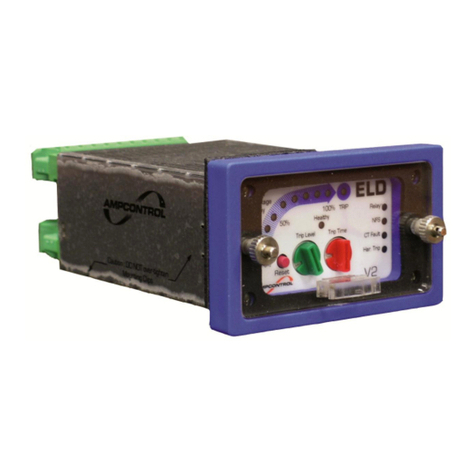
Ampcontrol ELD earth leakage relay, would then isolate the cable and contain the sparking within the
cable before a heavy short circuit current due to a phase to phase fault occurs.
Earth fault protection has been applied with considerable success in limiting faults and providing quick
disconnection of electrical apparatus from the supply in the event of earth fault situations.
