FI6000 | FIRE ALARM INTERFACE PAGE 7
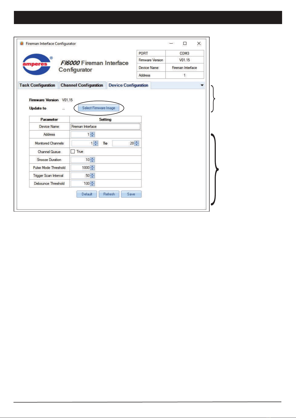
Device Setup (PC Interface)
3. Task Configuration
5 type of Tasks are available. Every triggered channel shall follow the same sequence of Task set.
Task type : Zone Selector
Activation of TD6240 or TD6080 shall be done using RS485. The parameters at this task type are :
Address
Type
Priority
Set No
Trigger slide
: refers to the unit address of the TD
: to trigger specific zone or ALL CALL, if “channel specific” is selected and channel configuration window is
required to specify zone
: priority setting of FI as compared with others, such as paging mic.
: the zone number of range of zones
: select to trigger or off the zones
Task type : Delay
Apply this task to insert delay in between tasks, measured in seconds.
2. Channel Configuration
There are 24 boxes, with each represent an input channel. Upon activation of each channel, the system shall look up to the
relevant box to obtain the data on which zone to trigger. (Diagram as at page 9)
Example : when channel 1 is active, it is required to trigger Zone 1,2,5,6 to 10. Thereby fill in the numbers as 1,2,5,6-10.
There are up to 10 zone groupings, which is useful to provide secondary or subsequent triggering if the fault is not restored.
Example ; when channel 1 is active, trigger zone 1,2,5,6 to 10, 11 to 15 and after the 10 min lapse ( set in Task Configuration tab
), if the fault is not attended to, it shall select second zone group such as 1,2,5,6 to 10, 15,20. Thereafter to ALL CALL.
Example:
Up to 255 tasks can be set for each channel. Ensure correct task sequence when doing the configuration. Upon completion, the
settings can be saved in a file and retrieved later on for editing or uploading to the unit.
Input
channel
Targeted
zone
Tick box to view
selected zone