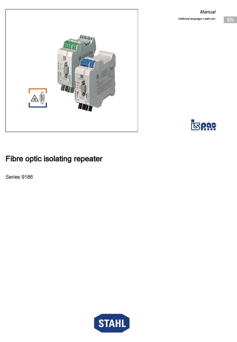
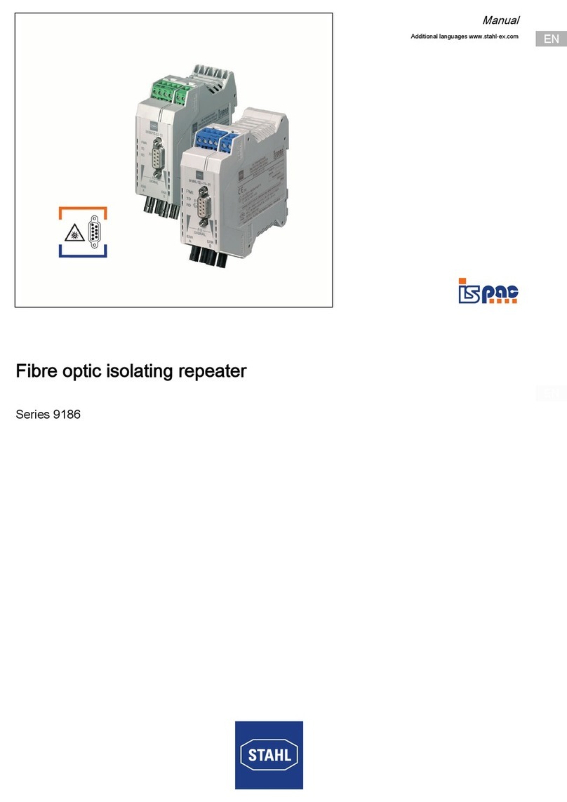
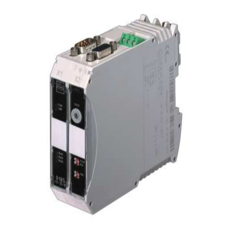
Stahl 9186 5-12-11 Series User manual

R. STAHL Schaltgeräte GmbH
Betriebsanleitung / Operating instructions
1 Allgemeine Angaben
1.1 Hersteller
R. STAHL Schaltgeräte GmbH
Am Bahnhof 30, 74638 Waldenburg, Germany, T: +49 7942 943-0, F: +49 7942 943-4333, www.r-stahl.com
1.2 Angaben zur Betriebsanleitung
ID-Nr.:167469 / 918660310040, Pub-Nr.: 2018-05-09•BA00•III•de•05,
Hardwareversion: 12, Softwareversion: 130
1.3 Weitere Dokumente
Handbuch 9186
Datenblatt
Weitere Sprachen, siehe www.r-stahl.com
1.4 Konformität zu Normen und Bestimmungen
Siehe EU-Konformitätserklärung: www.r-stahl.com
Das Gerät verfügt über eine IECEx-Zulassung. Siehe IECEx-Homepage: http://iecex.iec.ch/
Weitere nationale Zertifikate stehen auf der Internetseite www.r-stahl.com zum Download bereit.
2 Sicherheitshinweise
•Sicherheitshinweise in dieser Betriebsanleitung lesen und beachten!
•Gerät nur bestimmungsgemäß und nur für den zugelassenen Einsatzzweck verwenden.
•Für Schäden, die durch fehlerhaften oder unzulässigen Einsatz sowie durch Nichtbeachtung dieser
Betriebsanleitung entstehen, besteht keine Haftung.
•Vor Installation und Inbetriebnahme sicherstellen, dass das Gerät unbeschädigt ist.
•Arbeiten am Gerät (Installation, Instandhaltung, Wartung, Störungsbeseitigung) nur von dazu befugtem und
entsprechend geschultem Personal durchführen lassen.
•Bei Installation und im Betrieb die Angaben (Kennwerte und Bemessungsbetriebsbedingungen) auf Typ-
und Datenschildern sowie die Hinweisschilder am Gerät beachten.
•Bei Betriebsbedingungen, die von den technischen Daten abweichen, unbedingt bei der R. STAHL
Schaltgeräte GmbH rückfragen.
•Das Gerät in Zone 2, 22 oder außerhalb explosionsgefährdeter Bereiche installieren.
•Bei Einsatz in Zone 2 bzw. 22 das Gerät in ein Gehäuse einbauen, das den Anforderungen der IEC/EN
60079-15 bzw. IEC/EN 60079-31 genügt.
•Die LWL-Schnittstelle darf nur mit Geräten verbunden werden, die der Zündschutzart „op is“ entsprechen.
Die mit dem LWL-Trennübertrager verbundenen Geräte können in der Zone 0, 1, 2, 20, 21, 22 oder im
sicheren Bereich installiert sein.
•Das Gerät darf nur an Geräte angeschlossen werden, in denen keine höhere Spannungen als 253 V AC (50
Hz) auftreten können.
•Bei Einbau in ein Gehäuse ist zu beachten, dass durch die auftretende Erwärmung im Gehäuse die
zulässige Umgebungstemperatur der eingebauten Geräte nicht überschritten wird.
•Das Aufrasten des Gerätes und der Anschluss von Leitungen im explosionsgefährdeten Bereich ist nur im
spannungslosen Zustand zulässig!
•Die sicherheitstechnischen Werte der angeschlossenen Feldgeräte müssen mit den Angaben des
Datenblattes bzw. der EG-Baumusterprüfbescheinigung übereinstimmen.
•Die Konfiguration des Gerätes mittels der DIP-Schalter darf nur im spannungslosen Zustand erfolgen.
•Umbauten und Veränderungen am Gerät sind nicht gestattet.
Die im LWL-Trennübertrager eingesetzte Laserdiode emittiert unsichtbare Laserstrahlung im
Bereich von 820 ... 860 nm (Infrarotbereich). Nach EN 60825-1 ist die Laserdiode der
Laserklasse 1M zugeordnet. Laserstrahlung nicht direkt mit optischen Instrumenten
betrachten. Das Betrachten des Laserausgangs mit bestimmten optischen Instrumenten (z.
B. Lupen, Vergrößerungsgläsern und Mikroskopen) innerhalb von 100 m Abstand kann mit
einer Augengefährdung verbunden sein (Strahlaustritt an der Sendediode (TD-A, TD-B) bzw.
am Lichtwellenleiterende).
3 Funktion
Der LWL-Trennübertrager wird zum Aufbau von LWL-Netzstrukturen in explosionsgefährdeten Bereichen
eingesetzt und erlaubt damit die Übertragung von asynchronen UART-Protokollen wie Profibus DP und
Modbus-Signalen über große Entfernungen.
4 Kennzeichnung und technische Daten
Hersteller
Typbezeichnung
CE-Kennzeichnung
R. STAHL
9186/15-12-11 und 9186/25-12-11
c
0158
Global (IECEx)
Gas und Staub
Europa (ATEX)
Gas und Staub
IECEx BVS 13.0107X
Ex nA nC [op is T6 Ga] IIC T4 Gc
[Ex op is Da] IIIC
BVS 07 ATEX E 068 X
e
II 3 (1) G Ex nA nC [op is T6 Ga] IIC T4 Gc
e
II (1) D [Ex op is Da] IIIC
Sicherheitstechnische Daten
Optische Schnittstelle
Strahlleistung Po
entspricht IEC/EN 60079-28 Schutzart op is
≤15 mW
Weitere Angaben siehe jeweilige Bescheinigung und Betriebsanleitung
Technische Daten (Auszug aus dem Datenblatt)
Hilfsenergie
Nennspannung U
N
Nennstrom (bei U
N
)
Leistungsaufnahme (bei U
N
)
24 V DC (18...31,2 V DC)
130 mA
3 W
Protokolle
Ausführung
Übertragungsgeschwindigkeit
Anschluss
PROFIBUS DP, Modbus, HART, ServiceBus R. STAHL (IS1)
RS-485
9,6 kbit/s ... 1,5 Mbit/s
Sub-D Buchse X1, 9-polig
LWL Schnittstelle
Protokolle
Anschluss
Wellenlänge
protokolltransparent zu RS-485 Schnittstelle
ST®, BFOC/2,5 Buchse
850 nm
Umgebungsbedingungen
Betriebstemperatur
Lagertemperatur
Relative Feuchte (keine Betauung)
Verwendung in Höhe
-20...+60 °C
-40...+85 °C
< 95 %
< 2.000 m
Weitere technische Daten sind dem aktuellen Datenblatt zu entnehmen.
5 Konfiguration
Vor dem Öffnen des Gehäuses und dem Einstellen der DIP-Schalter muss das Gerät
spannungsfrei geschaltet werden.
5.1 Öffnen des Gehäuses zur Einstellung der DIP Schalter
Vor dem Öffnen des Gerätes sicherstellen, dass geeignete Schutzmaßnahmen für die
elektrostatisch gefährdeten Bauteile getroffen wurden (z. B. Verwendung eines ESD-
Ableitbandes, Entladung an geerdeten Metallteilen).
• Sicherstellen, dass das Gerät spannungsfrei
geschaltet ist.
• Sicherstellen, das geeignete Schutzmaßnahmen
gegen elektrostatische Entladung getroffen wurden.
• Gehäusekopf mit einem Schraubendreher oben und
unten entriegeln (A).
• Platine vorsichtig bis zum Anschlag herausziehen (B).
• Konfiguration der DIP-Schalter vornehmen
(siehe Kapitel "Einstellung der DIP-Schalter").
5.2 Einstellung der DIP Schalter
Die Parametrierung des Geräts über die DIP-Schalter darf nur erfolgen,
wenn das Gerät im spannungslosen Zustand ist.
Im Auslieferungszustand befinden sich alle DIP-Schalter in der Position "ON".
DIP
-
Schalter
Übertragungsrate
1
2
3
4
1500 ON ON ON ON
500 ON ON ON OFF
375 ON ON OFF ON
187,5 ON ON OFF OFF
93,75 ON OFF ON ON
57,6 ON OFF ON OFF
45,45 ON OFF OFF ON
38,4 ON OFF OFF OFF
19,2 OFF ON ON ON
9,6 OFF ON ON OFF
AUTO *) OFF OFF ON OFF
Reserviert OFF OFF OFF ON
Service Bus 9k6 OFF OFF OFF OFF
DIP-Schalter
OFF
ON
5 10 BIT 11 BIT *)
6 ECHO OFF ECHO ON *)
7 NORM INVERS *)
8 OFF REDUNDANCY *)
9 OFF PORT B ON *)
10 RS485 PROFIBUS *)
*) Auslieferungszustand, Die Schalterstellung AUTO ist nur für Profibus wirksam
6 Montage und Demontage
• Gerät an die Hutschiene ansetzen.
Die Aussparung des Gehäuses muss dabei auf die
Außenkante der Hutschiene gesetzt werden.
• Gerät auf Hutschiene aufrasten.
• Beim Aufschwenken des Geräts auf die Hutschiene
darauf achten, dass es nicht verkantet.
• Fußriegel mit dem Schraubendreher etwas
herausziehen.
• Gerät herausschwenken.
7 Bedienelemente
8 Inbetriebnahme
8.1 Anschluss der Versorgungsspannung
Stromversorgung an die Klemme 1 (24 V) und die Klemme 2 (0 V) anschließen und sicherstellen,
dass die Isoliermanschette der Aderendhülsen komplett in die entsprechende Öffnung der
Anschlussklemme versenkt wurde.
8.2 Anschluss der RS 485 Datenleitung
1. Busleitung mit einem zugelassenen Stecker an den SUB-D-Anschluss anschließen.
2. Wenn sich der LWL-Trennübertrager am Anfang oder am Ende eines elektrischen PROFIBUS
Segmentes befindet, die Terminierung im Abschlussstecker aktivieren.
8.3 Anschluss Potentialausgleich
Der Schirm des RS-485 Datenkabels ist über den 9-poligen Sub-D Anschluss mit der Erdungslasche
am Fuß des Gerätes verbunden. Der Potentialausgleich wird durch Aufrasten des Gerätes auf die
geerdete Hutschiene hergestellt.
8.4 Anschluss Fehlermeldekontakt
Die LWL Trennübertrager sind mit einem potenzialfreien Schaltkontakt zur Fehlerdiagnose
ausgestattet (Anschlussklemmen 3 und 4). Dieser Kontakt öffnet an dem betreffenden Modul
wenn:
– die Versorgungsspannung ausfällt,
– eine Unterbrechung der LWL-Strecke erkannt wird oder
– die Systemreserve der LWL-Strecke unterschritten wird.
Der Schaltkontakt ist als Öffner ausgeführt. Bitte beachten Sie die maximale elektrische
Belastung des Kontaktes (max. 60 V DC / 42 V AC, 1 A).
8.5 Anschluss der LWL
•
Staubschutzkappen erst vor Installation der Lichtwellenleiter entfernen.
•Während des Betriebs nicht direkt in die Sendedioden oder mit optischen
Hilfsmitteln in die Lichtwellenleiter schauen.
•Während des Betriebs den Laserausgang nicht mit optischen Hilfsmitteln
betrachten
•An den LWL-Trennübertragern können die genormten B-FOC (STR)-Stecker
angeschlossen werden.
9 Instandhaltung, Wartung, Reparatur
•Prüfungsintervalle an Betriebsbedingungen anpassen.
•Reparaturen am Gerät ausschließlich durch R.STAHL durchführen zu lassen.
•Die Geräte sind wartungsfrei.
10 Zubehör und Ersatzteile
•
Nur Original-Zubehör und Original-Ersatzteile der R. STAHL Schaltgeräte
GmbH verwenden (siehe Datenblatt auf Homepage www.r-stahl.com.).
R. STAHL Schaltgeräte GmbH
Am Bahnhof 30
74638 Waldenburg (Württ.) – Germany
www.r-stahl.com
de
LWL-Trennübertrager 9186/x5-12-11
(nur bei Typ 9186/25-12-11)

R. STAHL Schaltgeräte GmbH
Betriebsanleitung / Operating instructions
1 General Information
1.1 Manufacturer
R. STAHL Schaltgeräte GmbH
Am Bahnhof 30, 74638 Waldenburg, Germany, T: +49 7942 943-0, F: +49 7942 943-4333, www.r-stahl.com
1.2 Information regarding the operating instructions
ID-No.:167469 / 918660310040, Pub. Code: 2018-05-09•BA00•III•en•05,
Hardwarevision: 12, Softwareversion: 130
1.3 Further documents
Manual 9186
Data sheet 9186
For further languages, see www.r-stahl.com
1.4 Conformity with standards and regulations
see EU Declaration of conformity www.r-stahl.com
The device has IECEx approval. See IECEx homepage: http://iecex.iec.ch/
Further national certificates can be downloaded at www.r-stahl.com.
2 Safety information
•Read and observe the safety notes in this document!
•Use the device in accordance with its intended and approved purpose only!
•We cannot be held liable for damage caused by incorrect or unauthorized use or by non-compliance with
this document.
•Before installation and commissioning, make sure that the device is not damaged.
•Work on the device (installation, maintenance, overhaul, repair) may only be carried out by appropriately
authorised and trained personnel.
•During installation and operation, observe the information (characteristic values and rated operating
conditions) on the rating, data and information plates located on the device.
•Always consult with R. STAHL Schaltgeräte GmbH if operating conditions deviate from the technical data.
•Install the device in Zones 2, 22 or outside of hazardous areas.
•If installed in Zone 2 or 22, the device must be built into an enclosure which corresponds to the
requirements of IEC/EN 60079-15 or IEC/EN 60079-31.
•The optical fibre interface may only be connected to devices which correspond to the type of protection Ex
op is. The devices connected to the fibre optic isolating repeater can be installed in Zones 0, 1, 2, 20, 21, 22
or in the safe area.
•Connect the device only to equipment which does not carry voltages higher than 253 V AC (50 Hz).
•When installing into an enclosure consider that heating in the enclosure must not exceed the permitted
ambient temperature of the built-in devices.
•Mounting of the device and connection of the wires in the hazardous area is permitted in de-energised state
only.
•The safety characteristic values of the connected field devices must correspond to the specifications in the
data sheet or in the EC Type Examination Certificate.
•The device must be configured by means of the DIP switch only in the de-energised state.
•Modifications of the device are not permitted.
The laser diode used in the fibre optic isolating repeater emits invisible laser beams in
ranges from 820 ... 860 nm (infrared range). According to EN 60825-1, the laser diode is
assigned to the laser class 1M Do not look directly into the laser beam using optical
instruments. Viewing the laser output through certain optical instruments (e.g. magnifying
glasses and microscopes) at a distance of 100 m or less may involve a risk of eye damage
(beam exit at the emitting diode (TD-A, TD-B) or at the end of the fibre optic cable).
3 Function
The fibre optic isolating repeater is used for building fibre optic network structures in hazardous areas and
enables transfer of asynchronous UART protocols such as PROFIBUS DP and Modbus signals over long
distances.
4 Marking and technical data
Manufacturer
Type designation
CE marking
R. STAHL
9186/15-12-11 and 9186/25-12-11
c 0158
Global (IECEx)
Gas and dust
Europe (ATEX)
Gas and dust
IECEx BVS 13.0107X
Ex nA nC [op is T6 Ga] IIC T4 Gc
[Ex op is Da] IIIC
BVS 07 ATEX E 068 X
eII 3 (1) G Ex nA nC [op is T6 Ga] IIC T4 Gc
eII (1) D [Ex op is Da] IIIC
Safety data
Optical interface
Beam power Po
complies with IEC/EN 60079-28, type of protection op is
≤15 mW
For further information, see respective certificate and operating instructions
Technical data (extract from the data sheet)
Auxiliary power
Nominal voltage U
N
Nominal current (at U
N
)
Power consumption (at U
N
)
24 V DC (18...31.2 V DC)
130 mA
3 W
Protocols
Version
Transmission rate
Connection
PROFIBUS DP, Modbus, HART, ServiceBus R. STAHL (IS1)
RS-485
9.6 kbit/s ... 1.5 Mbit/s
Sub-D socket X1, 9-pole
Fibre optic interface
Protocols
Connection
Wavelength
protocol transparent for RS-485 interface
ST®, BFOC/2.5 socket
850 nm
Ambient conditions
Operating temperature
Storage temperature
Relative humidity (no condensation)
Use at the height of
-20...+60 °C
-40...+85 °C
< 95 %
< 2000 m
Please refer to the current data sheet for further technical data.
5 Configuration
Before opening the enclosure and adjusting the DIP switch the device needs to be
disconnected from the power supply.
5.1 Opening the enclosure for setting the DIP switch
Before opening the enclosure make sure that appropriate measures have been taken to
protect the components from electrostatic discharge (e.g. by using a ESD wrist strap,
discharge to earthed metal parts).
• Make sure that the device is de-energised.
• Make sure that appropriate protective measures have
been taken against electrostatic discharge.
• Unlock the enclosure top using a screwdriver at the
top and bottom (A).
• Pull out the board carefully to the stop (B).
• Configure the DIP switch
(see chapter "Setting the DIP switch").
5.2 Setting the DIP switch
The device must be parameterised by means of the DIP switch only when the device is in the
de-energised state.
All DIP switches are in "ON" position when delivered.
DIP switch
Transfer rate
1
2
3
4
1500 ON ON ON ON
500 ON ON ON OFF
375 ON ON OFF ON
187.5 ON ON OFF OFF
93.75 ON OFF ON ON
57.6 ON OFF ON OFF
45.45 ON OFF OFF ON
38.4 ON OFF OFF OFF
19.2 OFF ON ON ON
9.6 OFF ON ON OFF
AUTO *) OFF OFF ON OFF
Reserved OFF OFF OFF ON
Service Bus 9k6 OFF OFF OFF OFF
DIP switch
OFF
ON
5 10 BIT 11 BIT *)
6 ECHO OFF ECHO ON *)
7 NORM INVERS *)
8 OFF REDUNDANCY *)
9 OFF PORT B ON *)
10 RS485 PROFIBUS *)
*) State on delivery, the switch position AUTO applies only for Profibus
6 Assembly and disassembly
• Position the device on the DIN rail.
The cut-out of the enclosure must be positioned on the
outside edge of the DIN rail.
• Engage the device on the DIN rail.
• When swivelling the device onto the DIN rail, make
sure that it is not set at an angle.
• Pull out the base bolt somewhat using a screwdriver.
• Swivel out the device.
7 Operating elements
8 Commissioning
8.1 Connection of voltage supply
Connect terminal 1 (24 V) and terminal 2 (0 V) to the power supply and ensure that the insulating
sleeve of the core end sleeves has been inserted entirely into the corresponding opening of the
connection terminal.
8.2 Connection of the RS 485 data line
1. Connect the bus connection with an approved connector to the SUB-D-socket of the Fibre optics
isolating repeater.
2. If the Fibre optics isolating repeater is installed at the end of an electric PROFIBUS segment, you
have to activate the termination in the connector.
8.3 Connection of equipotential bonding
The screen of the RS485 data cable is connected to the potential equalization by the grounding
bracket at the DIN rail mounting part of the device. The potential equalization is achieved by the
installation of the device on the grounded DIN rail.
8.4 Connection of fault message contact
The Fibre optics isolating repeater offers a floating contact for remote failure signalization (terminals 3
and 4). The contact opens if:
– the power supply fails
– a break of the fibre line is detected or
– the power of the received signal drops below the tolerable threshold of the system
The fault contact is an NC contact. Please note the maximum load of the contact:
(max. 60 V DC / 42 V AC, 1 A).
8.5 Optical fibre connection
•
Remove the dust covers just before the installation of the fibre optic cable.
•During operation do not look directly into the emitting diodes or into the fibre
optic cable while using optical aids.
•During operation do not look at the laser output using optical aids.
•Standardised B
‐
FOC (STR) connectors can be connected to the fibre optic
isolating repeaters.
9 Maintenance, overhaul, repair
•Adapt inspection intervals to the operating conditions.
•Repair work on the device must be performed only by R. STAHL Schaltgeräte GmbH.
•The devices are maintenance-free.
10 Accessories and spare parts
•
Use only original accessories and spare parts from R. STAHL Schaltgeräte
GmbH. (see datasheet on ww.r-stahl.com)
R.STAHL Schaltgeräte GmbH
Am Bahnhof 30
74638 Waldenburg (Württ.) – Germany
www.r-stahl.com
en
Fibre Optic Isolating Repeater 9186/x5-12-11
This manual suits for next models
4
Table of contents
Languages:
Other Stahl Repeater manuals

Stahl
Stahl 9185/11-35-10 User manual

Stahl
Stahl 9170/12-12-13 User manual

Stahl
Stahl ISpac 91 Series User manual

Stahl
Stahl 9170 1 Series User manual

Stahl
Stahl 9170/11-11-61 User manual

Stahl
Stahl ispac 9163 User manual

Stahl
Stahl ispac 9186/12 User manual

Stahl
Stahl 9186 Series User manual

Stahl
Stahl 9163 Series User manual

Stahl
Stahl 9164/13-20-0 Series User manual