Amprobe TMD Series User manual

OPERATING INSTRUCTIONS
MODEL TMD SERIES
SOFTWARE
and
USB/Wireless DRIVER
Install USB Driver:
For WINDOWS VISTA_XP
_2000 and USB Driver’s
Installation
1. Connect meter to PC with USB
cable. Following dialogue box will
appear automatically. Please
select “Install USB [for
WINDOWS7_VISTA_
XP_2000“to install.
2. Installation.
Install PC software:
1. Put the disk in the disk drive.
Following dialogue box will
appear automatically. Please
execute the “autorun.exe” if it
does not appear.
2. Button explanations
Single Meter [Wireless & Line] :
Install pc software for Single
Meter.
Multi Meter [Wireless & Line] :
Install pc software for Multi
Meter.
INSTALL USB driver (for
WINDOWS 7_
VISTA_XP_2000): Please refer
to the METER and USB
DRIVER’S
Instruction Manual: Operation
instruction manual.
EXIT: Exit install program.
Single / Multi Meter installation
window.
V1. 011008
1492-00800UW-02

Check CONNECTION PORT
1. StartControl PanelPerformance and
Maintenance.
2. Select “System”.
3. Select “Hardware” Device Manager.
4. In this window, you see the number of the port
selected by system auto manically. You can
change it. Please write down the port number, it
will be needed for manual connection.
Uninstallation of USB Driver
1. StartSettingControl PanelAdd or Remove
ProgramsChange/Remove.
2. Select “FTDI USB Serial Converter Driv-
ers”Change/Remove.
3. Click “Continue”.
4. Click “Finish”.

Description of “Single Me-
ter“ PC software
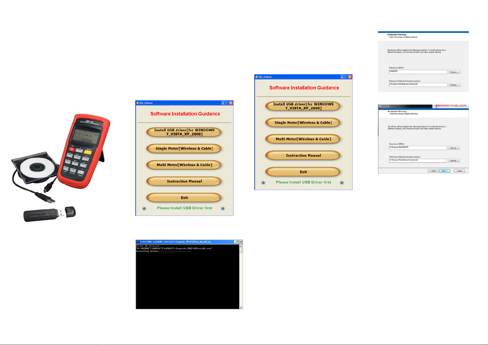
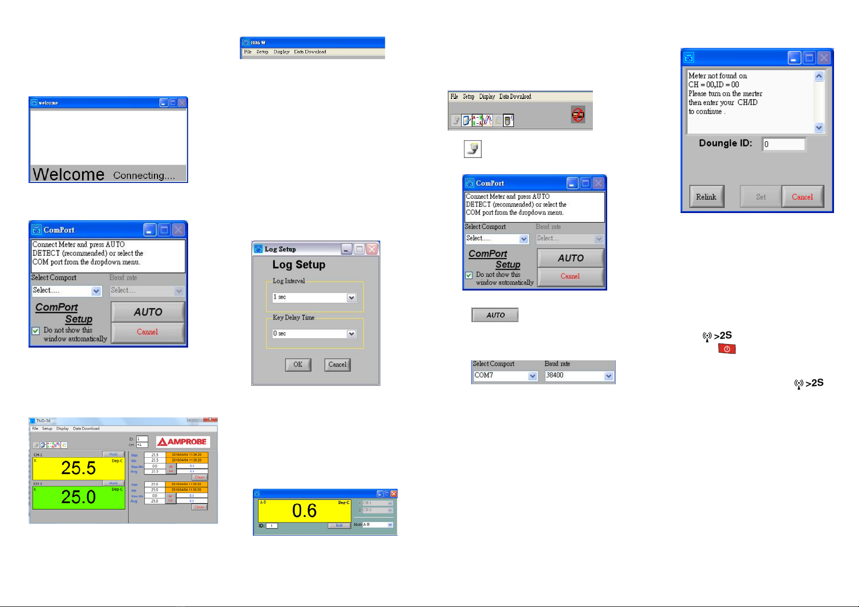
1. Following window comes up automatically after
PC software turn on.
2. For first time use following communication port
setup dialog box. Comes up automatically
3. For communication port setup please refer to
6.1.
4. After finishing communication port setup fol-
lowing Main display window comes up.
Model number shown at up-left corner varies
according to meter.
5. Explanations of comments
5.1 File
About Display manufacturer infor-
mation.
Exit Exit program.
5.2 Setup
Options Environment selection settings
(please refer to 6.2)
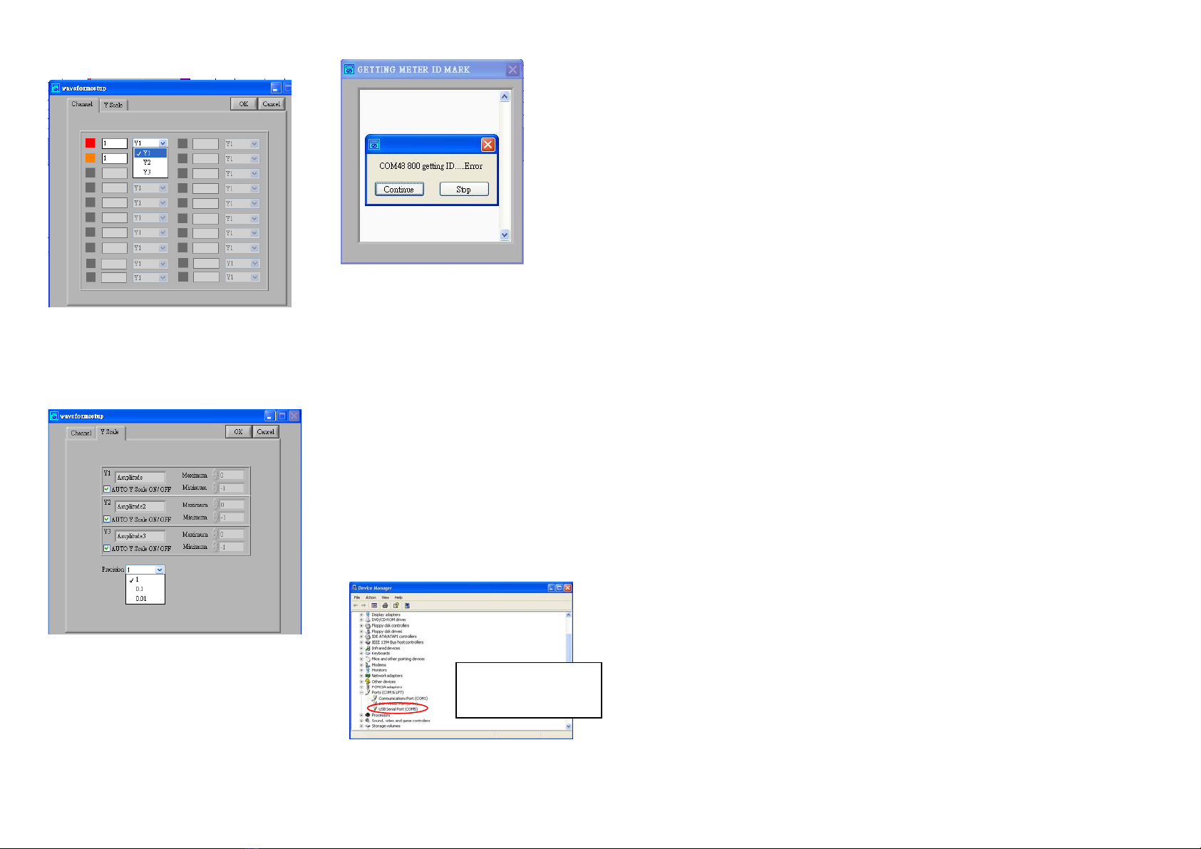
Communication port Check
Search/Settings/Connection
/Showing the current Communi-
cation port used.
Log Setup 1. Log Interval:
Meter Log Interval setup. (De-
fault 1sec)
2. Key Delay Time: Key delay
time setup. (Default 0sec)
User Linear User Linear operation
5.3 Display
Graphic 1. View real time reading and
curves.
2. Window setup refer to 6.4.
Relative Set and display the difference
between two channels.
Received Signal strength indication.
Only available for meters with wireless
function.
5.4 Data Download
Download the saved data from the meter.
(Only for save/data log function mode)
6. Explanations of Toolbar
6.1 Communication port setup dialog
box.
Auto connection
: Click the button let system
select communication port automatically.
Manual connection
Select communication port and baud rate
manually. (Wireless mode, please select
57600 bps, USB mode, please refer to op-
eration manual).
After click on “Do not show this window
automatically” it will not bring up the di-
alog box automatically. It will only func-
tion when you call from the Setup.
For first use, after communication port
setting following dialogue box comes up.
Set meter ID and CH (Only for wireless
models)
1. When message “Meter is found on
CH=00, ID=00” is shown in dialogue
box.
Click “Set” to connect.
2. When message “Meter not found on
CH=00, D=00” is shown in dialogue
box, please reset ID and CH as follow-
ing:
I. Turn off the meter.
II. Press and hold wireless starting key
() and press power “on/off ”
key ( ) for longer than five se-
conds. Display will shown “00”.
III. Turn on wireless function by press-
ing wireless starting key ( ).
IV. Click “Relink”.
V. Repeat 1.
Note
If there are more than one wireless
transceivers operate at same location.
1. Different doungle ID’s should be
given.
2. Distance between 2 doungles must be
more than 30 cm. (12 inches)

6.2 Environment selection settings dia-
log box.
Time setting
Only available for meters with time set-
ting function.
Click “SET” synchronize the clock in me-
ter with the time of PC.
Doungle ID setting
Only available for meters with wireless
function.
Sound of Hi/Lo limit setting
Click data folder icon on the right ,
and select sound effect. (Only use WAVE
format).
Hi/Lo limit setting
1. Setting the Limits.
Audio alarm will be actuated, when
measurements are out of limits.
2. Background color of each channel can
be selected.
Enable or disable the function which stop
data logging when battery is low.
6.3 Relative dialog box.
6.4 Graphic dialog box.
Interval setting
Y scale setting
Select auto mode to accept Y scale auto-
matically set by PC.
Turn off the auto mode to freeze Y scale
at that moment.
Data area
Display last ten measurements.
CH1/CH2 Setting
: Click this button to turn on
or off CH1 and CH2 and select the back-
ground colors.
Start data logger
: Click this button to bring
up “Log Setup” window.
File name: To define the name of the file
in which you want to store the logged
data. The default file name is current
time. (YYYYMMDDHHMMSS).
File type: It can be saved as (*.csv or
*.xls).
User name: The user’s name.
Path: Saved path.
Description: information added by user.
User name and Description will be saved
in the data file.
Click “OK” to start recording.
Stop data logger
: Click to stop data logging
and save the data.
Return to the main window after data
logging ended.
File Exit

6.5 To export data stored in meter to PC.
Only available for meters with save/data
log function.
Click this icon to bring up “Data
download dialog box”.
File menu
File
Exports Data exports
Exit Exit program.
Reload re-load data.
6.6 Received signal strength indication.
Only available for meters with wireless
function.
I. The barograph and number are Received
Signal Strength Indicator (RSSI).
RSSI >= 60 signal is better (in green
range).
60 <= RSSI <=50 signal is good (in
yellow range).
RSSI <= 50 signal is weak. (in red
range)
II. Suggestions for weak signal:
Change the location & orientation of
doungle (vertical to the ground is
best.)
Change location of orientation of me-
ter.
6.7 Low battery warning,, please change
batteries as soon as possible.
7. INTRODUCTION OF MAIN DISPLAY
Left hand side shows reading of each channel
with unit at right-upper corner.
When measure with thermocouple, the type of
thermocouple is shown at left-upper corner.
Right hand side shows maximum (MAX), min-
imum (MIN), range (MAX-MIN) and average
(AVG) value of readings, and times of maximum
and minimum value occur.
Click the button to holds the current reading.
Click the button to reset the reading and time of
MAX, MIN&AVG.
Click the button to activate out of limit alarm.
Hi/Lo limit values are set in 6.
8. USER LINEAR OPERATION
Click this button to create a new blank file
based on the default template.
Click this button to open project.
Click this button to open or find a file.
Click this button to save the active file
with its current fine name, location and
file format.
Click this button to edit data.
Click this button to add data.
Click this button to delete data.
Click this button to calculate this polyno-
mial.
Data complete
Download user linear to meter

Click this button to close this program af-
ter prompting you to save any unsaved
files.
Wireless Features:
Frequency range:
910~920MHz.
868.1~868.5MHz.
Current consumption: Less than 1mA.
Transmission distance: 25M of sight distance
without magnetic interference.
FEDERAL COMMUNICATIONS
COMMISSION
This device complies with Part 15 of the FCC Rules.
Operation is subject to the following two conditions:
(1) this device may not cause harmful interference, and
(2) this device must accept any interference received,
including interference that may cause undesired opera-
tion.
NOTE
This equipment has been tested and found to comply
with the limits for a Class B digital device, pursuant to
Part 15 of the FCC Rules. These limits are designed to
provide reasonable protection. This equipment gener-
ates, uses and can radiated radio frequency energy and,
if not installed and used in accordance with the in-
structions, may cause harmful interference to radio
communications. However, there is no guarantee that
interference will not occur in a particular installation If
this equipment does cause harmful interference to ra-
dio or television reception, which can be determined
by turning the equipment off and on, the user is en-
couraged to try to correct the interference by one or
more of the following measures:
- Reorient or relocate the receiving antenna.
- Increase the separation between the equipment and
receiver.
- Connect the equipment into an outlet on a circuit dif-
ferent from that to which the receiver is connected.
- Consult the dealer or an experienced radio/TV tech-
nician for help.
Shielded interface cables must be used in order to
comply with emission limits.
Changes or modifications not expressly approved by
the party responsible for compliance could void the
user‘s authority to operate the equipment.

Description of Multi-Meter PC
software
Multi Wireless communication
Note: Please insert the Dongle af-
ter SW installation.
Insert Dongle to PC/USB port
System will detect dongle and in-
stall the driver while connecting to
PC USB port.
Wireless Multi-Linking version
instruction:
1. Insert USB dongle to PC’s USB
slot.
2. Start PC software.
PS Software description
1. Enter start page.
2. “New ”: Start with new project
( First use )
2-1 System will search free chan-
nel, please wait.
2-2 Wizard configuration: Please
follow step by step
Note: Please add the wireless in-
strument (ID/CH) one by one to the
system to avoid working channel
collision.
3. “Load “ : Only operate with
saved project.
System will load previous “ ID/CH”
from saved file.
3-1 Please select the saved file
(.ini)
3-2 Please follow wizard configu-
ration.
4. “Modify” :
Load saved project (.ini) and can
also add new meters.
4-1 Please select the saved file
(.ini)
4-2. Please follow wizard configu-
ration
5. Function row.
:Comport Find.
:Start recording data
:Start execution key
:Enlarge display icons.
5-1. Auto Comport Find:
:Comport connection
:Comport connection fail

5-2.
:Start recording channel’s data
and measuring values into txt file.
Default File Save at:
C:\800_Multi\record
The default file name is current
time.
(YYYYMMDDHHMMSS_ID__ File
Member).
5-3 . ”Start key” to activate
connection.
5-3.1 Real time measuring values
display dialogue
Add channels respectively and
display measuring values on the
chart.
5-3.2 Connection status dialogue
Display the connection status of
each meter.
Signal strength RSSI >= 60
means good ( within green area )
Signal strength 60 >= RSSI
>=50 means normal ( within yellow
area )
Signal strength RSSI <= 50
means not good. ( within red ar-
ea )
PS: Suggestions as follows: When
the signal is weak.
6. Magnify display dialogue
For easy and clear to monitor the
channels and data.
7. Dropdown menu
7.1 Clear All : clear List & chart
to empty
7.2 Setup : Set Hi & Lo setting
value to be blinking when they
are over setting values.
7.3 About: Display manufacturer
information.
8. Y axis setting for each channel.
Precision : Y axis resolution setting
AUTO Y Scale ON/ OFF : Select Au-
to-scale
FAQ
Dongle was not found, please
reconnect dongle or check
USB port status as
page2/step2 (CHECK Dongle
CONNECTION PORT)
Working CH occupied, please
exit the software and restart
connecting again.

Description of
Multi Lines PC Software
Insert USB to PC’s USB port
1. Enter start page.
Please insert USB cable with me-
ter, PC software will auto detect
meter device and set ID number
for the meter.
2.“Load “ : Only operate with saved
project.
System will load previous
“ ID/COM” from saved file.
3.“Comport search .
4. . ”Start key” to activate
connection.
Real time measuring values dis-
play.
Add channels respectively and
display measuring values on the
chart.
5. Record data
Start recording channel’s
data and measuring values into txt
file.
6.Save previous “ ID/COM” to ini
file.
7. Magnify display dialogue
For easy and clear to monitor the
channels and data.
8. Dropdown menu
8.1 Clear All : clear List & chart
to empty
8.2 Setup : Set Hi & Lo setting
value to be blinking when they
are over setting values.
8.3 About:Display manufacturer
information.
9. Default File Save at:
C:\800_Multi\record
The default file name is current
time.
(YYYYMMDDHHMMSS_ID__ File Member).

10. Y axis setting for each
channel.
Precision : Y axis resolution setting
AUTO Y Scale ON/ OFF : Select Au-
to-scale
FAQ
Before play must to check
meter power on, if show
message err may be meter
power off or meter has not
connection.
If the ID NO. was not dis-
played while
connecting to USB cable.
Please check COM port sta-
tus as page2. Or if the COM
port is CMO3or COM10,
please change COM port NO.
to others.
PS: The data displayed was list by
connecting sequence, instead
of ID NO. First connecting in-
strument might not be ID 01.
If COM port is COM3,
please change to other
COM port.

Comport Confirmation
Procedure
1. Confirm to see if the port (COM&LPT1) of PC
is assigned to the meter like the following illus-
tration, but it could be other Comport not
COM6.
2. If it is normal, then the change of the port
(COM&LPT1) of PC must follow the following
step to make Comport changes.
Setup1. Click on the Properties of the red frame.
Step2. Choose the Advanced of the red frame as
the illustration blow
Step3. Choose Comport other than COM10,
COM3 and the COM without “IN USE”
like the illustration below.
Step4. Complete the above steps and re-scan the
device. And start opening the software to
do Auto-Connection.
Table of contents
Other Amprobe Measuring Instrument manuals

Amprobe
Amprobe UDM45 User manual

Amprobe
Amprobe SM-20-A User manual

Amprobe
Amprobe ACD-45PQ User manual

Amprobe
Amprobe PM55A User manual

Amprobe
Amprobe SM-10 User manual

Amprobe
Amprobe CR50A User manual

Amprobe
Amprobe THWD-3 User manual

Amprobe
Amprobe DM-5 User manual

Amprobe
Amprobe ACD - 50NAV User manual

Amprobe
Amprobe TH-1 User manual

Amprobe
Amprobe TMA10A User manual

Amprobe
Amprobe AM-270 User manual

Amprobe
Amprobe MAN02-A User manual

Amprobe
Amprobe MAN15 User manual

Amprobe
Amprobe SOLAR-500 User manual

Amprobe
Amprobe TMA5 User manual

Amprobe
Amprobe TMA40-A User manual

Amprobe
Amprobe SM-10 User manual

Amprobe
Amprobe AT-3500 User manual

Amprobe
Amprobe CO2-100 User manual